MSM EN DE NL FR ES SV FI HU CS LT LV TR MK
|
|
|
- Sandra Ström
- för 5 år sedan
- Visningar:
Transkript


1 MSM1039 EN DE NL FR ES SV FI HU CS LT LV TR MK Original instructions 04 Übersetzung der Originalbetriebsanleitung 11 Vertaling van de oorspronkelijke gebruiksaanwijzing 19 Traduction de la notice originale 27 Traducción del manual original 35 Översättning av bruksanvisning i original 43 Alkuperäisten ohjeiden käännös 50 Eredeti használati utasítás fordítása 57 Překlad püvodního návodu k používání 65 Originalios instrukcijos vertimas 73 Instrukciju tulkojums no oriģinālvalodas 80 Orijinal talimatların çevirisi 88 Превод на оригиналните упатства 95


2 Fig Fig


3 Fig Fig. 4 Fig. 5 Fig. 6 3
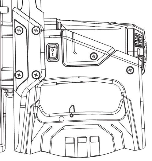
4 EN RADIAL MITRE SAW MSM1039 Weight Lpa (sound pressure) Lwa (acoustic capacity) 12 kg db(a) db(a) Thank you for buying this Ferm product. By doing so you now have an excellent product, delivered by one of Europe s leading suppliers. All products delivered to you by Ferm are manufactured according to the highest standards of performance and safety. As part of our philosophy we also provide an excellent customer service, backed by our comprehensive warranty.we hope you will enjoy using this product for many years to come. The numbers in the following text refer to the pictures on page 2-3 Read the operating instructions carefully before using this device. Familiarise yourself with its functions and basic operation. Service the device as per the instructions to ensure that it always functions properly. The operating instructions and the accompanying documentation must be kept in the vicinity of the device. Intended use The electro tool is intended as a stationary machine for making straight lengthways and crossways cuts in wood. Horizontal mitre angles of -45 to +45 as well as vertical bevel angles of -45 are possible. This saw is intended for sawing wood only. Do not use the saw to cut materials other than wood. 1. MACHINE INFORMATION Technical specifications Mains voltage Capacity Machine class No load speed Saw blade measurement Angle for mitring Angle for bevelling Mitre saw maximum sawing capacity: Mitre 0º, Bevel 0º Mitre 0º, Bevel 45º Mitre 45º, Bevel 0º Mitre 45º, Bevel 45º V~, 50Hz 1500 W II (double insulated) 4.500/min 210x30x2.8mm 45º (left and right) 45º (left only) 70x305mm 35x305mm 70x210mm 35x210mm Vibration level The vibration emission level stated in this instruction manual has been measured in accordance with a standardised test given in EN ; it may be used to compare one tool with another and as a preliminary assessment of exposure to vibration when using the tool for the applications mentioned. - using the tool for different applications, or with different or poorly maintainted accessories, may significantly increase the exposure level - the times when the tool is switched off or when it is running but not actually doing the job, may significantly reduce the exposure level Protect yourself against the effects of vibration by maintaining the tool and its accessories, keeping your hands warm, and organizing your work patterns. Features Figs. 1, 2, 3, 4 and 5 1. On/off switch 2. On/off switch for laser 3. Lock-off button 4. Carbon brush cover 5. Lock-pin 6. Blade protective cover 7. Workpiece clamp 8. Guide fence 9. Knob adjusting saw angle 10. Locking knob 11. Locking paddle 12. Knob over sliding support 13. Connection dust bag 14. Bevel angle 16. Cover 17. Saw blade bolt 18. Flange 19. Screw 20. Screw retraction arm 21. Extension pieces (left and right) 22. Lock-button saw blade 23. Angle indicator 4
5 EN 2. SAFETY INSTRUCTIONS By using electric tools basic safety precautions should always be followed to reduce the risk of fire. Electrical shock and personal injury. Always read the specific product instruction manual and the safety instructions before attempting to operate the power tool and store these instructions. Install of a stationary machine. Fig. 6 This machine is a stationary machine and for safety reasons must always be firmly installed and not used for mobile applications. You can install the machine in two ways: a) As a stationary machine on a workbench. In case the machine must be secured to the workbench with 4 bolts b) As a stationary machine on a sub frame. In this case the machine must be secured to the sub frame with 4 bolts and the sub frame anchored with 4 bolts to the floor plate with dimensions of at least 1 square meter Symbols The following symbols are important for the operations of your power tool. The correct interpretations of the symbols helps you operate the power tool more save Denotes risk of personal injury, loss of life or damage to the tool in case of nonobservance of the instruction in this manual Caution, risk of electric shock Keep bystanders away Wear eye protection Wear ear protectors. Exposure to noise can cause hearing loss. Wear a dust mask Danger Area! Keep hands far away (10cm) from the cutting area while the machine is running. Danger of injury when coming in conatct with the saw blade Do not direct the laser beam at persons or animals and do not stare into the laser beam yourself, not even from a distance. This power tool produced laser class 2 laser radiation according to EN This lead can lead to person being blinded Disc dimensions. Observe the dimensions of the saw blade. The hole diameter must match the tool spindle without play. *Use only a fill ring which is specified by supplier, filling ring may not have any play Tranport the machine only when the machine is in inward transport position 1. Work area safety a) Keep work area clean and well lit. Cluttered or dark areas invite accidents b) Do not operate power tools in explosive atmospheres, such as in the presence of flammable liquids, gases or dust. Power tools create sparks which may ignite the dust or fumes c) Keep children and bystanders far away while operation a power tool. Distractions can cause you to lose control, or material can shut away d) Never leave the machine unattended without first disconnecting it from the mains voltage. 2. Personal safety a) If you are not familiar with using such machine. You would be better to be informed first by a professional, an instructor or by a technician b) Store idle power tools out of the reach of children. Power tools are dangerous in the hands of untrained users c) Keep power tools dry, clean and free from oil and grease. Properly maintained power tools are safer and easier to control. Grease oil handles are slippery causing loss of control d) Make sure you always have a clean and tidy working environment. You could slip or trip e) Stay alert, watch what you are doing and use common sense when operating a power tool 5
6 EN f) Do not overreach. Keep proper footing and balanced at all the time. This enables better control of the power tool in unexpected situations g) Do not work with a machine while you under the influence of alcohol, drugs or medication. Inattention while operating power tools may result in very dangerous injury h) Use always protective equipment. Always wear eye protection, dust mask, hearing protectors and safety shoes. By service on machine or raw materials use gloves. Keep your hair back. Reduce changes on personal injury i) Be careful when sawing double miter joints. Saw blade, Work piece and your hands must be always visible during sawing j) Never saw more than one piece of work at the same time k) Make sure that the piece of work not have any nails/ staples or other foreign objects in it l) Never process metal or stone with this machine m) Do not work with material containing asbestos 3. Power tool safety The first time that the machine is used and then every subsequent time that it is used: Before carrying out any work on the machine, disconnect the mains plug from the power supply. General: Check the entire saw machine. If any part of the machine is missing, bent, damaged or is dysfunctional in any other way, or if any mechanical and/or electrical faults occur or are visible, or if the machine makes any extremely loud noises, refer to the user manual. If any defects are detected on the machine, they must all be rectified before the machine is used. Only original parts should be used! If you have any outstanding concerns which could affect your own safety or the safety of the machine, please consult the machine supplier. Electrical a) Always use an Original power plug which matches the outlet, do not use an adapter plug with earthed (grounded) power tools. Unmodified plugs and matching outlets will reduce risk of electrical shock b) Do not use the machine with a damaged power cable. Do not touch the damaged cable and pull the mains plug when the cable is damaged while working. Damaged cables increase the risk of an electrical shock c) Check the cable regularly and have a damaged cable repaired. Replacing cables or plugs. Immediately throw away old cables or plugs when they have been replaced by new ones. It is dangerous to insert the plug of a loose cable in the wall outlet. Use original power cord and plugs, repairing only through an authorized person, this will ensure that the safety of the power tool is maintained! d) To prevent electrical shocks. When plugging the plug into the socket the metal pins must not be touched in any way whatsoever e) Do not expose power tools to rain or wet conditions. Water entering a power tool will increase the risk of electrical shock f) Never use the cord to pull the plug out of the socket. Keep the cord and plug away from oil, heat and sharp objects g) When operating a power tool outdoors, use an extension cord suitable for outdoor use. Use a cord for outdoor use reduces the risk of electric shock h) When machine is equipped with laser. Do not direct the laser beam at persons or animals and do not stare into the laser beam yourself. Not even in distance. Laser must be according to EN Class 2. i) Repairs of a laser may only be carried out by the laser manufacture or a specialist j) If operating a power tool in a damp location is unavoidable, use a residual current device (RCD) protected supply. Use of an RCD reduces the risk of electric shock Mechanical a) Before you start the machine, check if the saw blade is allowed to rotate freely. Check in every different position of the saw machine if the saw blade revolves freely, if the saw blade touches anything the machine must be adjusted or repaired. b) Do not use the power tool if the switch does not turn on and off. A power tool that cannot be controlled with the switch is dangerous and must be repaired. 6
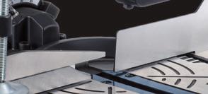
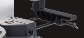
7 EN c) Always use saw blades with the correct size and shape. Use saw blades recommended by the manufacture (EN-847-1). Saw blades that do not match the mounting hardware of the saw will run eccentrically, causing loss of control. d) Never use too small or too big saw blades. This is very dangerous e) Never remove marking on saw blade. Technical information must always visible to make the right choices by exchanging the saw blade f) Secure the work piece. Always clamp work piece with clamping devices, this is much safer than by hand g) Never leave the machine before the complete stopped h) Do not use High speed steel saw blades (HSS). Saw blade can easily break i) Do never use dull, cracked, bent or damaged saw blades. Before use pull the mains plug and check the saw blade. Damaged or unsharpened saw blades produce narrow kerf, excessive friction, blade binding and kickback. Exchange damaged saw blades immediately, always use original flenses, nut and/ or bolts. j) Remove any adjusting key or wrench before turning the power tool. A wrench or a key left attached to a rotating part of the power tool may result in a personal injury and very dangerous situation k) The arrow marked on the saw blade, which indicates the direction of rotation. Must point in the same direction as the arrow marked on the machine, the saw blade teeth must point downwards on the front of the saw l) Do not touch the saw blade after work before it has cooled. The saw blade becomes very hot while working m) Protect the saw blade from strikes and shocks. Do not apply side pressure to the saw blade n) Do not force the power tool. Use the correct power tool for your application. The correct power tool will do the job better and safer at the rate which it was signed o) Never stand on the power tool. Serious injury can occur when the power tool tips over. Always use extra support for more stability of the machine p) Machine is provided with devices for the connection of dust extraction, ensure these are connected and properly used. Dust collection reduce dust- related hazard s q) Maintain the air outlets at the machine. Dust must be removed. r) Make sure that the guard operates properly and that it can move freely. Never lock the guard in place when opened s) Never remove cutting remainders from the sawing area while the machine is running. Always guide the tool arm back to the neutral position first and then switch the machine off t) Guide the saw blade against the work piece only when the machine is switched on. Otherwise there is a risk of a kickback, when the saw blade becomes wedged in the work piece u) If the saw blade should become jammed. Switch the machine off and hold the work piece until the saw blade comes to a complete stop v) To prevent a kick back. The work piece may not be moved until after the machine has complete stopped. Correct the cause for the jamming of the saw blade before restarting the machine w) When sawing profile sections, round pieces or other pieces, always press the piece of work against the stop and can t move, so it cannot till or turn or move while sawing. x) Never use the machine to saw pieces of work that are to small that they cannot be secured safely. Small pieces of wood or other objects that come in contact with the rotating saw blade can strike the operator or out standers with high speed y) When sawing always use the additional supports z) For sawing of large piece work that not supported. Use extra supports aa) Never make warning signs on the machine unrecognizable. Technical information or machine type information must be always visible on machine. At the end of the sawing process, keep the saw head downstairs, switch off the machine and wait until the all moving parts has come to a stop before you take your hands off the machine. 3. ASSEMBLY AND ACCESSORIES Installation of the mitre saw Place one sidebar (21) on the right-hand side of the machine and the other sidebar on the left-hand side of the machine. 7
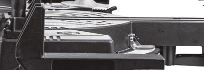
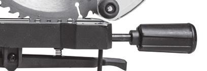
8 EN Place the work piece clamp (7) on the left or right side of the machine. Hold the handgrip and move the saw slightly downwards and then pull the pin (5) out slightly so that saw moves upwards. Note: Never use the mitre saw without the extension pieces supplied. Make sure that they are correctly mounted. Sliding fence Fig.2 For safety reasons, this machine is equipped with a moveable guide fence to used in normal and bevel cutting. For normal straight cross-cuts and mitre cuts, always adjust the sliding fence (8) to the end and fix well to provide safety support for work piece. For bevel cuts, adjust the sliding fence (8) to a suitable position as close as to the saw blade surface but avoid interfere the saw blade movement and ensure to fix well. Changing the saw blades Fig. 4 and 5 Only use saw blades that are sharp and undamaged. You must immediately replace chipped or bent saw blades. DANGER: Do not use any blade larger than the stated capacity of the saw. It may come into contact with the blade guard and cause harm. Do not use a blade too thick to allow the outer blade washer to engage with the flats on the spindle. This will prevent the blade screw from securing the blade on the spindle. Do not use this saw to cut metal or masonry. Disconnect the machine from the power supply. Remove the screw (20) that holds the retraction arm to the blade cover. Remove the screw (19) in order to remove the bolt-cover by lifting the blade cover (6) upwards. Both saw blade bolt (17) and Flange (18) should be visible now like shown in fig. 5. Press the saw blade lock button (22) Rotate the saw blade carefully by hand until the blade locks. Use hex key to remove the saw blade bolt (17) by loosening in a clockwise direction. Remove the Flange (18) and the saw blade Replace the saw blade making sure that the arrow marked on the saw blade must point in the same direction as the arrow shown marked on the machine. The saw blade teeth must point downwards. Fix the saw blade bolt (17) use the saw blade lock button (22) in order to secure tightly Lower the blade cover (6) in order for the boltcover to fall back into place and tighten the screw (19) Attach the retraction arm back onto the blade cover (6) by tightening the screw (20) Rotate the saw blade and check if the guard operates freely Adjusting the cutting angle Fig Adjusting Mitre Angles The mitre angle can be set between 45 left side and 45 right side Loosen the locking knob (10) Press the locking paddle (11) and turn the saw table left or right by the locking knob (10) until the angle indicator (23) indicates the required angle. Release the locking paddle (11) and tighten the locking knob (10) Pre-settings (quick settings) on the following degrees: -45, -30, -22.5, -15, 0, 15, 22.5, 30, 45. Press the locking paddle (11) when turning the baseplate, release the paddle before reaching the requested degrees and the plate with click into the pre-setting itself. Adjusting Bevel Angles Fig. 1 and 3 The bevel angle can be set between 0 and 45. Loosen the adjusting knob (9) Tilt the saw by using the handle until the angle indicator (14) indicates the required angle. Tighten the adjusting knob (9) Changing the carbon brushes Fig. 2 Disconnect the machine from the power supply Unscrew the cover (4). Replace the carbon brushes with the exact type of brushes Tighten the cover (4) again. 8
9 EN Note: Always replace both carbon brushes at the same time, never use a mixture of old and new brushes. Mounting the dust bag Fig. 1 Press in the clamp of the dust bag (13) and slide it onto the opening on the back of the machine. The dust bag stays in place when you release the clamp. 4. OPERATION Using the mitre saw Fig. 1 Before use, always check for faults or defects! Set the desired sawing angle of the machine. Put the plug into the socket. Fix the piece of work in place using the clamp (7): make sure that the material is well clamped in place! Hold the material tightly on the left side while making sure that you keep a safe distance from the blade of the saw. To start the machine, press and hold the Lockoff button (3) and press the on/off switch (1). Make sure that the saw blade has reached full speed before allowing it to touch the piece of work to be sawn. Now bring the saw slowly downwards so that the saw blade saws through the piece of work and passes through the slot in the table. Do not put any pressure on the saw. Give the machine time to saw through the piece of work. Bring the machine gently up again and switch it off by letting go of the switch (1). Using the slide-function Fig. 1 The machine must be firmly bolted to a workbench. Use the slide-function for sawing wide workpieces: Fix the piece of work in place using the clamp Loosen the knob (12) Slide the machine completely towards yourself Turn on the machine using the switch Bring the saw slowly downwards so the saw blade saws through the piece of work Push the machine slowly backwards Bring the machine gently up again and switch it off by letting go of the switch Using the laser Fig. 2 To switch on the laser, press the on/off switch 2. To switch off the laser, release the on/off switch 2. Transport position When moving the saw, make sure the saw is in inward position. Check that all locks and tensioning devices are secure: Make sure the mitre angle is set to 0 Make sure the bevel angle is set to 0 Lock the Knob adjusting saw angle (9) by turning it clockwise Slide the machine completely towards yourself Lock the sliding function by turning Kob over sliding support (12) clockwise Unlock the Lock pin (5) on the right hand side of the machine Push the machine completely downwards Lock the Lock pin (5) on the right hand side of the machine Only lift the machine by the solid underside of the machine. Do not lift the saw by the switch handle. 5. SERVICE AND MAINTENANCE Always make sure that the machine is not connected to the mains electricity when you carry out any maintenance of the mechanism. Slide rails Dirt can damage the slide rails and thereupon the operating of the machine. Clean the slide rails regularly with a soft cloth. Drip some lubricating oil on the slide rails Move the mitre saw forwards and backwards so the oil spreads over the complete rails These machines are designed to function for a long time without any problems with a minimum 9
10 EN of maintenance. By cleaning the machine regularly and using it in the correct way you can contribute to a long life of your machine. Cleaning Clean the machine housing regularly with a soft cloth, preferably after each time you use the machine. Make sure that the ventilation slots are free of dust and dirt. For stubborn dirt use a soft cloth dampened with soapy water. Never use solvents such as benzene, alcohol, ammonia, etc. These types of solvents can damage the plastic parts. Problem solving 1. The motor does not start The plug is not in the socket The power cord is broken The switch is defective. Take the machine to your dealer for repair. 2. The saw cut is not even (jagged) The saw blade must be sharpened The saw blade is mounted back to front The saw blade is clogged with resin or sawdust The saw blade is not suitable for the piece of work being used 3. The height and/or mitre lever is obstructed Chips and/or dust must be removed 4. The motor has difficulty in reaching full speed The extension cord is too thin and/or too long The mains voltage is less than 230 V 5. The machine vibrates excessively The saw blade is damaged 6. The machine becomes excessively hot The ventilation slots are blocked. Clean them out with a dry cloth. 7. The electromotor runs unevenly The carbon brushes are worn out. Replace the carbon brushes or consult your dealer. Lubrication The machine does not need any extra lubrication. Faults Should a fault occur, e.g. after wear of a part, please contact the service address on the warranty card. In the back of this manual you find an exploded view showing the parts that can be ordered. ENVIRONMENT To prevent damage during transport the machine is delivered in sturdy packaging. The packaging is made of recyclable material wherever possible, so make use of the possibility of recycling the packaging. When you replace a machine, take the old one to your local dealer. Here it will be dealt with in an environmentally friendly way. Damaged and/or disposed of electrical or electronic devices must be dropped off at recycling stations intended for that purpose. Only for EC countries Do not dispose of power tools into domestic waste. According to the European Guideline 2012/19/EU for Waste Electrical and Electronic Equipment and its implementation into national right, power tools that are no longer usable must be collected separately and disposed of in an environmentally friendly way. WARRANTY Read the warranty conditions on the separately supplied warranty card. The product and the user manual are subject to change. Specifications can be changed without further notice. 10
11 DE RADIALGEHRUNGSSÄGE MSM1039 Vielen Dank für den Kauf dieses Ferm Produkts. Hiermit haben Sie ein ausgezeichnetes Produkt erworben, dass von einem der führenden Lieferanten Europas geliefert wird. Alle von Ferm an Sie gelieferten Produkte sind nach den höchsten Standards von Leistung und Sicherheit gefertigt. Teil unserer Firmenphilosophie ist es auch, Ihnen einen ausgezeichneten Kundendienst anbieten zu können, der von unserer umfassenden Garantie unterstützt wird. Wir hoffen, dass Sie viele Jahre Freude an diesem Produkt haben. Die Zahlen im nachstehenden Text entsprechen den Abbildungen auf Seite 2-3 Lesen Sie diese Bedienungsanleitung aufmerksam, bevor Sie die Maschine in Betrieb nehmen. Machen Sie sich mit der Funktionsweise und der Bedienung vertraut. Warten Sie die Maschine entsprechend der Anweisungen, damit sie immer einwandfrei funktioniert. Die Betriebsanleitung und die dazugehörige Dokumentation müssen in der Nähe der Maschine aufbewahrt werden. Vorgesehene verwendung Dieses Elektrowerkzeug ist als feststehende Maschine zum Sägen von Längs- und Querschnitten in Hölzern vorgesehen. Horizontale Gehrungswinkel von -45 bis +45 sowie vertikale Neigungswinkel von -45 sind möglich. Diese Säge ist nur zum Sägen von Holz bestimmt. Verwenden Sie die Säge nicht, um andere Materialien als Holz zu schneiden. 1. GERÄTEDATEN Technische daten Spannung Leistung Geräteklasse Leerlaufdrehzahl Sägeblattabmessungen V, 50Hz 1500 W II (Doppelisolierung) 4.500/min 210x30x2.8 mm Winkel für Gehrungsschnitt 45 (links und rechts) Winkel für Schrägschnitt 45 (nur links) Max. Sägekapazität der paneelsäge Gehrungsschnitt 0, Schrägschnitt 0 70x305 mm Gehrungsschnitt 0, Schrägschnitt 45 35x305 mm Gehrungsschnitt 45, Schrägschnitt 0 70x210 mm Gehrungsschnitt 45, Schrägschnitt 45 35x210 mm Gewicht 12 kg Lpa (Schalldruck) db(a) Lwa (Schallleistung) db(a) Vibrationsstufe Die im dieser Bedienungsanleitung angegebene Vibrationsemissionsstufe wurde mit einem standardisierten Test gemäß EN gemessen; Sie kann verwendet werden, um ein Werkzeug mit einem anderen zu vergleichen und als vorläufige Beurteilung der Vibrationsexposition bei Verwendung des Werkzeugs für die angegebenen Anwendungszwecke. die Verwendung des Werkzeugs für andere Anwendungen oder mit anderem oder schlecht gewartetem Zubehör kann die Expositionsstufe erheblich erhöhen Zeiten, zu denen das Werkzeug ausgeschaltet ist, oder wenn es läuft aber eigentlich nicht eingesetzt wird, können die Expositionsstufe erheblich verringern Schützen Sie sich vor den Auswirkungen der Vibration durch Wartung des Werkzeugs und des Zubehörs, halten Sie Ihre Hände warm und organisieren Sie Ihren Arbeitsablauf. Funktionen Abb. 1, 2, 3, 4 und 5 1. Ein-/Aus-Schalter 2. Ein-/Aus-Schalter für Laser 3. Einschaltsperre 4. Kohlebürstenabdeckung 5. Sicherungsstift 6. Klingenschutzabdeckung 7. Werkstückklemme 8. Führungsgitter 9. Justierknopf für den Sägewinkel 10. Arretierungsknopf 11. Verriegelungsschaufel 12. Knopf über der gleitenden Stütze 13. Anschluss Staubbeutel 14. Keilwinkel 16. Abdeckung 11
12 DE 17. Sägeblattschraube 18. Flansch 19. Schraube 20. Schraubenrückzugsarm 21. Erweiterungsstücke(links und rechts) 22. Verriegelungsknopf Sägeblatt 23. Winkelmesser 2. SICHERHEITSANWEISUNGEN Bei der Nutzung von Elektrowerkzeugen sollten die grundlegenden Sicherheitshinweise immer eingehalten werden, um die Brandgefahr zu reduzieren. Stromschlag und Personenschaden. Lesen Sie immer die spezifische Produktbetriebsanleitung und die Sicherheitsanweisungen, bevor Sie versuchen, das Elektrowerkzeug zu bedienen und speichern Sie diese Anweisungen. Installation einer stationären Maschine. Abb. 6 Bei dieser Maschine handelt es sich um eine stationäre Maschine und aus Sicherheitsgründen muss diese immer fest installiert und darf nicht für mobile Anwendungen verwendet werden. Sie können die Maschine auf zwei Arten installieren: a) Als stationäre Maschine auf einer Werkbank. In dem Fall muss die Maschine mit vier Schrauben an der Werkbank befestigt werden b) Als stationäre Maschine auf einem Fahrschemel. In diesem Fall muss die Maschine mit 4 Schrauben auf dem Hilfsrahmen gesichert werden und der Hilfsrahmen mit 4 Schrauben auf der Bodenplatte mit einem Maß von mindestens einem Quadratmeter verankert werden Symbole Die folgenden Symbole sind wichtig für den Betrieb Ihres Elektrowerkzeugs. Die korrekten Auslegungen der Symbole hilft Ihnen dabei, das Elektrowerkzeug sicherer zu bedienen Bezeichnet das Risiko von Personenschaden, Verlust des Lebens oder von Schaden am Werkzeug im Falle der Nichteinhaltung der Anweisungen in diesem Handbuch Vorsicht, Stromschlaggefahr Halten Sie Zuschauer fern Augenschutz tragen Ohrenschützer tragen. Lärmexposition kann zum Hörverlust führen. Tragen Sie eine Staubschutzmaske Gefahrenbereich! Halten Sie die Hände (10 cm) vom Schnittbereich entfernt während die Maschine in Betrieb ist. Verletzungsgefahr, wenn man in Kontakt mit dem Sägeblatt gerät Richten Sie den Laserstrahl nicht auf Personen oder Tiere und starren Sie nicht in den Laserstrahl, auch nicht aus der Distanz. Dieses Elektrowerkzeug erzeugt einen Laser mit einer Laserstrahlung der Klasse 2 gemäß EN Diese kann dazu führen, dass Personen erblinden Scheibenabmessungen Beachten Sie die Abmessungen des Sägeblatts. Der Gesamtdurchmesser muss der Werkzeugspindel ohne Spiel entsprechen. *Verwenden Sie nur einen Füllring, der vom Anbieter angegeben wird, der Füllring darf kein Spiel haben Transportieren Sie die Maschine nur, wenn sie in der Eingangstransport position ist 1. Sicherheit im Arbeitsbereich a) Halten Sie den Arbeitsbereich sauber und sorgen Sie dafür, dass er gut beleuchtet ist. Überladene oder dunkle Bereiche begünstigen Unfälle b) Benutzen Sie Elektrowerkzeuge nicht in explosionsgefährdeten Bereichen, wie z.b. in der Gegenwart brennbarer Flüssigkeiten, Gase oder Staub. Elektrowerkzeuge erzeugen Funken, die den Staub oder die Dämpfe entzünden können c) Halten Sie Kinder und Zuschauer während des Betriebs eines Elektrowerkzeugs in weitem Abstand. Ablenkungen können zum Kontrollverlust führen oder Material kann weggeschoben werden 12
13 DE d) Lassen Sie die Maschine niemals unbeaufsichtigt, ohne sie zunächst von der Netzspannung abzuklemmen 2. Personensicherheit a) Wenn Sie im Umgang mit diesen Maschinen nicht vertraut sind. Am besten lassen Sie sich im Vorfeld von einem Fachmann, einem Ausbilder oder einem Techniker informieren b) Bewahren Sie ungenutzte Elektrowerkzeuge außerhalb der Reichweite von Kindern auf. Elektrowerkzeuge sind in den Händen ungeschulter Nutzer gefährlich c) Halten Sie Elektrowerkzeuge trocken, sauber und frei von Öl und Fett. Ordnungsgemäß gepflegte Elektrowerkzeuge sind sicherer und einfacher zu kontrollieren. Fettige oder ölige Griffe sind rutschig und können zum Kontrollverlust führen d) Stellen Sie sicher, immer ein sauberes und ordentliches Arbeitsumfeld zu haben. Sie könnten ausrutschen oder stolpern e) Bleiben Sie aufmerksam, achten Sie darauf, was Sie tun und wenden Sie beim Betrieb eines Elektrowerkzeugs Ihren gesunden Menschenverstand an f) Übernehmen Sie sich nicht. Sorgen Sie zu jeder Zeit für den richtigen Halt und für Ausgeglichenheit. Dies ermöglicht eine bessere Kontrolle über das Elektrowerkzeug in unerwarteten Situationen g) Arbeiten Sie nicht mit der Maschine, wenn Sie unter Alkohol-, Drogen- oder Medikamenteneinfluss stehen. Unachtsamkeit beim Betrieb von Elektrowerkzeugen kann in sehr gefährlichen Verletzungen resultieren h) Tragen Sie immer eine persönliche Schutzausrüstung. Tragen Sie immer Augenschutz, Staubschutzmaske, Ohrenschutz, Sicherheitsschuhe und lediglich bei Wartungsarbeiten an der Maschine oder bei der Verwendung von Rohstoffen Handschuhe. Binden Sie Ihr Haar zusammen. Reduzieren Sie Personenschäden i) Seien Sie vorsichtig beim Sägen von Doppelgehrungsverbindungen. Das Sägeblatt, das Werkstück und Ihre Hände müssen während des Sägens immer sichtbar sein j) Sägen Sie niemals mehr als ein Werkstück gleichzeitig k) Stellen Sie sicher, dass das Werkstück frei von Nägeln oder sonstigen Fremdkörpern ist l) Verarbeiten Sie niemals Metall oder Stein mit dieser Maschine m) Arbeiten Sie nicht mit asbesthaltigem Material 3. Sicherheit des Elektrowerkzeugs Beim ersten Mal, wenn die Maschine verwendet wird und das jedes weitere Mal, wenn die Maschine genutzt wird: Vor der Durchführung von Arbeiten an der Maschine den Netzstecker von der Stromversorgung trennen. Allgemein: Prüfen Sie die gesamte Sägemaschine. Falls ein Teil der Maschine fehlt, verbogen, beschädigt oder auf andere Art dysfunktional ist, oder wenn sonstige mechanische und/oder elektrische Fehler auftreten oder sichtbar werden oder wenn die Maschine extrem laute Geräusche macht, dann ziehen Sie das Benutzerhandbuch zu Rate. Falls Fehler an der Maschine erkannt werden, müssen diese alle vor Nutzung der Maschine behoben werden. Es dürfen nur Originalteile verwendet werden! Falls Sie noch ausstehende Bedenken haben, die Ihre eigene Sicherheit oder die Sicherheit der Maschine gefährden könnten, nehmen Sie bitte mit dem Maschinenanbieter auf. Elektrisch a) Verwenden Sie immer einen Original- Stromstecker, der zur Steckdose passt, verwenden Sie bei geerdeten Elektrowerkzeugen keinen Adapter-Stecker. Nicht modifizierte Stecker und passende Steckdosen reduzieren das Stromschlagrisiko b) Verwenden Sie die Maschine nicht mit einem beschädigten Stromkabel. Berühren Sie das beschädigte Kabel nicht und ziehen Sie den Netzstecker, wenn das Kabel während der Arbeit beschädigt ist. Beschädigte Kabel erhöhen das Stromschlagrisiko c) Prüfen Sie das Kabel regelmäßig und lassen Sie beschädigte Kabel reparieren. Austausch von Kabeln oder Steckern Werfen Sie alte Kabel oder Stecker sofort weg, wenn diese durch neue ersetzt wurden. Es ist gefährlich, den Stecker eines losen Kabels in die Steckdose zu stecken. 13
14 DE Verwenden Sie das Originalstromkabel und die Originalstecker, Reparaturen dürfen nur von einer autorisierten Person durchgeführt werden, so wird sichergestellt, dass die Sicherheit des Elektrowerkzeugs gewahrt bleibt! d) Zur Vermeidung von Stromschlägen. Beim Stecken des Steckers in die Steckdose, dürfen die Metallstifte keinesfalls berührt werden e) Setzen Sie Elektrowerkzeuge nicht dem Regen oder nassen Bedingungen aus. Wenn Wasser in ein Elektrowerkzeug eindringt, erhöht dies das Stromschlagrisiko f) Verwenden Sie niemals das Kabel, um den Stecke aus der Steckdose zu ziehen. Halten Sie Kabel und Stecker von Öl, Wärme, und spitzen Gegenständen entfernt g) Verwenden Sie bei der Nutzung eines Elektrowerkzeugs im Außenbereich ein dafür geeignetes Verlängerungskabel. Die Nutzung eines Kabels für den Außenbereich reduziert das Stromschlagrisiko h) Wenn die Maschine mit Laser ausgestattet ist. Richten Sie den Laserstrahl nicht auf Personen oder Tiere und starren Sie nicht in den Laserstrahl. Auch nicht aus der Ferne. Der Laser muss der EN , Klasse 2 entsprechen. i) Laserreparaturen dürfen nur vom Laserhersteller oder von einem Fachmann durchgeführt werden j) Verwenden Sie eine Fehlerstromschutzvorrichtung, wenn der Betrieb eines Elektrowerkzeugs an einem feuchten Ort unvermeidbar ist. Die Nutzung einer Fehlerstromschutzvorrichtung reduziert das Stromschlagrisiko Mechanisch a) Lassen Sie die Maschine frei drehen, bis sie die Maschinenanzahl erreicht, bevor Sie die Maschine starten. Prüfen Sie die verschiedenen Positionen der Sägemaschine, wenn das Sägeblatt frei dreht, wenn das Sägeblatt etwas berührt, muss die Maschine justiert oder repariert werden b) Verwenden Sie das Stromwerkzeug nicht, wenn es sich nicht mit dem Schalter ein- und ausschalten lässt. Ein Stromwerkzeug, dass nicht mit dem Schalter kontrolliert werden kann, muss repariert werden c) Verwenden Sie Sägeblätter immer in der richtigen Größe und Form. Nutzen Sie die vom Hersteller empfohlenen Sägeblätter (EN-847-1) Sägeblätter, die nicht den Befestigungsteilen der Säge entsprechen, zerstören außemittig und verursachen Kontrollverlust. d) Verwenden Sie niemals zu kleine oder zu große Sägeblätter. Das ist sehr gefährlich e) Entfernen Sie niemals die Markierung auf einem Sägeblatt. Technische Informationen müssen immer sichtbar sein, um beim Austausch der Sägeblätter die richtigen Entscheidungen zu treffen f) Sichern Sie das Werkstück. Klemmen Sie das Werkstück immer mit Klemmvorrichtungen fest, das ist viel sicherer als mit der Hand g) Lassen Sie die Maschine niemals allein, bevor Sie vollständig zum Stillstand gekommen ist h) Verwenden Sie keine Sägeblätter aus Schnellarbeitsstahl. Verursacht, dass das Sägeblatt schnell bricht i) Verwenden Sie keine stumpfen, abgebrochenen, verbogenen oder beschädigten Sägeblätter. Ziehen Sie vor dem Gebrauch den Netzstecker und prüfen Sie das Sägeblatt. Verursacht, dass beschädigte oder stumpfe Sägeblätter schmale Kerben, übermäßige Reibung, Sägeblattbindung und Rückschläge erzeugen. Tauschen Sie beschädigte Sägeblätter sofort aus, verwenden Sie immer Original-Flansche, Muttern und Schrauben j) Entfernen Sie alle Einstellschlüssel oder Schraubenschlüssel, bevor Sie das Elektrowerkzeug drehen. Ein Schraubenschlüssel oder ein neben einem rotierenden Teil des Elektrowerkzeugs liegen gelassener Schlüssel kann zu Personenschäden und zu einer sehr gefährlichen Situation führen k) Der auf dem Sägeblatt eingezeichnete Pfeil weist auf die Drehrichtung hin. Muss in die gleiche Richtung zeigen wie der auf der Maschine gekennzeichnete Pfeil, die Sägeblattzähne müssen vorne an der Säge nach unten zeigen l) Berühren Sie das Sägeblatt nach der Arbeit nicht, bis es abgekühlt ist. Das Sägeblatt wird während der Arbeit sehr heiß m) Schützen Sie das Sägeblatt vor Schlägen und Stößen. Wenden Sie keinen Seitendruck auf das Sägeblatt an n) Üben Sie keine Kraft auf das Elektrowerkzeug aus. Verwenden Sie das für Ihre Anwendung richtige Elektrowerkzeug. Das korrekte Elektrowerkzeug wird den Job besser und sicherer zu dem Preis, zu dem es erworben wurde 14
15 DE o) Stellen Sie sich niemals auf das Elektrowerkzeug. Das Umkippen des Elektrowerkzeugs kann ernsthafte Verletzungen verursachen. Verwenden Sie immer eine zusätzliche Stütze, um der Maschine mehr Stabilität zu bieten p) Die Maschine ist mit Vorrichtungen für den Anschluss eines Entstaubungssystems ausgestattet, stellen Sie sicher, dass dieses angeschlossen und ordnungsgemäß verwendet wird. Staubabsaugung reduziert staubbezogene Gefahren q) Warten Sie die Lufteinlässe an der Maschine. Staubansammlungen müssen entfernt werden. r) Stellen Sie sicher, dass der Schutz ordnungsgemäß funktioniert und dass er sich frei bewegen kann. Den Schutz niemals verriegeln, wenn er geöffnet ist s) Schnittreste niemals aus dem Sägebereich entfernen, während die Maschine in Betrieb ist. Den Werkzeugarm immer zuerst in die neutrale Position zurückführen und dann die Maschine ausschalten t) Führen Sie das Sägeblatt nur gegen das Werkstück, wenn die Maschine eingeschaltet ist. Ansonsten besteht ein Rückschlagrisiko, wenn das Sägeblatt im Werkstück eingekeilt wird u) Falls das Sägeblatt eingeklemmt wird. Schalten Sie die Maschine aus und halten Sie das Werkstück fest, bis das Sägeblatt komplett zum Stillstand gekommen ist v) Um einen Rückschlag zu vermeiden. Das Werkstück darf nicht bewegt werden, bis die Maschine komplett zum Stillstand gekommen ist. Korrigieren Sie die Ursache für das Einklemmen des Sägeblatts, bevor Sie die Maschine neustarten w) Beim Sägen von Profilabschnitten, runden Stücken oder sonstigen Stücken das Werkstück immer gegen den Stopp pressen, so dass es sich nicht bewegen kann, damit es sich während des Sägens nicht drehen oder bewegen kann. x) Verwenden Sie die Maschine niemals, um Werkstücke zu sägen, die so klein sind sind, dass Sie nicht gesichert werden können. Kleine Holzstücke oder sonstige Gegenstände, die in Kontakt mit dem rotierenden Sägeblatt kommen, können den Bediener oder Zuschauer bei hoher Geschwindigkeit treffen y) Zum Sägen aller Arbeiten immer zusätzliche Stützen vewenden z) Zum Sägen eines nicht gestützten, großen Werkstücks. Zusätzliche Stützen verwenden aa) Machen Sie Warnschilder auf der Maschine niemals unkenntlich. Technische Informationen oder Informationen zum Maschinentyp müssen auf der Maschine sichtbar sein. Am Ende des Sägeprozesses den Sägekopf nach unten halten, die Maschine ausschalten und warten, bis alle beweglichen Teile zum Stillstand gekommen sind, bevor Sie die Maschine loslassen 3. ZUSAMMENBAU UND ZUBEHÖR Installation der Gehrungssäge Stellen Sie eine Seitenleiste (21) rechts neben die Maschine und die andere Seitenleiste links neben die Maschine. Platzieren Sie die Werkstückklemme (7) links oder rechts neben die Maschine. Halten Sie den Handgriff fest, bewegen Sie die Säge leicht nach unten und ziehen Sie den Stift (5) leicht heraus, so dass sich die Säge nach oben bewegt. Hinweis: Verwenden Sie die Gehrungssäge niemals ohne die im Lieferumfang enthaltenen Erweiterungsstücke. Stellen Sie sicher, dass diese korrekt montiert sind. Schiebegitter Abb.2 Aus Sicherheitsgründen ist diese Maschine mit einem beweglichen Führungsgitter zum Gebrauch beim normalen und Schrägschneiden ausgestattet. Bei normalen geraden Querschnitten und Gehrungsschnitten das Führungsgitter (8) immer mit dem Ende justieren und gut fixieren, um dem Werkstück eine sichere Stütze zu geben. Bei Gehrungsschnitten das Schiebegitter (8) in eine geeignete Position in der Nähe der Sägeblattoberfläche justieren, aber eine Interferenz der Sägeblattbewegung muss vermieden werden und es ist auf eine sichere Fixierung zu achten. 15
16 DE Austausch der Sägeblätter Abb. 4 und 5 Verwenden Sie nur Sägeblätter, die scharf und nicht beschädigt sind. Sie müssen abgebrochene oder verbogene Sägeblätter sofort austauschen. GEFAHR: Verwenden Sie kein Sägeblatt, dass größer als die angegebene Leistung der Säge ist. Es könnte mit dem Blattschutz kommen und Schäden verursachen. Verwenden Sie kein Sägeblatt, dass zu dick ist und verhindert, dass die Sägeblattscheibe in die Flächen auf der Spindel greifen kann. Dies verhindert, dass die Sägeblattschraube das Sägeblatt auf der Spindel sichert. Verwenden Sie die Säge nicht zum Schneiden von Metall oder Mauerwerk Trennen Sie die Maschine von der Stromversorgung. Entfernen Sie die Schraube (20), die den Rückzugsarm an der Sägeblattabdeckung hält. Entfernen Sie die Schraube (19), um die Schraubenabdeckung durch Anheben der Sägeblattabdeckung (6) zu abzunehmen. Sowohl Sägeblattschraube (17) als auch Flansch (18) sollten nun sichtbar sein, wie in Abb. 5 dargestellt. Drücken Sie den Sägeblattsperrknopf (22) Drehen Sie das Sägeblatt vorsichtig mit der Hand, bis das Sägeblatt einrastet. Verwenden Sie den Innensechskant- Schraubendreher, um die Sägeblattschraube (17) durch Lösen im Uhrzeigersinn zu entfernen. Entfernen Sie den Flansch (18) und das Sägeblatt Ersetzen Sie das Sägeblatt und stellen Sie sicher, dass der auf dem Sägeblatt markierte Pfeil in die gleiche Richtung zeigt wie der auf der Maschine gekennzeichnete Pfeil. Die Sägeblattzähne müssen nach unten zeigen. Fixieren Sie die Sägeblattschraube (17) fest, verwenden Sie den Sägeblatt-Sperrknopf (22), um sie festzuziehen Senken Sie die Sägeblattabdeckung (6), damit die Schraubenabdeckung wieder auf ihren Platz zurück kann und ziehen Sie die Schraube (19) fest Befestigen Sie den Rückzugsarm wieder auf der Sägeblattabdeckung (6), indem Sie die Schraube (20) festziehen Drehen Sie das Sägeblatt und prüfen Sie, ob der Schutz sich frei bewegen kann Justierung des Schnittwinkels Abb. 1 und 2 Justierung der Gehrungswinkel Der Gehrungswinkel kann zwischen 45 links und 45 rechts eingestellt werden Lösen Sie den Arretierungsknopf (10) Drücken Sie die Verriegelungsschaufel (11) und drehen Sie den Sägetisch mit dem Verriegelungsknopf (10) nach links oder rechts, bis der Winkelmesser (23) den erforderlichen Winkel anzeigt. Lösen Sie die Verriegelungsschaufel (11) und ziehen Sie den Verriegelungsknopf (10) fest Voreinstellungen (Schnelleinstellungen) bei den folgenden Graden: -45, -30, -22.5, -15, 0, 15, 22.5, 30, 45. Drücken Sie die Verriegelungsschaufel (11) beim Drehen der Grundplatte, lösen Sie die Schaufel, bevor die erforderlichen Grade erreicht werden und die Platte wird eigenständig mit einem Klick in die Voreinstellung einrasten. Justierung des Keilwinkels Abb. 1 und 3 Der Keilwinkel kann zwischen 0 und 45 eingestellt werden. Lösen Sie den Einstellknopf (9) Kippen Sie die Säge mit dem Griff, bis der Winkel messer (14) den erforderlichen Winkel anzeigt. Ziehen Sie den Einstellknopf (9) fest Austausch der Kohlebürsten Abb. 2 Trennen Sie die Maschine von der Stromversorgung Schrauben Sie die Abdeckung (4) ab. Ersetzen Sie die Kohlebürsten mit dem exakt gleichen Bürstentyp Ziehen Sie die Abdeckung (4) wieder fest. Hinweis: Ersetzen Sie immer beide Kohlebürsten gleichzeitig, verwenden Sie niemals eine Mischung aus alten und neuen Bürsten. 16
17 DE Befestigung des Staubbeutels Abb. 1 Drücken Sie die Klemme des Staubbeutels (13) ein und schieben Sie sie auf die Öffnung an der Rückseite der Maschine. Die Staubbeutel bleiben beim Lösen der Klemme an ihrem Platz. 4. BEDIENUNG Benutzung der gehrungssäge Abb. 1 Überprüfen Sie das Gerät vor dem Gebrauch immer auf Mängel oder Fehler! Stellen Sie den gewünschten Sägewinkel des Geräts ein. Stecken Sie den Stecker in die Steckdose: Fixieren Sie das Werkstück mit Hilfe der Klammern (7): Vergewissern Sie sich dabei, dass das Material richtig an seinem Platz aufgespannt ist! Halten Sie das Material an der linken Seite gut fest und vergewissern Sie sich gleichzeitig, dass zwischen Ihnen und dem Sägeblatt ein ausreichender Abstand vorhanden ist. Um die Maschine einzuschalten, halten Sie die Einschaltsperre (3) gedrückt und drücken Sie gleichzeitig auf den Ein-/Aus-Schalter (1). Vergewissern Sie sich, dass das Sägeblatt seine volle Drehzahl erreicht hat, bevor es das zu sägende Werkstück berühren kann. Bewegen Sie die Säge jetzt langsam nach unten, sodass das Sägeblatt das Werkstück durchsägt und sich durch den Schlitz im Tisch bewegt. Üben Sie auf die Säge keinerlei Druck aus. Geben Sie dem Gerät Zeit, das Werkstück durchzusägen. Bewegen Sie das Gerät wieder vorsichtig nach oben und schalten Sie es durch Loslassen des Schalters (1) aus. Nutzung der Gleitfunktion Abb. 1 Die Maschine muss fest mit einer Werkbank verschraubt sein. Verwenden Sie die Gleitfunktion, um breite Werkstücke zu sägen: Fixieren Sie das Werkstück mit der Klemme Lösen Sie den Knopf (12) Schieben Sie die Maschine komplett in Ihre Richtung Schalten Sie die Maschine mit dem Schalter ein Senken Sie die Säge langsam, so dass die Säge durch das Werkstück sägt Schieben Sie die Maschine langsam zurück Ziehen Sie die Maschine wieder leicht nach oben und schalten Sie sie mit dem Schalter aus Verwendung des Lasers Abb. 2 Um den Laser einzuschalten, drücken Sie auf den Ein-/Aus-Schalter 2. Um den Laser auszuschalten, lassen Sie den Ein-/Aus-Schalter 2 los. Transportposition Wenn Sie die Säge bewegen, achten Sie darauf, dass sie eingeklappt ist. Überprüfen Sie, ob alle Sperr- und Spannvorrichtungen gesichert sind: Vergewissern Sie sich, dass der Gehrungswinkel auf 0 eingestellt ist Vergewissern Sie sich, dass der Neigungswinkel auf 0 eingestellt ist Sichern Sie den Knopf zur Einstellung des Säge winkels (9), indem Sie ihn im Uhrzeigersinn drehen Schieben Sie die Maschine vollständig in Ihre Richtung Verriegeln Sie die Gleitfunktion, indem Sie den Knopf über die Gleithalterung (12) im Uhrzeigersinn drehen Entriegeln Sie den Verriegelungsstift (5) auf der rechten Seite der Maschine Schieben Sie die Maschine vollständig nach unten Verriegeln Sie den Verriegelungsstift (5) auf der rechten Seite der Maschine Heben Sie die Maschine nur an der festen Unterseite der Maschine an. Heben Sie die Säge nicht am Schaltergriff an. 17
18 DE 5. SERVICE UND WARTUNG Vergewissern Sie sich immer, dass das Gerät nicht an das Netz angeschlossen ist, wenn Sie Wartungsarbeiten an dem Mechanismus vornehmen. Gleitschienen Schmutz kann die Gleitschienen und somit die Funktion der Säge beschädigen. Reinigen Sie die Gleitschienen regelmäßig mit einem weichen Tuch. Geben Sie etwas Schmieröl auf die Gleitschienen. Bewegen Sie die Gehrungssäge vorwärts und rückwärts, sodass sich das Öl komplett über die Schienen verteilen kann. Geräte sind dafür ausgelegt, über einen langen Zeitraum problemlos und mit minimaler Wartung zu arbeiten. Durch regelmäßiges Reinigen des Geräts und richtige Benutzung können Sie zu einer langen Lebensdauer des Geräts beitragen. Reinigung Reinigen Sie das Gerätegehäuse regelmäßig mit einem weichen Tuch, vorzugsweise nach jeder Benutzung. Vergewissern Sie sich, dass die Belüftungsschlitze frei von Staub und Schmutz sind. Entfernen Sie hartnäckigen Schmutz mit einem weichen, mit Seifenwasser angefeuchteten Tuch. Verwenden Sie niemals Lösungsmittel wie Benzol, Alkohol, Ammoniak usw., da diese Lösungsmittel die Kunststoffteile beschädigen können. Problemlösung 1. Der Motor läuft nicht an Der Stecker ist nicht in der Steckdose. Das Netzkabel ist unterbrochen. Der Schalter ist defekt. Bringen Sie das Gerät zwecks Reparatur zu Ihrem Vertragshändler. 2. Der Sägeschnitt ist nicht gleichmäßig (ist eingekerbt) Das Sägeblatt muss geschärft werden. Das Sägeblatt ist mit der Rückseite nach vorn eingebaut. Das Sägeblatt ist durch Harz oder Sägespäne verstopft. Das Sägeblatt ist für das betreffende Werkstück nicht geeignet. 3. Der Höhen- und/oder Gehrungsschnitthebel ist verstopft Späne und/oder Staub müssen entfernt werden. 4. Der Motor erreicht die volle Drehzahl nur schwer Das Verlängerungskabel ist zu dünn und/oder zu lang Die Netzspannung beträgt weniger als 230 Volt. 5. Das Gerät vibriert übermäßig Das Sägeblatt ist beschädigt. 6. Das Gerät wird zu heiß Die Belüftungsschlitze sind blockiert. Schlitze mit einem trockenen Tuch reinigen. 7. Der Elektromotor läuft ungleichmäßig Die Kohlebürsten sind abgenutzt. Erneuern Sie die Kohlebürsten oder fragen Sie Ihren Vertragshändler. Schmieren Die Maschine braucht keine zusätzliche Schmierung. Störungen Sollte beispielsweise nach Abnutzung eines Teils ein Fehler auftreten, dann setzen Sie sich bitte mit der auf der Garantiekarte angegebenen Serviceadresse in Verbindung. Im hinteren Teil dieser Anleitung befindet sich eine ausführliche Übersicht über die Teile, die bestellt werden können. UMWELT Um Transportschäden zu verhindern, wird die Maschine in einer soliden Verpackung geliefert. Die Verpackung besteht weitgehend aus verwertbarem Material. Benutzen Sie also die Möglichkeit zum Recyceln der Verpackung. Schadhafte und/oder entsorgte elektrische oder elektronische Geräte müssen an den dafür vorgesehenen Recycling-Stellen abgegeben werden. 18
SAFETY PRECAUTIONS SPECIFICATIONS
 SAFETY PRECAUTIONS Read the instructions carefully before use and save them for future reference. Before you connect the appliance: Ensure that the voltage rating on the type plate corresponds to your
SAFETY PRECAUTIONS SPECIFICATIONS
 SAFETY PRECAUTIONS Read the instructions carefully before use and save them for future reference. Before you connect the appliance: Ensure that the voltage rating on the type plate corresponds to your
IMPORTANT! RETAIN FOR FUTURE REFERENCE PLEASE READ CAREFULLY VIKTIGT! BEHÅLL FÖR FRAMTIDA REFERENS LÄS IGENOM INSTRUKTIONSMANUALEN
 Heart & Stripes Junior Bed Instructions Manual Instruktions Manual IMPORTANT! RETAIN FOR FUTURE REFERENCE PLEASE READ CAREFULLY VIKTIGT! BEHÅLL FÖR FRAMTIDA REFERENS LÄS IGENOM INSTRUKTIONSMANUALEN Thank
WALLMEK i Kungälv AB Special tools for auto repairs
 Arbetsinstruktion till 1090-39 för byte av bakvagnsbussning på Golf IV, Audi A3 mfl. 1090-39-05-01 Satsen används med hydraulcylinder samt pressbygel med öppen underdel (1090-69) 1090-39-05-02 1, Rengör
ARC 32. Tvättställsblandare/Basin Mixer. inr.se
 ARC 32 Tvättställsblandare/Basin Mixer inr.se SE Användning och skötsel Manualen är en del av produkten. Bevara den under hela produktens livscykel. Vi rekommenderar er att noggrant läsa igenom manualen
Tariff Kit. Installatörshandbok Tariff Kit för NIBE F1330 LEK. Installer manual Tariff Kit for NIBE F1330
 Tariff Kit SE Installatörshandbok Tariff Kit för NIBE F1330 LEK GB DE Installer manual Tariff Kit for NIBE F1330 Installateurhandbuch Tariff Kit für NIBE F1330 IHB 1116-1 031517 Svenska, Installatörshandbok
81152 TRANSFER CASE SHIFT HANDLE
 Installation Instructions for TRANSFER CASE SHIFT HANDLE for 2007 2018 JEEP JK WRANGLER 1 2 3 ITEM NO. PART NO. DESCRIPTION QTY. 1 4101359 SHIFT KNOB, JEEP WRANGLER JK, MOLDED 1 2 1794720 JAM NUT, 3/8
IMPORTANT! RETAIN FOR FUTURE REFERENCE PLEASE READ CAREFULLY VIKTIGT! BEHÅLL FÖR FRAMTIDA REFERENSLÄS IGENOM INSTRUKTIONSMANUALEN NOGGRANT
 13060 Basic Cot One Instruction Manual Instruktion Manual IMPORTANT! RETAIN FOR FUTURE REFERENCE PLEASE READ CAREFULLY VIKTIGT! BEHÅLL FÖR FRAMTIDA REFERENSLÄS IGENOM INSTRUKTIONSMANUALEN NOGGRANT Thank
SAFETY PRECAUTIONS SPECIFICATIONS
 SAFETY PRECAUTIONS Read the instructions carefully before use and save them for future reference. Before you connect the appliance: Ensure that the voltage rating on the type plate corresponds to your
WALLMEK i Kungälv AB Special tools for auto repairs
 Handhavandeinstruktion till sats 01-00014 för byte av bakvagnsbussningar på Hyundai Santa Fe. Bakaxeln demonteras från sina infästningar och sänks ned med en lyft tills de fasta bultarna i golvet släpper
VASSVIK FIXED STAND SE / ENG
 VASSVIK FIXED STAND SE / ENG SE VIKTIGT Läs noga igenom instruktionerna före användning och spar dessa för framtida bruk. VARNING: Barnets huvud bör inte ligga lägre än barnets kropp. Lägg inte till ytterligare
WALLMEK i Kungälv AB Special tools for auto repairs
 Handhavandeinstruktion till sats 02-00006 för byte av bakhjulslager på Mercedes-Benz Vito (W639). Demontering 1. Demontera bromsok, bromsskiva samt handbromsbackar. 2. Ersätt bromssköldens torxskruvar
HANDPUMP H-11 DIRECTIONS FOR USE BRUKSANVISNING GEBRAUCHANWEISUNG
 E-417 HANDPUMP H-11 DIRECTIONS FOR USE BRUKSANVISNING GEBRAUCHANWEISUNG HAND PUMP H-11 Detta är en 2-stegs hydraulpump med ett inbyggt kombinerat låg- och hög- tryckssystem som automatiskt växlar från
INKOPPLINGSANVISNING ELTRYCKSLÅS WIRING DIAGRAM SOLENOID LOCK
 INKOPPLINGSANVISNING ELTRYCKSLÅS WIRING DIAGRAM SOLENOID LOCK SE EN S. 2-4 P. 5-7 SL 510/511 SL 520/521 SL 530-50/531-50 2013 11 07 SE TEKNISK SPECIFIKATION Driftspänning. Ström. Reed relä. Drifttemperatur.
4.2 Konstantes Fördervolumen Doppelpume
 4.2 Konstantes Fördervolumen Doppelpume Inhalt PVF101 Bestellschlüssel 4.2.1 Konstantes Fördervolumen Technische Informationen 4.2.2 Kenngrößen 4.2.3 Hydraulikflüssigkeiten 4.2.4 Viskositätsbereich 4.2.5
Installation Instructions
 Installation Instructions (Cat. No. 1794-IE8 Series B) This module mounts on a 1794 terminal base unit. 1. Rotate keyswitch (1) on terminal base unit (2) clockwise to position 3 as required for this type
Support Manual HoistLocatel Electronic Locks
 Support Manual HoistLocatel Electronic Locks 1. S70, Create a Terminating Card for Cards Terminating Card 2. Select the card you want to block, look among Card No. Then click on the single arrow pointing
BBT057/ BBC057 BBCD057/ BBT057-NL HOLDEN COLORADO 9/2016+ HOLDEN TRAILBLAZER WD & 4WD Models
 INSTALLATION GUIDE BBT057/ BBC057 BBCD057/ BBT057-NL HOLDEN COLORADO 9/2016+ HOLDEN TRAILBLAZER 2017+ 2WD & 4WD Models Ironman 4x4 BBT/ BBC/ BBCD/BBT057-NL Bull Bars fit to a Holden Colorado 9/2016+ It
Contents / Innehållsförteckning
 Contents / Innehållsförteckning Copyright This manual is the copyright of CI no 55650-4137. No part of this manual may be revised, copied or transmitted in any way without written permission from CI no
Rev No. Magnetic gripper 3
 Magnetic gripper 1 Magnetic gripper 2 Magnetic gripper 3 Magnetic gripper 4 Pneumatic switchable permanent magnet. A customized gripper designed to handle large objects in/out of press break/laser cutting
Joki Joki Air. JCD70-xx JAD90-xx. lasiesta.com. Manual. Betriebsanleitung. Manuel. Manual. Manuale. Gebruiksaanwijzing.
 lasiesta.com LA SIESTA GmbH Im Wiesenweg 4 55270 Jugenheim Germany Tel: +49 6130 9119-19 LA SIESTA Inc. 7355 S.W. 87 th Ave., Ste. 100 Miami, FL 33173 USA Tel: +1 786 401-1138 EN DE FR ES IT NL DA SV FI
Metallmaßstäbe RL. Inhaltsverzeichnis
 Metallmaßstäbe RL Inhaltsverzeichnis Metallmaßstäbe RL 2 Technische Daten für Metallmaßstäbe RL 3 RL-100-1 3 RL-100-1-LED 4 RL-100-2 4 RL-100-2-LED 5 RL-212-1 5 RL-212-1-LED 6 RL-212-2 6 RL-212-2-LED 7
Bruksanvisning Direction of use Gebrauchsanleitung
 Bruksanvisning Direction of use Gebrauchsanleitung SE EN DE Atila Art.nr: 700-MANUAL Rev: 2105-01-05 Inledning Tack för att ni valde en Atila från Eurovema. Vi hoppas den ska vara till nytta för alla användare.
Manual. SE Control Omni Dockningsstation GB Control Omni Docking station DE Control Omni Dockstation
 Manual SE Control Omni Dockningsstation GB Control Omni Docking station DE Control Omni Dockstation Innehållsförteckning/Content/Inhalt 1 SVENSKA... 3 1.1 BESKRIVNING... 3 1.2 ANSLUTNING... 3 1.3 MONTERING...
SAFETY PRECAUTIONS SPECIFICATIONS
 SAFETY PRECAUTIONS Read the instructions carefully before use and save them for future reference. Before you connect the appliance: Ensure that the voltage rating on the type plate corresponds to your
Windlass Control Panel v1.0.1
 SIDE-POWER Windlass Systems 86-08950 Windlass Control Panel v1.0.1 EN Installation manual Behåll denna manual ombord! S Installations manual SLEIPNER AB Kilegatan 1 452 33 Strömstad Sverige Tel: +46 525
INSTALLATION INSTRUCTIONS
 INSTALLATION - REEIVER INSTALLATION INSTRUTIONS RT0 RF WIRELESS ROOM THERMOSTAT AND REEIVER MOUNTING OF WALL MOUTING PLATE - Unscrew the screws under the - Pack contains... Installation - Receiver... Mounting
Multifunktions-Detector Multi detector
 Multifunktions-Detector Multi detector... 7 Numeric Display Low Battery Alert Wood Alternating Current Metal Sensor Range Metal Metal Object Sensor Range Alternating Current Battery Compartment Bar Graph-Display
LINC MODELL 13. INR SVERIGE AB Kosterögatan 15 SE-211 24 Malmö 13 EN 1428:2005+A1:2008
 LINC MODELL 13 151005 Produkten är anpassad till branschregler Säker Vatteninstallation. INR garanterar produktens funktion om branschreglerna och monteringsanvisningen följs. INR SVERIGE AB Kosterögatan
CTC Rumsdisplay... 2. CTC Roomdisplay... 4. Installations- och skötselanvisning. Installation and maintenance instructions
 161 501 40-2 2007-11-12 Installations- och skötselanvisning CTC Rumsdisplay... 2 Installation and maintenance instructions CTC Roomdisplay... 4 Installations- und Wartungsanleitung CTC Raumdisplay... 6
Rajd Instruction. Svenska Deutsch English
 Rajd Instruction Rajd innehåller shelter, staglinor och 10 markpinnar inga stänger eftersom du kan använda 2 vandringsstavar eller grenar. Tältstänger (längd 115 cm) och extra skyddsgolv säljs separat
BBT042/ BBC042/ BBCD042 NISSAN NAVARA D40 V STX & PATHFINDER R WD & 4WD Models
 INSTALLATION GUIDE BBT042/ BBC042/ BBCD042 NISSAN NAVARA D40 V6 2010+ STX & PATHFINDER R51 2010+ 2WD & 4WD Models Ironman 4x4 BBT/ BBC/ BBCD042 Bull Bars fit to a Nissan Navara D40 STX & Pathfinder R51.
ASSEMBLY INSTRUCTIONS SCALE - SYSTEM
 ASSEMBLY INSTRUCTIONS 60 mm 00 mm 600 mm 000 mm R50 mm ALL COMPONENTS Metal profile 60 mm (start and end of system) Metal profile connection Wire Felt square Metal profile 00 mm Metal profile connection
VASSVIK ROCKING STAND
 VASSVIK ROCKING STAND SE / ENG SE VIKTIGT Läs noga igenom instruktionerna före användning och spar dessa för framtida bruk. VARNING: Barnets huvud bör inte ligga lägre än barnets kropp. Lägg inte till
Montageanvisning Airway system 1000/1500 Assembly instruction Airway system 1000/1500
 S.Det är lämpligt att denna information överlämnas till användaren av anläggningen. GB. It is appropriate that this information is passed on to the user of the installation. D. Diese informationen sind
LINC 23. Tvättställsblandare/Basin Mixer. inr.se 130226A
 LINC 23 Tvättställsblandare/Basin Mixer 130226A inr.se S Användande och skötsel Manualen är en del av produkten. Bevara den under hela produktens livscykel. Vi rekommenderar att noggrant läsa igenom manualen
Your No. 1 Workout. MANUAL pro
 Your No. 1 Workout MANUAL pro Innehåll/Contents Svenska Viktigt om säkerhet Specifikationer & delar Rekommenderade övningar 3 5 6-7 2 English Safety instructions Specifications & parts Recommended exercises
Gebrauchsanweisung. Bure. Gehwagen. Bure XL 56-315
 Gebrauchsanweisung Bure Gehwagen Bure XL 56-315 Liebe Benutzer Bruksanvisning Bure Gratulation! Sie haben einen Bure Gehwagen erworben. In dieser Gebrauchsanweisung finden Sie wichtige Informationen, Höjning/sänkning
säkerhetsutrustning / SAFETY EQUIPMENT
 säkerhetsutrustning / SAFETY EQUIPMENT Hastighetsvakt / Speed monitor Kellves hastighetsvakter används för att stoppa bandtransportören när dess hastighet sjunker under beräknade minimihastigheten. Kellve
Instruction Manual. Svenska, English. Power Bank. Model: PRBN
 Instruction Manual Svenska, English Power Bank Model: PRBN Innehåll / Content Innehåll Säkerhetsföreskrifter... 4 Delar... 5 Specifikationer... 6 Miljö / Lag och säkerhet / Förbehåll... 7 Content Safety
Veranda. DE Installationshandbuch V17/16
 Veranda DE Installationshandbuch V17/16 E nstalla onshandbuch Veranda Handbuch für den Endnutzer und den Monteur Sehr geehrter Kunde, vielen Dank für die Anscha ung der eranda Dieses Handbuch enthält alle
Diskant Yta eller Vikelfäste montering Mount
 Installation och Bruksanvisning Inledning Välj fästpunkterna för dina dome TW250 Silk diskanter. Kom ihåg att för bästa prestanda bör diskanterna monteras så nära mitten av bas som möjligt, med fri, direkt
LÄNKHJUL S3. Monteringsanvisning för: Länkhjul S3
 MONTERINGSANVISNING LÄNKHJUL S3 Art.no. 8822117 Rev.2018-01 Link to english Monteringsanvisning för: Länkhjul S3 art.nr. 2002010 Länkhjul S3 90 mm art.nr. 2002020 Länkhjul S3 120 mm art.nr. 2002030 Länkhjul
 INSTALLATION INSTRUCTIONS Accessory S P/N 08E12-SZT-100 Application CR-Z Publications No. Issue Date SEP PARTS LIST Left illuminated door sill trim Right illuminated door sill trim Illumination harness
BEAM. Product Manual Produktmanual
 BEAM Product Manual Produktmanual BEAM Technical Specifications Tekniska Specifikationer Description Product number Mode Voltage Current Vehicle interface Cable length Encapsulation Operating temperature
Nathi Skötbord Changing unit Table à langer murale Wickeltisch Verschoontafel Puslebord Cambiador de pared Přebalovací pult Fasciatoio
 Nathi Skötbord Changing unit Table à langer murale Wickeltisch Verschoontafel Puslebord Cambiador de pared Přebalovací pult Fasciatoio Пеленальный стол Tested and approved according to SS-EN 12221:2008+A1_2013
PPV-Serie. DIN Axialkolben Verstellpumpe für LKW Nebenabtrieb mit Load Sensing-Regler. Erstinbetriebnahme: Saugstutzen muß separat bestellt werden
 IN AxialkolbenVerstelllpumpen ruckregler Anfang IN Axialkolben Verstellpumpe für LKW Nebenabtrieb mit Load Sensing-Regler PPV-Serie PPV PPV 9 - PPV11 Födervolumen in cm³/u linksdrehend rechtsdrehend auerdruck
Users manual Bruksanvisning Gebrauchanweisung Guide d instructions
 Multi-pressure bucket pump Bärbar fettpump hochdruck abschmierpumpe distributeur manuel de graisse Users manual Bruksanvisning Gebrauchanweisung Guide d instructions 11018-1 - 815850 R02/03 IMPORTANT:
Monteringsanvisning Nödutrymningsbeslag ASSA 179E
 Monteringsanvisning Nödutrymningsbeslag ASSA 179E Denna monteringsanvisning avser nödutrymningsbeslag ASSA 179E med artikelnummer 364371 i kombination med låshus Abloy EL580 med artikelnummer EL580100011.
USER INSTRUCTIONS. Smart-Splitter A Smart-Line Product
 USER INSTRUCTIONS BRUKSANVISNING I ORIGINAL. USER INSTRUCTIONS IN ORIGINAL FORMAT. ARTIKELNR. / ARTICLE NO: 0458-395-2800 Smart-Splitter A Smart-Line Product Patented 1 2 Greppyta Grip area 10 3 4 5 6
BÄTTRE ÄN NÅGONSIN. Bäste medarbetare
 BÄTTRE ÄN NÅGONSIN Bäste medarbetare Det känns verkligen underbart att se tillbaka på ett fantastiskt framgångsrikt verksamhetsår. Jag är verkligen tacksam och uppskattar det fina arbete ni alla gjort
P650 - Takscreen. Installationsguide EN
 P650 - Takscreen Installationsguide 1309-150507EN V650-Tallinn Installation manual Montera främre linhjul 12 13 Placera linan över linhjulet och skruva tillbaka täcklocket på linhjulhuset (7). Öppna linhjulshuset
Montageanvisning Airway system 1000/1500 Assembly instruction Airway system 1000/1500
 S.Det är lämpligt att denna information överlämnas till användaren av anläggningen. GB. It is appropriate that this information is passed on to the user of the installation. D. Diese informationen sind
WALLMEK i Kungälv AB Special tools for auto repairs
 Handhavandeinstruktion till verktyg 01-00018 för demontering av kompakthjullager 01-00018 är ett universalverktyg för demontering av den nya typen av kompakthjullager, med eller utan låsring. Verktyget
Droppställning / IV stand
 MONTERINGSANVISNING / ASSEMBLY INSTRUCTIONS Droppställning / IV stand Fellow Classic Art. nr. / Art. no: 08814 1 SVENSKA Produktbeskrivning Droppställningen består av följande delar: - Klamma, 3 st - Bottenstöd
F1220, F1230, F1120, F1130
 SIT SE/GB/DE 0608-1 M10379 F1220, F1230, F1120, F1130 SE GB DE SERVICEINSTRUKTION Oljepanna dockning 3 SERVICE INSTRUCTION Oil-fired boiler docking 3 SERVICEINSTRUKTION Ölkessel anschluss 3 NIBE AB - Villavärme
Dokumentnamn Order and safety regulations for Hässleholms Kretsloppscenter. Godkänd/ansvarig Gunilla Holmberg. Kretsloppscenter
 1(5) The speed through the entire area is 30 km/h, unless otherwise indicated. Beware of crossing vehicles! Traffic signs, guardrails and exclusions shall be observed and followed. Smoking is prohibited
Logik für Informatiker
 Logik für Informatiker Vorlesung 7: Resolution Babeş-Bolyai Universität, Department für Informatik, Cluj-Napoca csacarea@cs.ubbcluj.ro 16. November 2017 1/47 ZUSAMMENFASSUNG Algorithmische Entscheidung
VARIOBARRIER S/M MIMSAFE BY CHOICE
 VAROBARRR S/M MMSA BY CHOC K L A B D M C H A B C D 522 K 524 Right leg Right leg 514L 514R 510L 510R L 526L M 526R S508 S509 521 6X 521 + H 527 529 528 8X/1 18X 8X/1 M-460641AL M-SM6X14A M-460641B M-M37202_2014
MCP-16RC, Air Purification
 Kompakt patronfilter med tryckstötsrensning. MCP-16RC Air Purification Tower är ett kompakt patronfilter för decentraliserad luftrening inomhus, där luft återåtervinning är möjlig. Den kompakta filterenheten
LX Desk Mount LCD Arm
 ASSEMBLY INSTRUCTIONS LX Desk Mount LCD Arm * Den vertikala hissens lägsta rörelseomfång minskas upp till 3 tum (76 mm) när armen justeras för att kunna stödja över 20 lbs (9 kg). 8.5 (216 mm) 5-25 lbs*
Plain A262. För T16 (T5) lysrör. Innehåll. Monteringsanvisning. A. Instruktion för rampmontering
 lysrör. Innehåll. Monteringsanvisning. A. Instruktion för rampmontering") Plain A262 För T16 (T5) lysrör Innehåll Ramparmatur: ändmodul En stängd gavel/ en öppen gavel Plint i båda ändarna Överkopplingssladd 1 rampgavel 1 lysrörsbytare Ramparmatur: mellanmodul Plint i en ände
Plain A262 För T16 (T5) lysrör Innehåll Ramparmatur: ändmodul En stängd gavel/ en öppen gavel Plint i båda ändarna Överkopplingssladd 1 rampgavel 1 lysrörsbytare Ramparmatur: mellanmodul Plint i en ände
Boiler with heatpump / Värmepumpsberedare
 Boiler with heatpump / Värmepumpsberedare QUICK START GUIDE / SNABBSTART GUIDE More information and instruction videos on our homepage www.indol.se Mer information och instruktionsvideos på vår hemsida
PRESS FÄLLKONSTRUKTION FOLDING INSTRUCTIONS
 PRESS FÄLLKONSTRUKTION FOLDING INSTRUCTIONS Vänd bordet upp och ner eller ställ det på långsidan. Tryck ner vid PRESS och fäll benen samtidigt. OBS! INGA STORA KRAFTER KRÄVS!! Om benen sitter i spänn tryck
 BÄNKVÅG / BENCH SCALE Modell : SW-III / Model : SW-III ANVÄNDARMANUAL / USER MANUAL SW-III WWW.LIDEN-WEIGHING.SE 2014-03-26 OBS! Under vågen sitter en justerbar skruv (se bild). Standardinställning är
Verktyg som behövs. LX HD Sit-Stand Desk Mount LCD Arm SVENSKA. 20" (508 mm) 14-30 lbs (6.35-13.61 kg)
 14-30 lbs (6.35-13.61 kg)") ASSEMBLY INSTRUCTIONS LX HD Sit-Stand Desk Mount LCD Arm 14-30 lbs (6.35-13.61 kg) Maximal skärmstorlek * = 46 * Begränsat till max 30 lbs (13,61 kg) 0.78"-2.56" (20-65mm) 0.78-2.25 (20-57mm) 0.5"-2.5"
ASSEMBLY INSTRUCTIONS LX HD Sit-Stand Desk Mount LCD Arm 14-30 lbs (6.35-13.61 kg) Maximal skärmstorlek * = 46 * Begränsat till max 30 lbs (13,61 kg) 0.78"-2.56" (20-65mm) 0.78-2.25 (20-57mm) 0.5"-2.5"
GCM 8 SJL Professional
 OBJ_BUCH-1736-002.book Page 1 Wednesday, October 31, 2012 3:55 PM Robert Bosch GmbH Power Tools Division 70745 Leinfelden-Echterdingen Germany www.bosch-pt.com GCM 8 SJL Professional 1 609 92A 04K (2012.11)
301 Tage, Deutschland
 301 Tage, Deutschland Die Familie 300 und 1 Tag, Deutschland! Hejsan, jag heter Elin Vorbrodt och jag bor i den lilla staden Blosswitz som ligger här i Tyskland och jag går och pluggar på ett gymnasium
Installation. Twice Nisch. Twice Corner SVENSKA ENGLISH
 Installation Arrow Skandinavien AB Tel: +46 (0)31 330 00 10 www.arrowshower.com Twice Corner Twice Nisch SVENSKA (SV) Installationsanvisning för Arrow duschvägg. Vi förbättrar ständigt våra installationsanvisningar.
Bathtub Filler CN EN. TBP02201 Type / TBP02202 Type. Installation Manual. Continued on the back cover
 03N74E Installation Manual 207.8 Bathtub Filler TBP0220 Type / TBP02202 Type For best results, install the product correctly according to the instructions in this Installation Manual. After installation,
 BÄNKVÅG / BENCH SCALE ANVÄNDARMANUAL / USER MANUAL SW-III www.liden-weighing.com Svenska OBS! Under vågen sitter en justerbar skruv (se bild). Standardinställning är den för vägning. Om ni vill rengöra
UV-C TECH 16 WATT 40 WATT 75 WATT 130 WATT AMALGAM. UV-C and Pool equipment MEMBER OF:
 UV-C TECH UV-C and Pool equipment 16 WATT 40 WATT 75 WATT 130 WATT AMALGAM MEMBER OF: 2 BLUE LAGOON UV-C TECH UV-C and Pool equipment MANUAL BLUE LAGOON UV-C TECH BLUE LAGOON UV-C TECH EN 6-8 BLUE LAGOON
Preschool Kindergarten
 Preschool Kindergarten Objectives CCSS Reading: Foundational Skills RF.K.1.D: Recognize and name all upper- and lowercase letters of the alphabet. RF.K.3.A: Demonstrate basic knowledge of one-toone letter-sound
BATH MIXER 160 LINC 21. incl. HAND SHOWER. inr.se
 LINC 21 BATH MIXER 150 BATH MIXER 160 incl. HAND SHOWER 110309 inr.se Innan montering Vi förordar en sakkunnig VVS-installatör vid installation och service. Ledningarna ska renspolas innan installation.
ASSEMBLY INSTRUCTIONS
 ASSEMBLY INSTRUCTIONS Unite XL2 EXTEND COMPONENTS End tabletop 190/260 cm Middle tabletop 140/210 cm 1 Assemble all the legs, start by putting a foot into an inner leg. Slide the outer leg over the inner
Monteringsanvisning Podie T 4100 K
 Monteringsanvisning Podie T 4100 K Monteringsanvisning Förbered fundamentet 1. Montera ställfötterna. Montera tvättmaskin SV 1. Fäst gaffelbeslagen i bakkant med brickor och skruv. OBS! Placera beslagen
manual Facial spa Art nr: 48682 Rubicson 2016-06-08
 manual Facial spa Art nr: 8682 EN NO SV 2016-06-08 Rubicson ENGLISH Overview Use Fill the container ENGLISH 1. Make sure that the power cord is not connected to a wall socket. 1 2 2. Remove the funnel
WALLMEK i Kungälv AB Special tools for auto repairs
 Arbetsinstruktion för framhjulslagersats 1090-20 Används med hydraulcylinder nr 1090-01 eller 1090-02 1. Drivaxelpressning, OBS! Max 16 ton Montera pressbygelns öppna del mellan hjulnav och spindel samt
Anvisning för Guide for
 Anvisning för Guide for PRISMA SENSOR 1 96243235zPC Montering i tak/installation in the ceiling Byte av kupa/change of diffuser 2 Installation Installation från gavel / Installation from the end Installationskabel
Accepterad monteringsanvisning 2016:1. Metris (RSK: ) Metris S (RSK: ) Metris (RSK: )
 Metris S (RSK: ) Metris (RSK: )") EN Table of contents 1 Instructions for use / assembly instructions 2 Assembly 4-5 Adjustment 6 Operation 7 Dimensions 8-9 Flow diagram 8-9 Spare parts 10-12 Cleaning 13 Test certificate 14 Contact information
EN Table of contents 1 Instructions for use / assembly instructions 2 Assembly 4-5 Adjustment 6 Operation 7 Dimensions 8-9 Flow diagram 8-9 Spare parts 10-12 Cleaning 13 Test certificate 14 Contact information
Installatörshandbok Överskåp. Installer manual Top cabinet. Installateurhandbuch Oberschrank. Asentajan kasikirja Yläkaappi IHB SE LEK
 SE GB Installatörshandbok Överskåp Installer manual Top cabinet DE Installateurhandbuch Oberschrank FI Asentajan kasikirja Yläkaappi IHB SE 1545-3 031592 Installatörshandbok - Överskåp SE Allmänt Detta
BBT034/ BBC034/ BBCD034 BBCD060/ BBT060-NL/ BB060-TL/ BB060-SL VOLKSWAGEN AMAROK
 INSTALLATION GUIDE BBT034/ BBC034/ BBCD034 BBCD060/ BBT060-NL/ BB060-TL/ BB060-SL VOLKSWAGEN AMAROK Ironman 4x4 BBT/ BBC/ BBCD034 BBCD060/ BBT060-NL/ BB060-TL/ BB060-SL Bull Bars fit to a Volkswagen Amarok.
Installation Instruction Monteringsinstruktion JK400
 Installation Instruction Monteringsinstruktion JK400 Tools: 2pcs of spanner 13 and 17mm or 2pcs of adjustable spanner, cross slotted screwdriver PZ 2 Warning: Plates can be sharp in the edges and corners,
MULTIX. Multix. / Multix.
 Multix. / Multix. MULTIX. MULTIX för högre produktivitet, tunnare snitt och säkrare drift vid lamellsågning och klyvning i hyvlar. I lamellsågar och hyvelmaskiner får sågklingorna utstå stora påfrestningar.
IRAB Mottagare sida 2-5 Tele Radio AB Mottagare sida 6
 IRAB Mottagare sida -5 Tele Radio AB Mottagare sida 6 Installation of receiver type smd 700 4 RELAY FUNCTIONS / -4 VAC/DC PCB TYPE NO: LWEG 4L Rev: 95-09 Installation: Install the receivers in a protected
BBT014/ BBC014/ BBCD014 PJ & PK FORD RANGER WD & 4WD Models
 INSTALLATION GUIDE BBT014/ BBC014/ BBCD014 PJ & PK FORD RANGER 2007+ 2WD & 4WD Models Ironman 4x4 BBT/ BBC/ BBCD014 Bull Bars fit to a Ford Ranger. It will take about 3 hours to install. NOTE: This product
BBT034/ BBC034/ BBCD034 VOLKSWAGEN AMAROK. Ironman 4x4 BBT/ BBC/ BBCD034 Bull Bars fit to a Volkswagen Amarok. It will take about 3 hours to install.
 INSTALLATION GUIDE BBT034/ BBC034/ BBCD034 VOLKSWAGEN AMAROK Ironman 4x4 BBT/ BBC/ BBCD034 Bull Bars fit to a Volkswagen Amarok. It will take about 3 hours to install. IMPORTANT - If your vehicle has front
FORTA M315. Installation. 218 mm.
 1 Installation 2 1 2 1 218 mm. 1 2 4 5 6 7 8 9 2 G, G0= Max 100 m 1.5 mm² (AWG 15) X1, MX, Y, VH, VC = Max 200 m 0.5 mm² (AWG 20) Y X1 MX VH VC G1 G0 G 0 V 24 V~ IN 0-10 0-5, 2-6 60 s OP O 1 2 4 5 6 7
MY-HITE Beam Installation Manual
 MY-HITE Beam Installation Manual LL WORKSTYLES WELCOME 2 MY-HITE BEM INSTLLTION MNUL Post & Foot Installation... 7 Beam Installation... 9 Installation of Top Cap with Screen support... 10 Installation
ASSEMBLY INSTRUCTIONS SCALE SQUARE - STANDARD
 ASSEMBLY INSTRUCTIONS ALL COMPONENTS Metal profile 0 mm Gripper Ceiling attachments Screws for ceiling attachements (not included) Wires Metal profile 60 mm Metal profile 00 mm Felt - Full Felt - Half
INDUKTIV SLINGDETEKTOR INDUCTIVE LOOP DETECTOR
 INDUKTIV SLINGDETEKTOR INDUCTIVE LOOP DETECTOR Slingdetektorn används som ett alternativ till mekaniska gränslägen, momentbrytare eller annat gränsläge i gödselrännor. Detektorn är kopplad till en trådslinga
PRESS FÄLLKONSTRUKTION FOLDING INSTRUCTIONS
 PRESS FÄLLKONSTRUKTION FOLDING INSTRUCTIONS Vänd bordet upp och ner eller ställ det på långsidan. Tryck ner vid PRESS och fäll benen samtidigt. Om benen sitter i spänn tryck benen mot kortsidan före de
11601D NOV 15. PCMTV32- F l/h / l/s ±5 % ±5 % ±5 % ±5 % ±5 % ±5 % PCMTV25- PCMTV32- F l/h / l/s
 32 i Read this instruction before installation of the product. Subject to change without notice. Consult documentation in all cases where this symbol is used, in order to find out the nature of the potentional
Accepterad monteringsanvisning 2016:1. Talis S (RSK: ) Talis S (RSK: ) 1 (12)
 Talis S (RSK: ) 1 (12)") EN Table of contents 1 Instructions for use / assembly instructions 2 Assembly 4-5 Adjustment 6 Dimensions 7 Flow diagram 7 Operation 8 Spare parts 9 Cleaning 10 Test certificate 11 Contact information
EN Table of contents 1 Instructions for use / assembly instructions 2 Assembly 4-5 Adjustment 6 Dimensions 7 Flow diagram 7 Operation 8 Spare parts 9 Cleaning 10 Test certificate 11 Contact information
Installation Instructions
 edium + Heavy duty READ BEFORE INSTALLING UNIT INSTALLATION WARNINGS AND CAUTION Carefully read the installation manual before beginning. Pay attention to danger and safety notices. be exposed: Carefully
SERVICEINSTRUKTION Tider. SERVICE INSTRUCTION Times. Zeiten SIT SE/GB/DE 0612-1 M10401 FIGHTER 2005/2010
 SIT SE/GB/DE 061-1 M10401 FIGHTER 005/010 SE GB DE SERVICEINSTRUKTION Tider SERVICE INSTRUCTION Times SERVICEINSTRUKTION Zeiten NIBE AB - Villavärme Box 14, 85 1 Markaryd Tel 0433-73 000 Fax 0433-73 190
LINC Modell 17 130624A
 LINC Modell 17 130624A Denna produkt är anpassad till Branschregler Säker Vatteninstallation. INR garanterar produktens funktion om branschregler och monteringsanvisning följs. INR SVERIGE AB Kosterögatan
Reservdelskatalog Parts Catalogue COMBI 40 AE /S15 - Season 2017
 2306/S1 - Season 201 Use GLOBAL GARDEN PRODUCT Genuine Spare Parts specified in the parts list for repair and/or replacement. The contents described in the parts list may change due to improvement. The
Ringmaster RM3 - RM 5 RM3 RM 4 RM 5
 RM3 - RM 5 Ringmaster We offer ball pickers in 5 different sizes with a picking width of up to 6 m. RM3 - RM5 has a self-supporting chassis so that the collected balls do not place a load on the picking
SVENSK STANDARD SS-ISO :2010/Amd 1:2010
 SVENSK STANDARD SS-ISO 14839-1:2010/Amd 1:2010 Fastställd/Approved: 2010-11-08 Publicerad/Published: 2010-11-30 Utgåva/Edition: 1 Språk/Language: engelska/english ICS: 01.040.17; 17.160 Vibration och stöt