AXT 22 D 25 D 23 TC 25 TC. Robert Bosch GmbH Power Tools Division Leinfelden-Echterdingen Germany.
|
|
|
- Gunilla Strömberg
- för 6 år sedan
- Visningar:
Transkript
 O / 118 WEU AXT 22 D 25 D 23 TC 25 TC de Originalbetriebsanleitung en Original instructions fr Notice originale es Manual original pt Manual original it Istruzioni originali nl Oorspronkelijke")
1 Robert Bosch GmbH Power Tools Division Leinfelden-Echterdingen Germany F 016 L ( ) O / 118 WEU AXT 22 D 25 D 23 TC 25 TC de Originalbetriebsanleitung en Original instructions fr Notice originale es Manual original pt Manual original it Istruzioni originali nl Oorspronkelijke gebruiksaanwijzing da Original brugsanvisning sv Bruksanvisning i original no Original driftsinstruks fi Alkuperäiset ohjeet el tr Πρωτότυπο οδηγιών χρήσης Orijinal işletme talimat
2 2 Deutsch Seite 6 English Page 15 Français Page 24 Español Página 33 Português Página 42 Italiano Pagina 51 Nederlands Pagina 60 Dansk Side 69 Svenska Sida 77 Norsk Side 85 Suomi Sivu 93 Ελληνικά Σελίδα 101 Türkçe Sayfa 110


3 AXT 22 D / 25 D AXT 23 TC / 25 TC 92

4 4 A B C D E 13 F


5 5 G H 10 AXT 22 D / 25 D 14 I AXT 23 TC / 25 TC AXT 22 D / 25 D AXT 23 TC / 25 TC J 15 10
6 6 Deutsch de Sicherheitshinweise Achtung: Lesen Sie diese Betriebsanleitung sorgfältig. Machen Sie sich mit den Bedienelementen und dem richtigen Gebrauch des Gerätes vertraut. Bewahren Sie die Bedienungsanleitung für eine spätere Verwendung sicher auf. Fordern Sie vor der ersten Inbetriebnahme eine praktische Vorführung an. Erläuterung der Symbole auf der Maschine Allgemeiner Gefahrenhinweis. Schutzbrille tragen. Tragen Sie Gehörschutz. Das Gerät nicht bei Regen benutzen oder dem Regen aussetzen. Stehen Sie nicht auf die Fangbox. STOP Die Bedienungsanleitung durchlesen. Schalten Sie vor Arbeiten am Schneidmechanismus das Gerät aus und ziehen Sie den Stecker aus der Steckdose. Wird das Kabel während der Arbeit beschädigt oder durchtrennt, berühren Sie es nicht, sondern deaktivieren Sie unverzüglich die Sicherung des betroffenen Stromkreises. Betreiben Sie das Gerät nie mit einem beschädigten Kabel. Tragen Sie Schutzhandschuhe, festes Schuhwerk und eine lange Hose. Gefahr durch rotierendes Schneidmesser. Hände oder Füße nicht in die Öffnung bringen, während das Gerät läuft. Achten Sie darauf, dass in der Nähe stehende Personen nicht durch weggeschleuderte Fremdkörper verletzt werden. Halten Sie in der Nähe stehende Personen auf sicheren Abstand zur Maschine. Warten Sie, bis alle Teile des Gerätes vollständig zur Ruhe gekommen sind, bevor Sie diese anfassen. Bedienung Greifen Sie während des Betriebes nicht in den Einfülltrichter 8. Nach dem Ausschalten läuft das Gerät noch einige Sekunden nach. Niemals Kindern oder mit diesen Anweisungen nicht vertrauten Personen erlauben die Maschine zu benutzen. Nationale Vorschriften beschränken möglicherweise das Alter des Bedieners. Bewahren Sie die Maschine für Kinder unerreichbar auf, wenn sie nicht in Gebrauch ist. Dieses Gerät ist nicht dafür bestimmt, von Personen (einschließlich Kinder) mit eingeschränkten physischen, sensorischen oder geistigen Fähigkeiten oder mangelnder Erfahrung und/oder mangelndem Wissen benutzt zu werden, es sei denn, sie werden durch eine für ihre Sicherheit zuständige Person beaufsichtigt oder erhalten von ihr Anweisungen, wie das Gerät zu benutzen ist. Kinder sollten beaufsichtigt werden, um sicherzustellen, dass sie nicht mit dem Gerät spielen. Vor dem Einschalten muss das Gerät entsprechend der beiliegenden Anleitung montiert werden. Zur Erhöhung der Sicherheit wird empfohlen, einen FI-Schalter (RCD) mit einem Fehlerstrom von maximal 30 ma zu benutzen. Dieser FI-Schalter sollte vor jeder Benutzung überprüft werden. Verwenden Sie nur für den Außenbereich zugelassene, spritzwassergeschützte Verlängerungskabel.
7 Deutsch 7 Fassen Sie Stecker und Steckdose nicht mit nassen Händen an. Die Netzanschlussleitung oder das Verlängerungskabel nicht überfahren, quetschen oder daran zerren, da es beschädigt werden könnte. Schützen Sie das Kabel vor Hitze, Öl und scharfen Kanten. Während des Betriebes dürfen sich im Umkreis von 3 Metern keine anderen Personen oder Tiere aufhalten. Der Bedienende ist im Arbeitsbereich gegenüber Dritten verantwortlich. Bosch kann nur dann eine einwandfreie Funktion des Gerätes zusichern, wenn ausschließlich Original-Zubehör verwendet wird. Machen Sie sich mit der Betriebsanleitung vertraut, bevor Sie versuchen mit dem Gerät zu arbeiten. Tragen Sie keine weite Kleidung, hängende Kordeln oder Krawatten. Betreiben Sie das Gerät auf einem freien Platz (z. B. nicht zu nah an einer Wand oder anderen feststehenden Gegenständen) mit festem, ebenem Untergrund. Betreiben Sie das Gerät nicht auf einem gepflasterten oder kiesigen Untergrund. Das ausgeworfene Material kann Verletzungen verursachen. Prüfen Sie vor Inbetriebnahme alle Schrauben, Muttern und andere Befestigungsteile auf festen Sitz und die Schutzvorrichtungen und Abschirmungen auf richtige Platzierung. Ersetzen Sie beschädigte oder unlesbare Warn- und Hinweisschilder. Stellen Sie vor dem Starten sicher, dass der Einfülltrichter frei ist. Halten Sie Gesicht und Körper auf Abstand zum Einfülltrichter. Verhindern Sie, dass Ihre Hände oder andere Teile Ihres Körpers oder Ihrer Kleidung in den Einfülltrichter oder die Auswurföffnung gelangen, oder sich bewegenden Teilen nahe kommen. Schalten Sie das Gerät aus, bevor Sie den Fangsack ein- oder aushängen. Sorgen Sie immer für ein stabiles Gleichgewicht und einen sicheren Stand. Beugen Sie sich nicht zu weit vor. Stehen Sie während des Einfüllens nicht höher als der Fuß des Gerätes. Halten Sie Abstand zur Auswurfzone, wenn Sie mit der Maschine arbeiten. Achten Sie äußerst sorgfältig darauf, dass keine Metallteile, Steine, Flaschen, Dosen oder andere Fremdkörper enthalten sind, wenn Sie Material in das Gerät einführen. Wenn der Schneidmechanismus einen Fremdkörper trifft, das Gerät ungewöhnliche Geräusche macht oder zu vibrieren beginnt, schalten Sie das Gerät unverzüglich aus, um das Schneidwerk anzuhalten. Ziehen Sie den Stecker aus der Steckdose und gehen Sie wie folgt vor: Inspizieren Sie den Schaden. Wechseln Sie alle beschädigten Teile aus oder reparieren Sie diese. Überprüfen Sie, ob Teile lose sind und ziehen Sie diese ggf. fest. Versuchen Sie nicht das Gerät zu reparieren, es sei denn, Sie besitzen die notwendige Ausbildung. Achten Sie darauf, dass sich verarbeitetes Material nicht in der Auswurfzone staut; dies behindert die Förderung und kann zu einem Rückschlag im Einfülltrichter führen. Wenn das Gerät verstopft, schalten Sie dieses aus und warten Sie, bis das Schneidwerk stoppt. Ziehen Sie den Stecker aus der Steckdose, bevor Sie das Gerät von Häckselgut freimachen. Prüfen Sie, ob Abdeckungen und Schutzvorrichtungen unbeschädigt und richtig angebracht sind. Führen Sie vor der Benutzung eventuell notwendige Wartungs- oder Reparaturarbeiten durch. Versuchen Sie nicht die Drehzahleinstellung des Motors zu ändern. Falls ein Problem besteht, verständigen Sie den Bosch-Kundendienst. Halten Sie die Lüftungsschlitze frei von Rückständen oder anderen Ablagerungen, um eine Beschädigung des Motors oder möglichen Brand zu vermeiden.
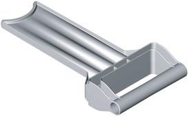
8 8 Deutsch Heben bzw. tragen Sie die Maschine niemals bei laufendem Motor. Schalten Sie das Gerät aus, warten Sie bis das Schneidwerk stoppt und ziehen Sie den Netzstecker, immer wenn Sie den Arbeitsbereich verlassen. Kippen Sie das Gerät während des Betriebes nicht. Setzen Sie das Gerät nicht dem Regen aus. Bewahren Sie das Gerät nur an einem trockenen Ort auf. Wartung und Lagerung Wenn das Gerät wegen Servicearbeit, Überprüfung, Aufbewahrung oder Zubehörwechsel außer Betrieb genommen wird, schalten Sie dieses aus, ziehen den Stecker aus der Steckdose und lassen das Gerät abkühlen. Stellen Sie vor jeder Inspektion oder Justierung etc. sicher, dass alle beweglichen Teile stillstehen. Pflegen Sie das Gerät und halten Sie es sauber. Überprüfen Sie die Maschine und ersetzen Sie sicherheitshalber abgenutzte oder beschädigte Teile. Stellen Sie sicher, dass auszuwechselnde Teile von Bosch stammen. Falls ein Verlängerungskabel verwendet wird, darf es nicht schwächer als das am Gerät angebrachte Netzkabel sein. Überprüfen Sie die Versorgungsleitungen und das Verlängerungskabel regelmäßig auf Beschädigung oder Zeichen von Alterung. Verwenden Sie das Gerät nicht, wenn die Kabel beschädigt sind. Denken Sie beim Einstellen des Schneidwerks daran, dass zwar die Stromzufuhr des Motors durch die Zwangsabschaltung unterbrochen ist und der Motor nicht eingeschaltet werden kann, dass sich das Schneidwerk aber trotzdem bewegt, wenn der Motor mit der Hand gedreht wird. Versuchen Sie keinesfalls die Zwangsabschaltung außer Kraft zu setzen. Funktionsbeschreibung Lesen Sie alle Sicherheitshinweise und Anweisungen. Versäumnisse bei der Einhaltung der Sicherheitshinweise und Anweisungen können elektrischen Schlag, Brand und/oder schwere Verletzungen verursachen. Bestimmungsgemäßer Gebrauch Das Gerät ist bestimmt zum kompostgerechten Zerkleinern von faserigen und holzigen Abfällen aus Haus- und Hobbygärten. Die Fangbox ist bestimmt zur Aufnahme des gehäckselten Materials und zur Aufnahme und Lagerung von Einfülltrichter und Nachschieber. Die Fangbox sollte nicht für andere Zwecke verwendet werden. Lieferumfang Nehmen Sie das Gerät vorsichtig aus der Verpackung und prüfen Sie, ob die nachfolgenden Teile vollständig sind: Leise-Häcksler Einfülltrichter Nachschieber Fangbox Betriebsanleitung Wenn Teile fehlen oder beschädigt sind, wenden Sie sich bitte an Ihren Händler. Die Maschine wiegt im vollständig zusammengebauten Zustand etwa 30,5 31,3 kg. Holen Sie bei Bedarf Hilfe, um die Maschine aus der Verpackung zu nehmen.
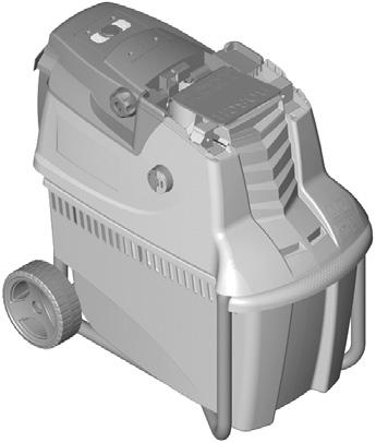
9 Deutsch 9 Abgebildete Komponenten Die Nummerierung der abgebildeten Komponenten bezieht sich auf die Darstellung des Gerätes auf der Grafikseite. 1 Fahrgestell 2 Netzstecker** 3 Lüftungsschlitze 4 Grüne Taste 5 Rote Stopp -Taste 6 Gelbe Taste 7 Nachschieber 8 Einfülltrichter 9 Feststellknopf 10 Einstellknopf 11 Fangbox 12 Seriennummer 13 Schneidwerkabdeckung 14 LED-Anzeige (nur AXT 23 TC/25 TC) 15 Andruckplatte 16 Schneidwalze ** länderspezifisch Abgebildetes oder beschriebenes Zubehör gehört nicht zum Standard-Lieferumfang. Das vollständige Zubehör finden Sie in unserem Zubehörprogramm. Technische Daten Leise-Häcksler AXT 22 D AXT 25 D AXT 23 TC AXT 25 TC Sachnummer 3600H H H H Leistungsaufnahme, S 6 (40/60 s) 1) W Leistungsaufnahme, S 1 W Leerlaufdrehzahl min Schneidsystem Fräswalze Fräswalze Turbine-Cut Turbine-Cut Max. Materialdurchsatz kg/h 180 2) 190 2) 215 2) 230 2) Max. Astdurchmesser mm 38 2) 40 2) 42 2) 45 2) Fangbox l Gewicht entsprechend EPTA-Procedure 01/2003 kg 31,3 31,3 30,5 30,5 Schutzklasse /I /I /I /I 1) Die Betriebsart S 6 (40 %) bezeichnet ein Belastungsprofil, das 40 s Belastung und 60 s Leerlauf annimmt. Für den praktischen Einsatz ist Dauerbetrieb zulässig. 2) Je nach Beschaffenheit des Häckselgutes. Geräusch-/Vibrationsinformation Messwerte ermittelt entsprechend 2000/14/EG (1,60 m Höhe, 1 m Abstand). Der A-bewertete Geräuschpegel des Gerätes beträgt typischerweise: Schalldruckpegel 68 db(a); garantierter Schallleistungspegel niedriger als 92 db(a). Unsicherheit K =3 db. Konformitätserklärung Wir erklären in alleiniger Verantwortung, dass das unter Technische Daten beschriebene Produkt mit den folgenden Normen oder normativen Dokumenten übereinstimmt: EN 60335, EN gemäß den Bestimmungen der Richtlinien 2004/108/EG, 98/37/EG (bis ), 2006/42/EG (ab ), 2000/14/EG.
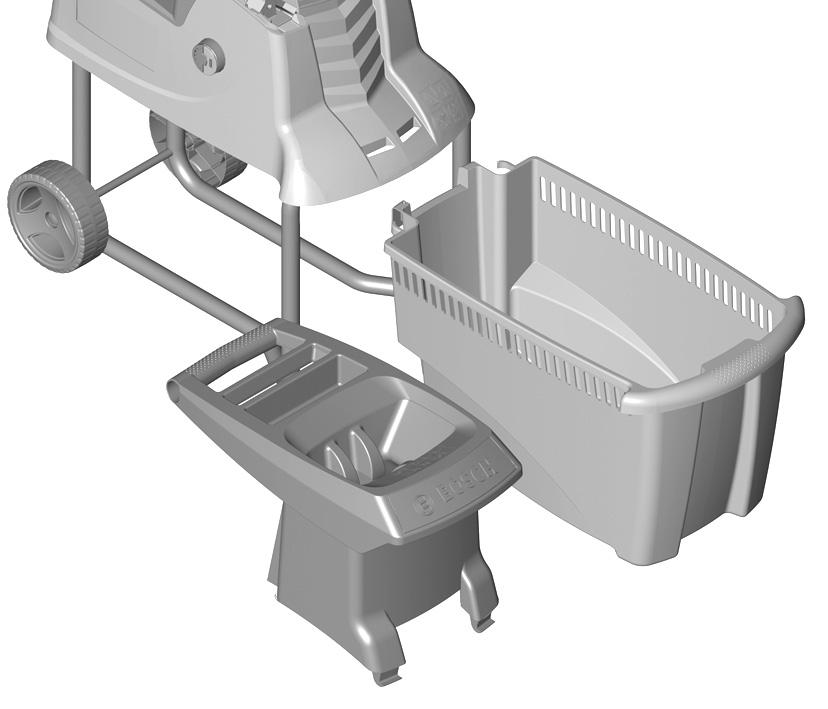
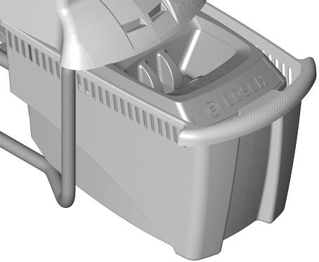
10 10 Deutsch 2000/14/EG: Gemessener Schallleistungspegel 89 db(a). Bewertungsverfahren der Konformität gemäß Anhang V. Technische Unterlagen bei: Bosch Lawn and Garden Ltd., PT-LG/EAE, Stowmarket, Suffolk IP14 1EY, England Leinfelden, den Dr. Egbert Schneider Senior Vice President Engineering Dr. Eckerhard Strötgen Head of Product Certification Kabelverbindungen sollten trocken sein und nicht auf dem Boden liegen. Zur Erhöhung der Sicherheit wird empfohlen, einen FI-Schalter (RCD) mit einem Fehlerstrom von maximal 30 ma zu benutzen. Dieser FI- Schalter sollte vor jeder Benutzung überprüft werden. Wenn die Anschlussleitung beschädigt ist, darf sie nur von einer autorisierten Bosch-Werkstatt repariert werden. Bei der Verwendung von Kabeltrommeln müssen diese ausgerollt sein. Robert Bosch GmbH, Power Tools Division D Leinfelden-Echterdingen Montage Zu Ihrer Sicherheit Achtung! Vor Wartungs- oder Reinigungsarbeiten das Gerät ausschalten und den Netzstecker ziehen. Gleiches gilt, wenn das Stromkabel beschädigt, angeschnitten oder verwickelt ist. Netzspannung beachten: Die Spannung der Stromquelle muss mit den Angaben auf dem Typenschild des Gerätes übereinstimmen. Mit 230 V gekennzeichnete Geräte können auch an 220 V/240 V betrieben werden. Der Stromkreis muss mindestens wie folgt abgesichert sein: AXT 22 D/25 D/23 TC/25 TC = 16 A Ein Verlängerungskabel mit zu kleinem Leiterquerschnitt verursacht eine deutliche Verringerung der Leistungsfähigkeit des Gerätes. Bei Kabeln bis 25 m Länge ist ein Leiterquerschnitt von mindestens 3 x 1,5 mm 2 erforderlich, bei Kabeln über 25 m Länge muss der Leiterquerschnitt mindestens 2,5 mm 2 betragen. VORSICHT: Nicht vorschriftsmäßige Verlängerungskabel können gefährlich sein. Verlängerungskabel, Stecker und Kupplung müssen wasserdichte, für den Außenbereich zugelassene Ausführungen sein. Montage Nehmen Sie das Gerät aus der Verpackung. (siehe Bilder A D) Montage des Einfülltrichters E F Schwenken Sie die Schneidwerkabdeckung 13 nach hinten. Hängen Sie den Einfülltrichter 8 in das Gerät ein. Drehen Sie den roten Feststellknopf 9 im Uhrzeigersinn, um den Einfülltrichter 8 zu arretieren. Betrieb Inbetriebnahme G Stellen Sie das Gerät immer auf festem, waagerechtem Untergrund auf. Kippen oder bewegen Sie das Gerät während des Betriebes nicht. Der Motor läuft nach dem Ausschalten nach! Befreien Sie Wurzelballen von Erde. Fremdkörper wie Steine, Glas, Metalle, Textilien und Kunststoffe dürfen nicht in den Einfülltrichter 8 gelangen. Andernfalls kann die Schneidwalze 16 beschädigt werden. Der Einfülltrichter 8 muss leer sein.
11 Deutsch 11 Einschalten Drücken Sie die grüne Taste 4. Ausschalten Drücken Sie die rote Stopp -Taste 5. Wiederanlaufschutz Das Gerät wird nach einem Netzausfall abgeschaltet. Bei Aktivierung der Energieversorgung kann sich das Gerät nicht automatisch wiedereinschalten. Rücklauf Drücken und halten Sie die gelbe Taste 6, um die Drehrichtung umzukehren. Die Schneidwalze 16 läuft entgegengesetzt und befreit dadurch blockiertes Material. Überlastschutz Zu hohe Belastung (z. B. Blockieren der Schneidwalze 16) führt nach einigen Sekunden zum Stillstand des Gerätes. Drücken und halten Sie die gelbe Taste 6 um das blockierte Schneidwerk zu befreien. Lässt sich die Blockierung nicht beseitigen, muss die Andruckplatte 15 vom Schneidwerk entfernt werden. Der Einstellknopf 10 muss dabei geringfügig gegen den Uhrzeigersinn gedreht werden, bis das blockierte Material frei ist. Die Andruckplatte 15 bedarf anschließend einer Einstellung (siehe Andruckplatte nachstellen ). Arbeitshinweise Tragen Sie während der Benutzung des Gerätes immer Schutzbrille, Gehörschutz und Schutzhandschuhe. Prüfen Sie vor Gebrauch stets die richtige Montage der Fangbox und des Einfülltrichters. Das Gerät ist mit Sensoren ausgestattet. Wenn die Fangbox 11 und der Einfülltrichter 8 nicht richtig positioniert sind, startet das Gerät nicht und ein Signalton ertönt (bei AXT 23 TC/25 TC blinken zusätzlich die 2 LEDs 14). Führen Sie das Häckselgut zu. Eingeschobenes Material wird durch die Schneidwalze 16 selbsttätig eingezogen. Aus dem Gerät ragendes, längeres Häckselgut kann beim Einziehen rutenartig ausschlagen; halten Sie daher einen ausreichenden Sicherheitsabstand ein! Führen Sie immer nur soviel Material ein, dass der Einfülltrichter 8 nicht verstopft. Häckseln Sie welke, feuchte und bereits mehrere Tage gelagerte Gartenabfälle im Wechsel mit Ästen. Dies verhindert ein Zusetzen der Schneidwalze 16. Häckseln Sie keine weichen Abfälle ohne feste Konsistenz, wie z. B. Küchenabfälle, sondern kompostieren Sie diese direkt. Achten Sie darauf, dass das gehäckselte Material frei aus dem Auswurfschacht fallen kann Rückstaugefahr! Die Lüftungsschlitze 3 dürfen nicht durch gehäckseltes Material verdeckt werden. Vermeiden Sie ein Blockieren im Auswurfschacht, da dies zum Rückschlag von Häckselgut im Einfülltrichter 8 führen kann. Hinweise zum Häckseln Je nach Art, Alter und Trockenheit des Holzes sind Äste mehr oder weniger schwierig zu häckseln. Optimale Ergebnisse erzielen Sie, wenn Sie frische Äste kurz nach dem Schnitt häckseln. Weiche Gartenabfälle sollten in kleinen Mengen gehäckselt werden, insbesondere wenn das Häckselgut nass ist. Blockierungen können durch periodisches Häckseln von Ästen vermieden werden. Andruckplatte nachstellen H Die Andruckplatte 15 ist werksseitig justiert und bedarf vor der ersten Inbetriebnahme keiner Einstellung. Das Nachstellen der Andruckplatte 15 ist aufgrund von Verschleiß notwendig (z. B. wenn Häckselgut wie Äste, kettenartig zusammen hängen und nicht einwandfrei gehäckselt werden).
12 12 Deutsch Drehen Sie bei laufendem Motor den Einstellknopf 10 in kleinen Schritten im Uhrzeigersinn, bis ein leichtes Schleifgeräusch hörbar wird (die Schneidwalze 16 schleift die Andruckplatte 15 auf den richtigen Abstand, wobei kleine Aluminiumspäne aus der Auswurföffnung herausfallen). Stellen Sie nur soweit wie erforderlich nach, da ansonsten die Andruckplatte 15 unnötigem Verschleiß ausgesetzt wäre. Fehlersuche Die folgende Tabelle zeigt Fehlersymptome auf und wie Sie Abhilfe schaffen können, wenn Ihre Maschine einmal nicht richtig arbeitet. Wenn Sie damit das Problem nicht lokalisieren und beseitigen können, wenden Sie sich an Ihre Service-Werkstatt. Achtung! Vor Wartungs- oder Reinigungsarbeiten das Gerät ausschalten und den Netzstecker ziehen. Gleiches gilt, wenn das Stromkabel beschädigt, angeschnitten oder verwickelt ist. Symptome Mögliche Ursache Abhilfe Maschine läuft nicht Fangbox nicht richtig montiert Fangbox richtig montieren Einfülltrichter nicht richtig montiert Einfülltrichter richtig montieren Signalton ertönt (bei AXT 23 TC/25 TC blinken zusätzlich zwei LEDs) und Maschine startet nicht Eine LED blinkt (bei AXT 23 TC/25 TC) Häckselgut wird nicht eingezogen Häckselgut wird nicht vollständig gehäckselt und hängt kettenartig zusammen Steckdose defekt Verlängerungskabel beschädigt Sicherung hat ausgelöst Fangbox/Einfülltrichter nicht richtig montiert Keine; das Blinken der LED ist korrekt; die Maschine ist an die Stromversorgung angeschlossen und betriebsbereit Häckselgut ist nass und weich Häckselgut klemmt in der Maschine Andruckplatte muss nachgestellt werden Andere Steckdose benutzen Kabel überprüfen, ev. austauschen Sicherung wechseln Stellen Sie sicher, dass die Fangbox richtig positioniert ist Stellen Sie sicher, dass der Einfülltrichter richtig positioniert und durch Drehen des roten Feststellknopfs im Uhrzeigersinn festgeklemmt ist Benutzen Sie den Nachschieber um das Häckselgut in die Maschine nachzuschieben Blockierendes Häckselgut entfernen (tragen Sie immer Gartenhandschuhe) Betätigen Sie die Umkehrtaste (siehe Rücklauf ) siehe Andruckplatte nachstellen
13 Deutsch 13 Wartung und Service Wartung und Reinigung Achtung! Vor Wartungs- oder Reinigungsarbeiten das Gerät ausschalten und den Netzstecker ziehen. Gleiches gilt, wenn das Stromkabel beschädigt, angeschnitten oder verwickelt ist. Tragen Sie immer Schutzhandschuhe, wenn Sie mit dem Gerät arbeiten oder Wartungs-/ Reinigungsarbeiten durchführen möchten. Hinweis: Führen Sie die folgenden Wartungsarbeiten regelmäßig aus, damit eine lange und zuverlässige Nutzung gewährleistet ist. Die Maschine regelmäßig auf offensichtliche Mängel wie lose oder beschädigte Messer, lose Verbindungen und abgenutzte oder beschädigte Teile untersuchen. Prüfen Sie, ob Abdeckungen und Schutzvorrichtungen unbeschädigt und richtig angebracht sind. Führen Sie vor der Benutzung eventuell notwendige Wartungs- oder Reparaturarbeiten durch. Sollte das Gerät trotz sorgfältiger Herstellungsund Prüfverfahren einmal ausfallen, ist die Reparatur von einer autorisierten Kundendienststelle für Bosch-Gartengeräte ausführen zu lassen. Geben Sie bei allen Rückfragen und Ersatzteilbestellungen bitte unbedingt die 10-stellige Sachnummer laut Typenschild des Gerätes an. Andruckplatte ausbauen I Achtung! Vor Wartungs- oder Reinigungsarbeiten das Gerät ausschalten und den Netzstecker ziehen. Gleiches gilt, wenn das Stromkabel beschädigt, angeschnitten oder verwickelt ist. Tragen Sie immer Schutzhandschuhe, wenn Sie mit dem Gerät arbeiten oder Wartungs-/ Reinigungsarbeiten durchführen möchten. Bei normaler Nutzung und Nachstellung gemäß der Anweisung, haben die Schneidwalze 16 und die Andruckplatte 15 eine mehrjährige Lebensdauer. Gehen Sie zum Ausbau, zur Reinigung oder zum Austausch der Andruckplatte 15 wie folgt vor: Entfernen Sie wie im Bild dargestellt die Schraube der Andruckplatte vollständig. Heben Sie die Andruckplatte 15 mit einem Schraubendreher heraus. Der Zusammenbau erfolgt in umgekehrter Reihenfolge, wobei die Andruckplatte 15 anschließend nachgestellt werden muss (siehe Andruckplatte nachstellen ). Nach dem Arbeitsvorgang/Aufbewahrung Der Häcksler darf nicht mit Hochdruckreinigern oder fließendem Wasser gereinigt werden. Das Äußere der Maschine gründlich mit einer weichen Bürste und einem Tuch reinigen. Kein Wasser und keine Lösungs- oder Poliermittel verwenden. Sämtliche Grasanhaftungen und Partikel entfernen, insbesondere von den Lüftungsschlitzen 3. Lagern Sie das Gerät an einem trockenen Ort. Stellen Sie keine anderen Gegenstände auf das Gerät. Das Kabel kann, wie dargestellt, am Häcksler aufbewahrt werden (nur UK). (siehe Bild J) Der Häcksler kann, gemäß Bild B, nach Demontage des Einfülltrichters gelagert werden (siehe auch Montage des Einfülltrichters ). Kundendienst und Kundenberatung Der Kundendienst beantwortet Ihre Fragen zu Reparatur und Wartung Ihres Produkts sowie zu Ersatzteilen. Explosionszeichnungen und Informationen zu Ersatzteilen finden Sie auch unter: Das Bosch-Kundenberater-Team hilft Ihnen gerne bei Fragen zu Kauf, Anwendung und Einstellung von Produkten und Zubehören. das Internetportal für Heimwerker und Gartenfreunde. das komplette Service-Angebot der Deutschen Heimwerker Akademie.
14 14 Deutsch Deutschland Robert Bosch GmbH Servicezentrum Elektrowerkzeuge Zur Luhne Kalefeld Willershausen Tel. Kundendienst: +49 (1805) Fax: +49 (1805) Servicezentrum.Elektrowerkzeuge@de. bosch.com Tel. Kundenberatung: +49 (1803) Fax: +49 (711) kundenberatung.ew@de.bosch.com Österreich Tel.: +43 (01) Fax: +43 (01) service.elektrowerkzeuge@at.bosch.com Schweiz Tel.: +41 (044) Fax: +41 (044) Luxemburg Tel.: +32 (070) Fax: +32 (070) outillage.gereedschap@be.bosch.com Entsorgung Elektrowerkzeuge, Zubehör und Verpackungen sollen einer umweltgerechten Wiederverwertung zugeführt werden. Nur für EU-Länder: Werfen Sie Elektrowerkzeuge nicht in den Hausmüll! Gemäß der Europäischen Richtlinie 2002/96/EG über Elektro- und Elektronik-Altgeräte und ihrer Umsetzung in nationales Recht müssen nicht mehr gebrauchsfähige Elektrowerkzeuge getrennt gesammelt und einer umweltgerechten Wiederverwertung zugeführt werden. Änderungen vorbehalten.
15 English 15 en Safety Notes Warning: Read these instructions carefully, be familiar with the controls and proper use of the machine. Please keep the instructions safe for later use. Before using for the first time, ask for a practical demonstration. Explanation of symbols on the machine General hazard safety alert. STOP Read instruction manual. Before handling the cutter, switch off and remove the plug from the mains supply. If the cable is damaged or cut through while working, do not touch the cable but immediately remove the plug from the mains supply. Never use the machine with a damaged cable. Wear protective gloves, sturdy shoes and long trousers. Danger rotating blade. Keep hands and feet out of openings while the machine is running. Pay attention that bystanders are not injured through foreign objects thrown from the machine. Keep bystanders a safe distance away from the machine. Wait until all machine components have completely stopped before touching them. Wear eye protection. Wear ear protection. Do not use the machine in the rain or leave it outdoors when it is raining. Do not stand on the collection box. Operation During operation, do not reach into the chute assembly 8. The machine runs on for a few seconds after being switched off. Never allow children or people unfamiliar with these instructions to use the machine. Local regulations may restrict the age of the operator. When not in use store the machine out of reach of children. This tool is not intended for use by persons (including children) with reduced physical, sensory or mental capabilities, or lack of experience and knowledge, unless they have been given supervision or instruction concerning use of the appliance by a person responsible for their safety. Children should be supervised to ensure that they do not play with the appliance. Before switching on, the machine must be assembled according to the enclosed instructions. It is recommended for increased electrical safety to use a Residual Current Device (RCD) with a tripping current of not more than 30 ma. Always check your RCD every time you use it. Use only extension cables that are intended for outdoor use and are protected against splashes of water. Do not touch the plug or socket with wet hands. Do not run over, crush or pull the power supply cable or extension lead, otherwise it may be damaged. Protect the cable from heat, oil and sharp edges. Other persons and animals should remain at a distance of 3 metres or more when the machine is being used. The operator is responsible for third persons in the working area.
16 16 English Bosch can assure flawless functioning of the machine only when original accessories are used. Become familiar with the instruction manual before attempting to operate this machine. Avoid wearing loose-fitting clothing, hanging cords or ties. Only operate the machine in open space (e. g. not too close to a wall or other fixed objects) and on a firm, level surface. Do not operate the machine on paved or gravel surface where ejected material could cause injury. Before starting the machine, check that all screws, nuts, bolts and other fasteners are properly secured and that guards and screens are in place. Replace damaged or unreadable warning and operating labels. Before starting the machine, make certain that the chute assembly is empty. Keep your face and body away from the chute assembly. Do not allow hands or any other part of the body or clothing inside the chute assembly, discharge chute or near any moving part. Switch off the machine before attaching or removing the bag. Keep proper balance and footing at all times. Do not overreach. Never stand at a higher level than the base of the machine when feeding material. Always stand clear of the discharge zone when operating the machine. When feeding material into the machine be extremely careful that pieces of metal, rocks, bottles, cans or other foreign objects are not included. If the cutting mechanism strikes any foreign object or if the machine should start making any unusual noise or vibration, immediately switch off and allow the cutter to stop. Remove the plug from the mains supply and take the following steps: Inspect for damage. Replace or repair any damaged parts. Check for and tighten any loose parts. Do not attempt to repair the machine unless you are qualified to do so. Do not allow processed material to build up in the discharge zone; this may prevent proper discharge which can result in kickback of material through the chute assembly. If the machine becomes clogged, switch off and allow the cutter to stop. Remove the plug from the mains supply before clearing debris. Check if guards and protective devices are undamaged and properly mounted. Before using, carry out possibly necessary maintenance and repairs. Do not tamper with the motor speed control settings. Contact a Bosch approved service agent if a problem exists. Keep the motor cooling vents clean of debris and other accumulations to prevent damage to the motor or possible fire. Never pick up or carry the machine while the motor is running. Switch off, allow the cutter to stop and remove the plug from the mains supply whenever you leave the work area. Do not tilt the machine while it is running. Do not expose the machine to rain. Only store the machine in a dry place. Maintenance and Storage When the machine is stopped for servicing, inspection, or storage, or to change an accessory, switch off and remove the plug from the mains supply and allow the machine to cool. Make sure that all moving parts have come to a complete stop before making any inspections, adjustments, etc. Maintain the machine with care and keep it clean. Examine the machine and replace worn or damaged parts for safety. Ensure replacement parts fitted are Bosch approved. If an extension cord is used it shall not be of lighter grade than the supply cord already fitted to the machine.
17 English 17 Check the supply and any extension cord regularly for damage or signs of ageing. Do not use the machine, if the cords are damaged. When servicing the cutter be aware that, even though the motor will not start due to the interlock feature of the guard, the cutter can still be moved if the motor is turned by hand. Never attempt to override the interlock feature of the guard. Functional Description Read all safety warnings and all instructions. Failure to follow the warnings and instructions may result in electric shock, fire and/or serious injury. Intended Use The product is intended for cutting of fibrous and woody garden waste for composting. The collection box is intended for collecting the material cut, and for storing the chute assembly and prodder. The collection box should not be used for other purposes. Product Features The numbering of the components shown refers to the representation of the machine on the graphic pages. 1 Undercarriage 2 Power plug** 3 Ventilation slots 4 Green button 5 Red stop button 6 Yellow button 7 Prodder 8 Chute assembly 9 Clamping knob 10 Adjustment knob 11 Collection box 12 Serial number 13 Blade cover plate 14 LED indicator (AXT 23 TC/25 TC only) 15 Pressure plate 16 Cutting roller ** country specific Accessories shown or described are not part of the standard delivery scope of the product. A complete overview of accessories can be found in our accessories program. Delivery Scope Carefully remove the machine from its packaging and check if the following parts are complete: Quiet-shredder Chute assembly Prodder Collection box Operating instructions When parts are missing or damaged, please contact your dealer. When fully assembled the machine weighs approximately kg. If necessary, obtain assistance to remove from packaging.
18 18 English Technical Data Quiet-shredder AXT 22 D AXT 25 D AXT 23 TC AXT 25 TC Article number 3600H H H H Power consumption, S 6 (40/60 s) 1) W Power consumption, S 1 W No-load speed min Cutting system Drum Drum Turbine Turbine Capacity, max. kg/h 180 2) 190 2) 215 2) 230 2) Branch diameter, max. mm 38 2) 40 2) 42 2) 45 2) Collection box l Weight according to EPTA-Procedure 01/2003 kg Protection class /I /I /I /I 1) The S 6 operating mode (40 %) indicates a load profile of 40 s load and 60 s idle time. For practical application, continuous operation is permitted. 2) Depending on the hardness of the wood. Noise/Vibration Information Measured values determined according to 2000/14/EC (1.60 m height, 1.0 m distance away). Typically the A-weighted noise levels of the product are: Sound pressure level 68 db(a); Guaranteed sound power level lower than 92 db(a). Uncertainty K =3 db. Declaration of Conformity We declare under our sole responsibility that the product described under Technical data is in conformity with the following standards or standardization documents: EN 60335, EN according to the provisions of the directives 2004/108/EC, 98/37/EC (until 28 Dec 2009), 2006/42/EC (from 29 Dec 2009), 2000/14/EC. 2000/14/EC: Measured sound power level 89 db(a). Conformity assessment procedure according to Annex V. Technical file at: Bosch Lawn and Garden Ltd., PT-LG/EAE, Stowmarket, Suffolk IP14 1EY, England Leinfelden, Dr. Egbert Schneider Senior Vice President Engineering Robert Bosch GmbH, Power Tools Division D Leinfelden-Echterdingen Assembly Dr. Eckerhard Strötgen Head of Product Certification For Your Safety Warning! Switch off, remove plug from mains before adjusting, cleaning or if cable is cut, damaged or entangled. Observe correct mains voltage: The voltage of the power source must agree with the voltage specified on the nameplate of the unit. Equipment marked with 230 V can also be connected to 220 V or 240 V.
19 English 19 The circuit must at least be protected as follows: AXT 22 D/25 D/23 TC/25 TC = 16 A An extension cable with a cross section that is too small causes a distinct reduction in the performance capabilities of the machine. For cables to 25 m in length, a cross section of at least 3x1.5mm 2 is required, for cables more than 25 m in length, the cross section must be at least 2.5 mm 2. WARNING! Inadequate extension cables can be dangerous. Extension cable, plug and socket must be of watertight construction and intended for outdoor use. Cable connections should be kept dry and off ground. It is recommended for increased electrical safety to use a Residual Current Device (RCD) with a tripping current of not more than 30 ma. Always check your RCD every time you use it. If the supply cord is damaged, it must be replaced by a Bosch Service Centre. When using cable drums, these must be completely unreeled. Products sold in GB only: Your product is fitted with an BS 1363/A approved electric plug with internal fuse (ASTA approved to BS 1362). If the plug is not suitable for your socket outlets, it should be cut off and an appropriate plug fitted in its place by an authorised customer service agent. The replacement plug should have the same fuse rating as the original plug. The severed plug must be disposed of to avoid a possible shock hazard and should never be inserted into a mains socket elsewhere. Assembly Remove the machine from the package. (see figures A D) Assemble the chute E F Lift back blade cover plate 13. Hook in chute assembly 8 to the machine. Turn red clamping knob 9 fully clockwise to lock the chute 8 in place. Operation Starting Operation G Always place the machine on firm level ground. During operation, do not tilt or move. The motor will coast after switching off! Remove earth from roots. Foreign material such as stones, glass, metals, fabrics or plastics must not enter the chute assembly 8. Otherwise this could damage the cutting roller 16. The chute assembly 8 must be empty. Starting Press green button 4. Stopping Press red stop button 5. Restarting Protection A mains failure causes machine to switch off. The machine cannot restart on its own when the power returns. Return Motion Press and hold the yellow button 6 to reverse the feed. The cutting roller 16 runs backward and frees jammed material. Overload Protection Overloading (e. g. blocking of the cutting roller 16) causes the machine to stop after a few seconds. Press and hold the yellow button 6 to reverse the cutter to unblock. If the blockage cannot be cleared the pressure plate 15 will need to moved away from the cutter. The adjustment knob 10 will need to be turned a anti clock wise direction a small amount until the jammed material is clear. The pressure plate 15 will need adjustment (see Pressure Plate Adjustment ).
20 20 English Working Advice Wear eye protection, hearing protection and safety gloves at all times while operating the machine. Always check before use that the collection box and chute assembly are fitted correctly. The machine is fitted with sensors, unless the collection box 11 is fitted correctly and the chute assembly 8 is correctly positioned, the machine will not start and the buzzer beeps (on AXT 23 TC/25 TC also the 2 LEDs 14 flash). Insert the material to be shredded. The material will be fed by the cutter roller 16 without further assistance. Longer material standing out from the machine could lash out when being pulled in by the knives! Please keep at safe distance! Only insert as much material so that the chute assembly 8 will not be blocked up. Shred withered, moist material and garden waste which has been stored for some days alternately with branches. This prevents the cutting roller 16 from clogging. Do not fill soft waste such as kitchen rubbish into the shredder but compost directly. Take care that the shredded material can fall freely from the discharge chute danger of backing up! The ventilation slots 3 must not be covered by the shredded material. Avoid blocking the discharge chute with shredded material as this could result in kickback of material through the chute assembly 8 opening. Pressure Plate Adjustment H The pressure plate 15 is factory adjusted and does not require adjustment before the first use. Adjustment of the pressure plate 15 is necessary as a result of wear (shredded material, e. g. branches, hangs together as a chain and is not properly cut through). With the motor running, turn the adjustment knob 10 a small amout at a time in a clock wise direction until a light grinding sound can be heard (the cutting roller 16 cuts the pressure plate 15 to the proper clearance, and some small aluminium shavings fall out of the ejection chute). Readjust only to the required extent, otherwise the pressure plate 15 could wear unnecessarily. Advice on Shredding Branches become harder to shred depending on the type, age and dryness of the wood. For best results, shred fresh branches soon after they have been cut. Soft garden waste should be shredded in smaller loads, particularly when wet. Any blockages can be avoided by intermittently shredding branches.
21 English 21 Troubleshooting The following chart lists problem symptoms, possible causes and corrective action, if your machine does not operate properly. If these do not identify and correct the problem, contact your service agent. Warning! Switch off, remove plug from mains before adjusting, cleaning or if cable is cut, damaged or entangled. Problem Possible Cause Corrective Action Machine fails to operate Collection box not fitted correctly Fit collection box correctly Machine beeps (also two lights on AXT 23 TC/25 TC) and does not start One flashing light on AXT 23 TC/25 TC The material to be shredded is not pulled in Shredded material is not completely separated and hangs together as a chain Chute assembly not fitted correctly Mains socket faulty Extension cable damaged Fuse faulty/blown Collection box/chute is not correctly assembled None, this is ok, machine is pluged in and ready to use Material to be shredded is wet and soft Jammed material in the machine Pressure plate requires adjustment Fit chute assembly correctly Use another socket Inspect cable, replace if damaged Replace fuse Ensure the collection box is in position Ensure the chute assembly is in position and clamped by turning the clamping knob (red) fully clockwise Use the prodder to push the material into the machine Clear jammed material (always wear gardening gloves) Use the reverse button (see Return Motion ) see Pressure Plate Adjustment Maintenance and Service Maintenance and Cleaning Warning! Switch off, remove plug from mains before adjusting, cleaning or if cable is cut, damaged or entangled. Always wear protective gloves when using, adjusting or cleaning the machine. Note: To ensure long and reliable service, carry out the following maintenance regularly. Regularly check for obvious defects such as loose, dislodged or damaged blades, loose fixings, and worn or damaged components.
22 22 English Check that covers and guards are undamaged and correctly fitted. Carry out necessary maintenance or repairs before using. If the machine should happen to fail despite the care taken in manufacture and testing, repair should be carried out by an authorised customer service agent for Bosch garden products. In all correspondence and spare parts orders, please always include the 10-digit article number given on the type plate of the machine. Removing the Pressure Plate I Warning! Switch off, remove plug from mains before adjusting, cleaning or if cable is cut, damaged or entangled. Always wear protective gloves when using, adjusting or cleaning the machine. The cutting roller 16 and the pressure plate 15 have a life expectancy of several years under normal usage and when adjusted according to instructions. Use the following to remove the pressure plate 15, to aid cleaning or for replace: Unscrew the pressure plate screw fully as shown. Lift out pressure plate 15 using screw driver. Fit in the reverse order, the pressure plate 15 will require adjustment (see Pressure Plate Adjustment ). After Use/Storage The shredder must not be cleaned with highpressure cleaners or running water. Clean the exterior of the machine thoroughly using a soft brush and cloth. Do not use water, solvents or polishes. Remove all grass and debris, especially from the ventilation slots 3. Store the machine in a dry place. Do not place other objects on top of the machine. Cable can be stored on the shredder as shown (only UK). (see figure J) The shredder can be stored as in figure B by removing the chute assembly (see also Assemble the chute ). After-sales Service and Customer Assistance Our after-sales service responds to your questions concerning maintenance and repair of your product as well as spare parts. Exploded views and information on spare parts can also be found under: Our customer consultants answer your questions concerning best buy, application and adjustment of products and accessories. Great Britain Robert Bosch Ltd. (B.S.C.) P.O. Box 98 Broadwater Park North Orbital Road Denham Uxbridge UB 9 5HJ Tel. Service: +44 (0844) Fax: +44 (0844) SPT-Technical.de@de.bosch.com Ireland Origo Ltd. Unit 23 Magna Drive Magna Business Park City West Dublin 24 Tel. Service: +353 (01) Fax: +353 (01) Australia, New Zealand and Pacific Islands Robert Bosch Australia Pty. Ltd. Power Tools Locked Bag 66 Clayton South VIC 3169 Customer Contact Center Inside Australia: Phone: +61 (01300) Fax: +61 (01300) Inside New Zealand: Phone: +64 (0800) Fax: +64 (0800) Outside AU and NZ: Phone: +61 (03)
23 English 23 Republic of South Africa Customer service Hotline: +27 (011) Gauteng BSC Service Centre 35 Roper Street, New Centre Johannesburg Tel.: +27 (011) Fax: +27 (011) bsctools@icon.co.za KZN BSC Service Centre Unit E, Almar Centre 143 Crompton Street Pinetown Tel.: +27 (031) Fax: +27 (031) bsc.dur@za.bosch.com Western Cape BSC Service Centre Democracy Way, Prosperity Park Milnerton Tel.: +27 (021) Fax: +27 (021) bsc@zsd.co.za Bosch Headquarters Midrand, Gauteng Tel.: +27 (011) Fax: +27 (011) rbsa-hq.pts@za.bosch.com Disposal The machine, accessories and packaging should be sorted for environmental-friendly recycling. Only for EC countries: Do not dispose of power tools into household waste! According the European Guideline 2002/96/EC for Waste Electrical and Electronic Equipment and its implementation into national right, power tools that are no longer usable must be collected separately and disposed of in an environmentally correct manner. Subject to change without notice.
24 24 Français fr Consignes de sécurité Attention : Lisez soigneusement ces instructions d utilisation. Familiarisez-vous avec les éléments de commande et l utilisation correcte de l appareil. Conservez les instructions d utilisation pour une utilisation ultérieure. Demandez une démonstration pratique avant la première mise en service. Explication des symboles se trouvant sur la machine Indications générales sur d éventuels dangers. Lire les instructions d utilisation. STOP Attendez l arrêt total de tous les éléments de l appareil avant de les toucher. Porter des lunettes de sécurité. Portez une protection acoustique. Ne pas utiliser l appareil par temps de pluie ni l exposer à la pluie. Ne marchez pas sur le bac de récupération. Avant toute intervention sur le mécanisme de coupe, arrêtez l appareil et retirez la fiche de la prise de courant. Au cas où le câble serait endommagé ou coupé lors du travail, ne pas y toucher mais désactiver immédiatement le circuit électrique par l intermédiaire du coupe-circuit correspondant. N utilisez jamais l appareil lorsque le câble est endommagé. Portez toujours des gants de protection, des chaussures fermées et des pantalons longs. Danger : lame en rotation! Ne pas mettre les mains ni les pieds dans l ouverture tant que l appareil est en fonctionnement. Faites attention à ce que les personnes se trouvant à proximité ne soient pas blessées par des projections provenant de la machine. Gardez une distance de sécurité entre l utilisateur de la machine en marche et des personnes se trouvant à proximité. Mode d emploi Ne mettez pas les mains dans l entonnoir 8 durant le fonctionnement. Lorsqu on arrête l appareil, celui-ci continue à tourner pendant quelques secondes encore. Ne jamais laisser un enfant ou une autre personne n ayant pas pris connaissance des instructions d utilisation se servir de la machine. Il est possible que les réglementations locales fixent une limite d âge minimum de l utilisateur. Gardez la machine non utilisée hors de la portée des enfants. Cet appareil n est pas conçu pour être utilisé par des personnes (enfants compris) souffrant d un handicap physique, sensoriel ou mental ou par des personnes n ayant l expérience et/ou les connaissances nécessaires, à moins qu elles ne soient surveillées par une personne responsable de leur sécurité ou qu elles aient été instruites quant au maniement de l appareil. Les enfants doivent être surveillés pour assurer qu ils ne jouent pas avec l appareil. Avant la mise en fonctionnement, l appareil doit être monté conformément aux instructions jointes à l appareil. Pour plus de sécurité, il est recommandé d utiliser un disjoncteur différentiel avec un courant de défaut de 30 ma maximum. Avant chaque utilisation de la machine, contrôler ce disjoncteur différentiel.
25 Français 25 N utilisez que des rallonges autorisées pour l extérieur et étanches aux projections d eau. Ne touchez pas la fiche et la prise de courant avec les mains humides. Ne pas écraser le câble d alimentation ou la rallonge, ni les coincer ou les tirer sous risque de les endommager. Protégez le câble contre la chaleur, l huile et les bords tranchants. Durant le service, aucune autre personne ni animal ne doit se trouver dans un rayon de 3 m autour de l appareil. Dans la zone de travail, l opérateur est responsable vis à vis des tierces personnes. Bosch ne peut garantir un fonctionnement impeccable que si seuls les accessoires Bosch d origine sont utilisés. Familiarisez-vous avec les instructions d utilisation avant de travailler avec l appareil. Ne portez pas de vêtements amples ou de rubans pendants ou de cravates. Faites fonctionner l appareil dans un endroit dégagé et sans objets aux alentours (p. ex. pas trop près d un mur ou d autres objets fixes) sur une surface plane et solide. Ne faites pas fonctionner l appareil sur une surface pavée ou recouverte de graviers. Les déchets éjectés peuvent causer des blessures. Avant la mise en service, contrôlez que toutes les vis, tous les écrous et autres composants de fixation soient correctement fixés et que les dispositifs de protection et de déflexion soient correctement mis en place. Remplacez les plaques d avertissement endommagées ou illisibles. Avant de démarrer, assurez-vous que l entonnoir est libre. Tenez le visage et le corps à distance de l ouverture de l entonnoir. Evitez que les mains et d autres parties du corps ou des vêtements parviennent dans l entonnoir ou dans l ouverture d éjection ou à proximité des pièces en mouvement. Arrêtez l appareil avent d accrocher ou de décrocher le sac de récupération. Veillez à toujours garder une position stable et un bon équilibre. Ne vous penchez pas trop en avant. Durant le remplissage, ne vous mettez pas sur une position plus élevée que celle du pied de l appareil. Lors du travail, gardez une certaine distance par rapport à la zone d éjection. Veillez tout particulièrement à ce qu il n y ait pas de pièces en métal, de pierres, de bouteilles, canettes ou autres corps étrangers parmi les déchets à introduire dans l appareil. Au cas où le mécanisme de coupe heurterait un corps étranger ou que l appareil commencerait à faire des bruits étranges ou à vibrer, arrêtez immédiatement l appareil pour arrêter le couteau. Retirez la fiche de la prise de courant et procédez comme suit : Inspectez le dommage. Remplacez toutes les pièces endommagées ou réparez-les. Contrôlez si des pièces se sont détachées et, le cas échéant, resserrez-les. N essayez jamais de réparer l appareil sauf si vous avez la formation nécessaire. Faites attention à ce que les déchets coupés n obturent pas la zone d éjection ; ceci entrave l éjection des déchets broyés et peut provoquer un contrecoup dans l entonnoir. Quand l appareil est obturé, arrêtez-le et attendez l arrêt complet du couteau. Retirez la fiche de la prise de courant avant d enlever les déchets broyés de l appareil. Vérifiez que les couvercles et les dispositifs de protection ne soient pas endommagés et qu ils soient correctement branchés. Avant d utiliser l appareil, effectuez les travaux d entretien et de réparation éventuellement nécessaires. N essayez pas de modifier la vitesse de rotation du moteur. Lorsqu il y a un problème, contactez le service après-vente Bosch. Tenez les ouïes de ventilation exemptes de résidus ou autres objets afin d éviter un endommagement du moteur ou un incendie éventuel.
IMPORTANT! RETAIN FOR FUTURE REFERENCE PLEASE READ CAREFULLY VIKTIGT! BEHÅLL FÖR FRAMTIDA REFERENS LÄS IGENOM INSTRUKTIONSMANUALEN
 Heart & Stripes Junior Bed Instructions Manual Instruktions Manual IMPORTANT! RETAIN FOR FUTURE REFERENCE PLEASE READ CAREFULLY VIKTIGT! BEHÅLL FÖR FRAMTIDA REFERENS LÄS IGENOM INSTRUKTIONSMANUALEN Thank
SAFETY PRECAUTIONS SPECIFICATIONS
 SAFETY PRECAUTIONS Read the instructions carefully before use and save them for future reference. Before you connect the appliance: Ensure that the voltage rating on the type plate corresponds to your
IMPORTANT! RETAIN FOR FUTURE REFERENCE PLEASE READ CAREFULLY VIKTIGT! BEHÅLL FÖR FRAMTIDA REFERENSLÄS IGENOM INSTRUKTIONSMANUALEN NOGGRANT
 13060 Basic Cot One Instruction Manual Instruktion Manual IMPORTANT! RETAIN FOR FUTURE REFERENCE PLEASE READ CAREFULLY VIKTIGT! BEHÅLL FÖR FRAMTIDA REFERENSLÄS IGENOM INSTRUKTIONSMANUALEN NOGGRANT Thank
SAFETY PRECAUTIONS SPECIFICATIONS
 SAFETY PRECAUTIONS Read the instructions carefully before use and save them for future reference. Before you connect the appliance: Ensure that the voltage rating on the type plate corresponds to your
ARC 32. Tvättställsblandare/Basin Mixer. inr.se
 ARC 32 Tvättställsblandare/Basin Mixer inr.se SE Användning och skötsel Manualen är en del av produkten. Bevara den under hela produktens livscykel. Vi rekommenderar er att noggrant läsa igenom manualen
Installation Instructions
 Installation Instructions (Cat. No. 1794-IE8 Series B) This module mounts on a 1794 terminal base unit. 1. Rotate keyswitch (1) on terminal base unit (2) clockwise to position 3 as required for this type
VASSVIK FIXED STAND SE / ENG
 VASSVIK FIXED STAND SE / ENG SE VIKTIGT Läs noga igenom instruktionerna före användning och spar dessa för framtida bruk. VARNING: Barnets huvud bör inte ligga lägre än barnets kropp. Lägg inte till ytterligare
Joki Joki Air. JCD70-xx JAD90-xx. lasiesta.com. Manual. Betriebsanleitung. Manuel. Manual. Manuale. Gebruiksaanwijzing.
 lasiesta.com LA SIESTA GmbH Im Wiesenweg 4 55270 Jugenheim Germany Tel: +49 6130 9119-19 LA SIESTA Inc. 7355 S.W. 87 th Ave., Ste. 100 Miami, FL 33173 USA Tel: +1 786 401-1138 EN DE FR ES IT NL DA SV FI
Nathi Skötbord Changing unit Table à langer murale Wickeltisch Verschoontafel Puslebord Cambiador de pared Přebalovací pult Fasciatoio
 Nathi Skötbord Changing unit Table à langer murale Wickeltisch Verschoontafel Puslebord Cambiador de pared Přebalovací pult Fasciatoio Пеленальный стол Tested and approved according to SS-EN 12221:2008+A1_2013
SAFETY PRECAUTIONS SPECIFICATIONS
 SAFETY PRECAUTIONS Read the instructions carefully before use and save them for future reference. Before you connect the appliance: Ensure that the voltage rating on the type plate corresponds to your
WALLMEK i Kungälv AB Special tools for auto repairs
 Arbetsinstruktion till 1090-39 för byte av bakvagnsbussning på Golf IV, Audi A3 mfl. 1090-39-05-01 Satsen används med hydraulcylinder samt pressbygel med öppen underdel (1090-69) 1090-39-05-02 1, Rengör
BBT057/ BBC057 BBCD057/ BBT057-NL HOLDEN COLORADO 9/2016+ HOLDEN TRAILBLAZER WD & 4WD Models
 INSTALLATION GUIDE BBT057/ BBC057 BBCD057/ BBT057-NL HOLDEN COLORADO 9/2016+ HOLDEN TRAILBLAZER 2017+ 2WD & 4WD Models Ironman 4x4 BBT/ BBC/ BBCD/BBT057-NL Bull Bars fit to a Holden Colorado 9/2016+ It
Tariff Kit. Installatörshandbok Tariff Kit för NIBE F1330 LEK. Installer manual Tariff Kit for NIBE F1330
 Tariff Kit SE Installatörshandbok Tariff Kit för NIBE F1330 LEK GB DE Installer manual Tariff Kit for NIBE F1330 Installateurhandbuch Tariff Kit für NIBE F1330 IHB 1116-1 031517 Svenska, Installatörshandbok
Installationsanvisning
 Dok. Nr: M847 V: 1.0 2014-01-20 Installationsanvisning 847.01 Constella Försäljning AB Box 10024 781 10 Borlänge SWEDEN Tel: 0243-83140 847 230 V / 120 V 345 W / 324 W 18 mm / s 114 145 (mm) 250 mm kg
Manual. SE Control Omni Dockningsstation GB Control Omni Docking station DE Control Omni Dockstation
 Manual SE Control Omni Dockningsstation GB Control Omni Docking station DE Control Omni Dockstation Innehållsförteckning/Content/Inhalt 1 SVENSKA... 3 1.1 BESKRIVNING... 3 1.2 ANSLUTNING... 3 1.3 MONTERING...
Your No. 1 Workout. MANUAL pro
 Your No. 1 Workout MANUAL pro Innehåll/Contents Svenska Viktigt om säkerhet Specifikationer & delar Rekommenderade övningar 3 5 6-7 2 English Safety instructions Specifications & parts Recommended exercises
Windlass Control Panel v1.0.1
 SIDE-POWER Windlass Systems 86-08950 Windlass Control Panel v1.0.1 EN Installation manual Behåll denna manual ombord! S Installations manual SLEIPNER AB Kilegatan 1 452 33 Strömstad Sverige Tel: +46 525
HANDPUMP H-11 DIRECTIONS FOR USE BRUKSANVISNING GEBRAUCHANWEISUNG
 E-417 HANDPUMP H-11 DIRECTIONS FOR USE BRUKSANVISNING GEBRAUCHANWEISUNG HAND PUMP H-11 Detta är en 2-stegs hydraulpump med ett inbyggt kombinerat låg- och hög- tryckssystem som automatiskt växlar från
LINC MODELL 13. INR SVERIGE AB Kosterögatan 15 SE-211 24 Malmö 13 EN 1428:2005+A1:2008
 LINC MODELL 13 151005 Produkten är anpassad till branschregler Säker Vatteninstallation. INR garanterar produktens funktion om branschreglerna och monteringsanvisningen följs. INR SVERIGE AB Kosterögatan
WALLMEK i Kungälv AB Special tools for auto repairs
 Handhavandeinstruktion till sats 01-00014 för byte av bakvagnsbussningar på Hyundai Santa Fe. Bakaxeln demonteras från sina infästningar och sänks ned med en lyft tills de fasta bultarna i golvet släpper
SAFETY PRECAUTIONS SPECIFICATIONS
 SAFETY PRECAUTIONS Read the instructions carefully before use and save them for future reference. Before you connect the appliance: Ensure that the voltage rating on the type plate corresponds to your
säkerhetsutrustning / SAFETY EQUIPMENT
 säkerhetsutrustning / SAFETY EQUIPMENT Hastighetsvakt / Speed monitor Kellves hastighetsvakter används för att stoppa bandtransportören när dess hastighet sjunker under beräknade minimihastigheten. Kellve
Monteringsanvisning Nödutrymningsbeslag ASSA 179E
 Monteringsanvisning Nödutrymningsbeslag ASSA 179E Denna monteringsanvisning avser nödutrymningsbeslag ASSA 179E med artikelnummer 364371 i kombination med låshus Abloy EL580 med artikelnummer EL580100011.
Ringmaster RM3 - RM 5 RM3 RM 4 RM 5
 RM3 - RM 5 Ringmaster We offer ball pickers in 5 different sizes with a picking width of up to 6 m. RM3 - RM5 has a self-supporting chassis so that the collected balls do not place a load on the picking
Robert Bosch GmbH ART F 016 L UNI
 OBJ_DOKU-8678-003.fm Page 1 Wednesday, October 27, 2010 3:55 PM Robert Bosch GmbH Power Tools Division 70745 Leinfelden-Echterdingen Germany www.bosch-garden.com F 016 L70 778 (2010.10) O / 298 UNI ART
manual Facial spa Art nr: 48682 Rubicson 2016-06-08
 manual Facial spa Art nr: 8682 EN NO SV 2016-06-08 Rubicson ENGLISH Overview Use Fill the container ENGLISH 1. Make sure that the power cord is not connected to a wall socket. 1 2 2. Remove the funnel
BEAM. Product Manual Produktmanual
 BEAM Product Manual Produktmanual BEAM Technical Specifications Tekniska Specifikationer Description Product number Mode Voltage Current Vehicle interface Cable length Encapsulation Operating temperature
Montageanvisning Airway system 1000/1500 Assembly instruction Airway system 1000/1500
 S.Det är lämpligt att denna information överlämnas till användaren av anläggningen. GB. It is appropriate that this information is passed on to the user of the installation. D. Diese informationen sind
Verktyg som behövs. LX HD Sit-Stand Desk Mount LCD Arm SVENSKA. 20" (508 mm) 14-30 lbs (6.35-13.61 kg)
 14-30 lbs (6.35-13.61 kg)") ASSEMBLY INSTRUCTIONS LX HD Sit-Stand Desk Mount LCD Arm 14-30 lbs (6.35-13.61 kg) Maximal skärmstorlek * = 46 * Begränsat till max 30 lbs (13,61 kg) 0.78"-2.56" (20-65mm) 0.78-2.25 (20-57mm) 0.5"-2.5"
ASSEMBLY INSTRUCTIONS LX HD Sit-Stand Desk Mount LCD Arm 14-30 lbs (6.35-13.61 kg) Maximal skärmstorlek * = 46 * Begränsat till max 30 lbs (13,61 kg) 0.78"-2.56" (20-65mm) 0.78-2.25 (20-57mm) 0.5"-2.5"
CTC Rumsdisplay... 2. CTC Roomdisplay... 4. Installations- och skötselanvisning. Installation and maintenance instructions
 161 501 40-2 2007-11-12 Installations- och skötselanvisning CTC Rumsdisplay... 2 Installation and maintenance instructions CTC Roomdisplay... 4 Installations- und Wartungsanleitung CTC Raumdisplay... 6
INKOPPLINGSANVISNING ELTRYCKSLÅS WIRING DIAGRAM SOLENOID LOCK
 INKOPPLINGSANVISNING ELTRYCKSLÅS WIRING DIAGRAM SOLENOID LOCK SE EN S. 2-4 P. 5-7 SL 510/511 SL 520/521 SL 530-50/531-50 2013 11 07 SE TEKNISK SPECIFIKATION Driftspänning. Ström. Reed relä. Drifttemperatur.
Plain A262. För T16 (T5) lysrör. Innehåll. Monteringsanvisning. A. Instruktion för rampmontering
 lysrör. Innehåll. Monteringsanvisning. A. Instruktion för rampmontering") Plain A262 För T16 (T5) lysrör Innehåll Ramparmatur: ändmodul En stängd gavel/ en öppen gavel Plint i båda ändarna Överkopplingssladd 1 rampgavel 1 lysrörsbytare Ramparmatur: mellanmodul Plint i en ände
Plain A262 För T16 (T5) lysrör Innehåll Ramparmatur: ändmodul En stängd gavel/ en öppen gavel Plint i båda ändarna Överkopplingssladd 1 rampgavel 1 lysrörsbytare Ramparmatur: mellanmodul Plint i en ände
4.2 Konstantes Fördervolumen Doppelpume
 4.2 Konstantes Fördervolumen Doppelpume Inhalt PVF101 Bestellschlüssel 4.2.1 Konstantes Fördervolumen Technische Informationen 4.2.2 Kenngrößen 4.2.3 Hydraulikflüssigkeiten 4.2.4 Viskositätsbereich 4.2.5
Isio. Robert Bosch GmbH Power Tools Division Leinfelden-Echterdingen Germany. F 016 L (2010.
 OBJ_DOKU-15498-002.fm Page 1 Friday, August 6, 2010 10:30 AM WEU WEU Robert Bosch GmbH Power Tools Division 70745 Leinfelden-Echterdingen Germany www.bosch-garden.com Isio F 016 L70 633 (2010.08) O / 163
Instruction Manual. Svenska, English. Power Bank. Model: PRBN
 Instruction Manual Svenska, English Power Bank Model: PRBN Innehåll / Content Innehåll Säkerhetsföreskrifter... 4 Delar... 5 Specifikationer... 6 Miljö / Lag och säkerhet / Förbehåll... 7 Content Safety
Dokumentnamn Order and safety regulations for Hässleholms Kretsloppscenter. Godkänd/ansvarig Gunilla Holmberg. Kretsloppscenter
 1(5) The speed through the entire area is 30 km/h, unless otherwise indicated. Beware of crossing vehicles! Traffic signs, guardrails and exclusions shall be observed and followed. Smoking is prohibited
VASSVIK ROCKING STAND
 VASSVIK ROCKING STAND SE / ENG SE VIKTIGT Läs noga igenom instruktionerna före användning och spar dessa för framtida bruk. VARNING: Barnets huvud bör inte ligga lägre än barnets kropp. Lägg inte till
WALLMEK i Kungälv AB Special tools for auto repairs
 Handhavandeinstruktion till sats 02-00006 för byte av bakhjulslager på Mercedes-Benz Vito (W639). Demontering 1. Demontera bromsok, bromsskiva samt handbromsbackar. 2. Ersätt bromssköldens torxskruvar
GB ASSEMBLY INSTRUCTION MANUAL SE MONTERINGSANVISNING DUNK YOUTH ART. NO
 www.stigagames.com GB ASSEMBLY INSTRUCTION MANUAL SE MONTERINGSANVISNING DUNK YOUTH ART. NO. 61-4810-24 GB ENGLISH STIGA Dunk Youth - Art.no. 61-4810-24 OWNER S MANUAL 1. Read this manual carefully before
DNM 60 L DNM 120 L PROFESSIONAL
 DNM 60 L DNM 120 L PROFESSIONAL Bedienungsanleitung Operating instructions Instructions d emploi Instrucciones de servicio Manual de instruções Istruzioni d uso Gebruiksaanwijzing Betjeningsvejledning
81152 TRANSFER CASE SHIFT HANDLE
 Installation Instructions for TRANSFER CASE SHIFT HANDLE for 2007 2018 JEEP JK WRANGLER 1 2 3 ITEM NO. PART NO. DESCRIPTION QTY. 1 4101359 SHIFT KNOB, JEEP WRANGLER JK, MOLDED 1 2 1794720 JAM NUT, 3/8
AHS 48 LI 52 LI. Robert Bosch GmbH Power Tools Division Leinfelden-Echterdingen Germany.
 OBJ_DOKU-9003-006.fm Page 1 Monday, December 13, 2010 12:52 PM Robert Bosch GmbH Power Tools Division 70745 Leinfelden-Echterdingen Germany www.bosch-garden.com F 016 L70 729 (2010.12) O / 298 UNI AHS
LX Desk Mount LCD Arm
 ASSEMBLY INSTRUCTIONS LX Desk Mount LCD Arm * Den vertikala hissens lägsta rörelseomfång minskas upp till 3 tum (76 mm) när armen justeras för att kunna stödja över 20 lbs (9 kg). 8.5 (216 mm) 5-25 lbs*
Support Manual HoistLocatel Electronic Locks
 Support Manual HoistLocatel Electronic Locks 1. S70, Create a Terminating Card for Cards Terminating Card 2. Select the card you want to block, look among Card No. Then click on the single arrow pointing
BOW. Art.nr
 190412 BOW Art.nr 80000637-80000642 SE INNEHÅLL Komponenter 3 Produktfakta 3 Montering 4 Kontakt 8 EN CONTENTS Components 3 Product facts 3 Installation 4 Contact 8 KOMPONENTER COMPONENTS x 3 x 3 PRODUKTFAKTA
Metallmaßstäbe RL. Inhaltsverzeichnis
 Metallmaßstäbe RL Inhaltsverzeichnis Metallmaßstäbe RL 2 Technische Daten für Metallmaßstäbe RL 3 RL-100-1 3 RL-100-1-LED 4 RL-100-2 4 RL-100-2-LED 5 RL-212-1 5 RL-212-1-LED 6 RL-212-2 6 RL-212-2-LED 7
INSTALLATION INSTRUCTIONS
 INSTALLATION - REEIVER INSTALLATION INSTRUTIONS RT0 RF WIRELESS ROOM THERMOSTAT AND REEIVER MOUNTING OF WALL MOUTING PLATE - Unscrew the screws under the - Pack contains... Installation - Receiver... Mounting
Montageanvisning Airway system 1000/1500 Assembly instruction Airway system 1000/1500
 S.Det är lämpligt att denna information överlämnas till användaren av anläggningen. GB. It is appropriate that this information is passed on to the user of the installation. D. Diese informationen sind
THERMOMATIC 125 User and installation instructions
 THERMOMATIC 125 User and installation instructions Thermomatic 125_Manual.indd 88300001 151021 1 Termoventiler AB Nolhagavägen 12 SE-523 93 Marbäck Tel. +46 (0) 321-261 80 Fax. +46 (0) 321-261 89 info@termoventiler.se
LINC 23. Tvättställsblandare/Basin Mixer. inr.se 130226A
 LINC 23 Tvättställsblandare/Basin Mixer 130226A inr.se S Användande och skötsel Manualen är en del av produkten. Bevara den under hela produktens livscykel. Vi rekommenderar att noggrant läsa igenom manualen
R min. 5 max
 TITAN ACCESSORIES includes: 13-7962-11 SMW LABEL KIT 13-7966-11 BRACKETS FOR REAR LIGHTS 13-7963-11 HEAD LIGHT KIT FOR LH-DRIVE 13-7964-11 WORKING LIGHT 13-7961-11 ROAD KIT W/C CABIN 13-7960-11 ROAD KIT
 INSTALLATION INSTRUCTIONS Accessory S P/N 08E12-SZT-100 Application CR-Z Publications No. Issue Date SEP PARTS LIST Left illuminated door sill trim Right illuminated door sill trim Illumination harness
Spotlight Set Spotlightset / Spotlightsett
 Manual / Bruksanvisning / Bruksanvisning Spotlight Set Spotlightset / Spotlightsett ENG SE NO Item. No/Art. nr./art. nr. 995-9 ENG Thank you for choosing to purchase a product from Rusta! Read through
Contents / Innehållsförteckning
 Contents / Innehållsförteckning Copyright This manual is the copyright of CI no 55650-4137. No part of this manual may be revised, copied or transmitted in any way without written permission from CI no
Rotak 32. Robert Bosch GmbH Power Tools Division Leinfelden-Echterdingen Germany. F 016 L (2009.
 Robert Bosch GmbH Power Tools Division 70745 Leinfelden-Echterdingen Germany www.bosch-pt.com Rotak 32 F 016 L70 585 (2009.11) O / 262 UNI de Originalbetriebsanleitung en Original instructions fr Notice
LINC Modell 17 130624A
 LINC Modell 17 130624A Denna produkt är anpassad till Branschregler Säker Vatteninstallation. INR garanterar produktens funktion om branschregler och monteringsanvisning följs. INR SVERIGE AB Kosterögatan
Accepterad monteringsanvisning 2016:1. Metris (RSK: ) Metris S (RSK: ) Metris (RSK: )
 Metris S (RSK: ) Metris (RSK: )") EN Table of contents 1 Instructions for use / assembly instructions 2 Assembly 4-5 Adjustment 6 Operation 7 Dimensions 8-9 Flow diagram 8-9 Spare parts 10-12 Cleaning 13 Test certificate 14 Contact information
EN Table of contents 1 Instructions for use / assembly instructions 2 Assembly 4-5 Adjustment 6 Operation 7 Dimensions 8-9 Flow diagram 8-9 Spare parts 10-12 Cleaning 13 Test certificate 14 Contact information
Reservdelskatalog Parts Catalogue COMBI 40 AE /S15 - Season 2017
 2306/S1 - Season 201 Use GLOBAL GARDEN PRODUCT Genuine Spare Parts specified in the parts list for repair and/or replacement. The contents described in the parts list may change due to improvement. The
BATH MIXER 160 LINC 21. incl. HAND SHOWER. inr.se
 LINC 21 BATH MIXER 150 BATH MIXER 160 incl. HAND SHOWER 110309 inr.se Innan montering Vi förordar en sakkunnig VVS-installatör vid installation och service. Ledningarna ska renspolas innan installation.
WALLMEK i Kungälv AB Special tools for auto repairs
 Handhavandeinstruktion till verktyg 01-00018 för demontering av kompakthjullager 01-00018 är ett universalverktyg för demontering av den nya typen av kompakthjullager, med eller utan låsring. Verktyget
Accepterad monteringsanvisning 2016:1. Focus (RSK: ) 1 (12)
 1 (12)") EN Table of contents 1 Instructions for use / assembly instructions 2 Assembly 4 Adjustment 5 Dimensions 6 Flow diagram 6 Operation 7 Spare parts 8 Cleaning 9 Test certificate 10 Contact information 12
EN Table of contents 1 Instructions for use / assembly instructions 2 Assembly 4 Adjustment 5 Dimensions 6 Flow diagram 6 Operation 7 Spare parts 8 Cleaning 9 Test certificate 10 Contact information 12
ALR 900 AVR Robert Bosch GmbH Power Tools Division Leinfelden-Echterdingen Germany. F 016 L (2008.
 OBJ_DOKU-13966-002.fm Page 1 Friday, October 10, 2008 9:00 AM Robert Bosch GmbH Power Tools Division 70745 Leinfelden-Echterdingen Germany www.bosch-pt.com ALR 900 AVR 1100 F 016 L70 481 (2008.10) O /
BBT042/ BBC042/ BBCD042 NISSAN NAVARA D40 V STX & PATHFINDER R WD & 4WD Models
 INSTALLATION GUIDE BBT042/ BBC042/ BBCD042 NISSAN NAVARA D40 V6 2010+ STX & PATHFINDER R51 2010+ 2WD & 4WD Models Ironman 4x4 BBT/ BBC/ BBCD042 Bull Bars fit to a Nissan Navara D40 STX & Pathfinder R51.
Boiler with heatpump / Värmepumpsberedare
 Boiler with heatpump / Värmepumpsberedare QUICK START GUIDE / SNABBSTART GUIDE More information and instruction videos on our homepage www.indol.se Mer information och instruktionsvideos på vår hemsida
Luftkonditioneringsaggregat, vätskekylare och värmepumpar, med elmotordrivna kompressorer, för rumsuppvärmning och -kylning Del 3: Testmetoder
 SVENSK STANDARD SS-EN 14511-3:2007/AC:2008 Fastställd/Approved: 2008-09-11 Publicerad/Published: 2008-10-06 Utgåva/Edition: 1 Språk/Language: engelska/english ICS: 23.120 Luftkonditioneringsaggregat, vätskekylare
Veranda. DE Installationshandbuch V17/16
 Veranda DE Installationshandbuch V17/16 E nstalla onshandbuch Veranda Handbuch für den Endnutzer und den Monteur Sehr geehrter Kunde, vielen Dank für die Anscha ung der eranda Dieses Handbuch enthält alle
ASSEMBLY INSTRUCTIONS SCALE - SYSTEM
 ASSEMBLY INSTRUCTIONS 60 mm 00 mm 600 mm 000 mm R50 mm ALL COMPONENTS Metal profile 60 mm (start and end of system) Metal profile connection Wire Felt square Metal profile 00 mm Metal profile connection
GBH 5-40 DE Professional
 Robert Bosch GmbH Power Tools Division 70745 Leinfelden-Echterdingen www.bosch-pt.com GBH 5-40 DE Professional 1 619 929 720 (2007.08) O / 104 de Originalbetriebsanleitung en Original instructions fr Notice
SVENSK STANDARD SS-ISO :2010/Amd 1:2010
 SVENSK STANDARD SS-ISO 14839-1:2010/Amd 1:2010 Fastställd/Approved: 2010-11-08 Publicerad/Published: 2010-11-30 Utgåva/Edition: 1 Språk/Language: engelska/english ICS: 01.040.17; 17.160 Vibration och stöt
SOLAR LIGHT SOLUTION. Giving you the advantages of sunshine. Ningbo Green Light Energy Technology Co., Ltd.
 2017 SOLAR LIGHT SOLUTION Address:No.5,XingYeMiddleRoad,NingboFreeTradeZone,China Tel:+86-574-86812925 Fax:+86-574-86812905 Giving you the advantages of sunshine SalesServiceE-mail:sales@glenergy.cn Tech.ServiceE-mail:service@glenergy.cn
VARIOBARRIER S/M MIMSAFE BY CHOICE
 VAROBARRR S/M MMSA BY CHOC K L A B D M C H A B C D 522 K 524 Right leg Right leg 514L 514R 510L 510R L 526L M 526R S508 S509 521 6X 521 + H 527 529 528 8X/1 18X 8X/1 M-460641AL M-SM6X14A M-460641B M-M37202_2014
Accepterad monteringsanvisning 2016:1. Talis S (RSK: ) Talis S 100 CoolStart (RSK: )
 Talis S 100 CoolStart (RSK: )") EN Table of contents 1 Instructions for use / assembly instructions 2 Assembly 4-5 Adjustment 6 Dimensions 7 Flow diagram 7 Operation 8 Spare parts 9 Cleaning 10 Test certificate 11 Contact information
EN Table of contents 1 Instructions for use / assembly instructions 2 Assembly 4-5 Adjustment 6 Dimensions 7 Flow diagram 7 Operation 8 Spare parts 9 Cleaning 10 Test certificate 11 Contact information
TEXTURED EASY LOCK BLOCK INSTALLATION GUIDE. australianpaving.com.au
 TEXTURED EASY LOCK BLOCK INSTALLATION GUIDE 1800 191 131 australianpaving.com.au TEXTURED EASY LOCK BLOCK The Textured Easy Lock Block retaining wall system is the premium retaining wall product for near
PRESS FÄLLKONSTRUKTION FOLDING INSTRUCTIONS
 PRESS FÄLLKONSTRUKTION FOLDING INSTRUCTIONS Vänd bordet upp och ner eller ställ det på långsidan. Tryck ner vid PRESS och fäll benen samtidigt. OBS! INGA STORA KRAFTER KRÄVS!! Om benen sitter i spänn tryck
Användarhandbok. USB Charging Dock DK52
 Användarhandbok USB Charging Dock DK52 Innehåll Inledning...3 Om DK52 USB Charging Dock...3 Använda DK52 USB Charging Dock...4 Använda tillbehören...4 Ladda...4 Juridisk information...6 Declaration of
LX Wall Mount Keyboard Arm
 ASSEMBLY INSTRUCTIONS LX Wall Mount Keyboard Arm För den senaste Installationshandboken se: www.ergotron.com User's Guide - English Guía del usuario - Español Manuel de l utilisateur - Français Gebruikersgids
GST Professional 14,4 V 18 V 24 V. Robert Bosch GmbH Power Tools Division Leinfelden-Echterdingen Germany.
 OBJ_DOKU-10647-00.fm Page 1 Tuesday, October 20, 2009 10:55 AM Robert Bosch GmbH Power Tools Division 70745 Leinfelden-Echterdingen Germany www.bosch-pt.com 2 609 92 701 (2009.10) O / 18 WEU GST Professional
Adress 15. August 2014
 , Zollerstr. 1, 78567 Fridingen, Germany Adress 15. August 2014 Brådskande Säkerhetsmeddelande Urgent Safety Notice Bästa kund, Dear valued customer, med anledning av en incident på marknaden fick vi kännedom
 BÄNKVÅG / BENCH SCALE Modell : SW-III / Model : SW-III ANVÄNDARMANUAL / USER MANUAL SW-III WWW.LIDEN-WEIGHING.SE 2014-03-26 OBS! Under vågen sitter en justerbar skruv (se bild). Standardinställning är
Bathtub Filler CN EN. TBP02201 Type / TBP02202 Type. Installation Manual. Continued on the back cover
 03N74E Installation Manual 207.8 Bathtub Filler TBP0220 Type / TBP02202 Type For best results, install the product correctly according to the instructions in this Installation Manual. After installation,
P650 - Takscreen. Installationsguide EN
 P650 - Takscreen Installationsguide 1309-150507EN V650-Tallinn Installation manual Montera främre linhjul 12 13 Placera linan över linhjulet och skruva tillbaka täcklocket på linhjulhuset (7). Öppna linhjulshuset
Monteringsanvisning / Installation instruction Felsökningsschema Styxx Troubleshooting Styxx STEG 1
 Mora Armatur Box 480 SE-792 27 MORA SWEDEN www.moraarmatur.com Monteringsanvisning / Installation instruction Troubleshooting Styxx Rev. 001-14.11. MA nr 1005138 STEG 1 Kontrollera så att medföljande tillhörande
Accepterad monteringsanvisning 2016:1
 EN Table of contents 1 Instructions for use / assembly instructions 2 Assembly 4-6 Adjustment 7 Dimensions 8 Flow diagram 9 Test certificate 9 Operation 10 Spare parts 11 Cleaning 12 Contact information
Accepterad monteringsanvisning 2016:1. Talis S (RSK: ) Talis S (RSK: ) 1 (12)
 Talis S (RSK: ) 1 (12)") EN Table of contents 1 Instructions for use / assembly instructions 2 Assembly 4-5 Adjustment 6 Dimensions 7 Flow diagram 7 Operation 8 Spare parts 9 Cleaning 10 Test certificate 11 Contact information
EN Table of contents 1 Instructions for use / assembly instructions 2 Assembly 4-5 Adjustment 6 Dimensions 7 Flow diagram 7 Operation 8 Spare parts 9 Cleaning 10 Test certificate 11 Contact information
Accepterad monteringsanvisning 2016:1. Ecos M CoolStart (RSK: ) Ecos L CoolStart (RSK: ) 1 (12)
 Ecos L CoolStart (RSK: ) 1 (12)") EN Table of contents 1 Instructions for use / assembly instructions 2 Assembly 4-5 Adjustment 6 Dimensions 7 Flow diagram 7 Operation 8 Spare parts 9 Cleaning 10 Test certificate 11 Contact information
EN Table of contents 1 Instructions for use / assembly instructions 2 Assembly 4-5 Adjustment 6 Dimensions 7 Flow diagram 7 Operation 8 Spare parts 9 Cleaning 10 Test certificate 11 Contact information
Bruksanvisning. Svenska, English. Nikolina 3.0. Blender Mix & Go. Blandar enkelt dina favoritsmoothies
 Bruksanvisning Svenska, English Nikolina 3.0 Blender Mix & Go Blandar enkelt dina favoritsmoothies 2 Svenska Delar och innehåll 4 Säkerhetsanvisningar 5 6 Användning 7 9 Tips 10 Rengöring 11 English Parts
 BÄNKVÅG / BENCH SCALE ANVÄNDARMANUAL / USER MANUAL SW-III www.liden-weighing.com Svenska OBS! Under vågen sitter en justerbar skruv (se bild). Standardinställning är den för vägning. Om ni vill rengöra
Digital Personvåg MANUAL H
 Digital Personvåg MANUAL H151-00-1 www. Specifikationer Kapacitet & Noggrannhet Strömförsörjning Arbetsmiljö 250kg / 0.1kg Adapter 120VAC-9VDC-50Hz / 230VAC 9VDC 50Hz Arbetstemperatur: 10 C to 35 C Förvaring,
Rev No. Magnetic gripper 3
 Magnetic gripper 1 Magnetic gripper 2 Magnetic gripper 3 Magnetic gripper 4 Pneumatic switchable permanent magnet. A customized gripper designed to handle large objects in/out of press break/laser cutting
UV-C TECH 16 WATT 40 WATT 75 WATT 130 WATT AMALGAM. UV-C and Pool equipment MEMBER OF:
 UV-C TECH UV-C and Pool equipment 16 WATT 40 WATT 75 WATT 130 WATT AMALGAM MEMBER OF: 2 BLUE LAGOON UV-C TECH UV-C and Pool equipment MANUAL BLUE LAGOON UV-C TECH BLUE LAGOON UV-C TECH EN 6-8 BLUE LAGOON
LX Sit-Stand Desk Mount LCD Arm
 Användarhandbok LX Sit-Stand Desk Mount LCD Arm 14-30 lbs (6.35-13.61 kg) Maximal skärmstorlek * = 42 * Begränsat till max 25 lbs (11,34 kg) 0.78"-2.56" (20-65mm) 0.78-2.25 (20-57mm) 0.5"-2.5" (13-6) 180
Logik für Informatiker
 Logik für Informatiker Vorlesung 7: Resolution Babeş-Bolyai Universität, Department für Informatik, Cluj-Napoca csacarea@cs.ubbcluj.ro 16. November 2017 1/47 ZUSAMMENFASSUNG Algorithmische Entscheidung
BÄTTRE ÄN NÅGONSIN. Bäste medarbetare
 BÄTTRE ÄN NÅGONSIN Bäste medarbetare Det känns verkligen underbart att se tillbaka på ett fantastiskt framgångsrikt verksamhetsår. Jag är verkligen tacksam och uppskattar det fina arbete ni alla gjort
USER INSTRUCTIONS. Smart-Splitter A Smart-Line Product
 USER INSTRUCTIONS BRUKSANVISNING I ORIGINAL. USER INSTRUCTIONS IN ORIGINAL FORMAT. ARTIKELNR. / ARTICLE NO: 0458-395-2800 Smart-Splitter A Smart-Line Product Patented 1 2 Greppyta Grip area 10 3 4 5 6
CANALKLER 250S. Gänga i tum Thread in inch
 Skruvkoppling/Reusable coupling CANALKLER kopplingar används under högt tryck. Använd endast kopplingar som rekommenderas av Trelleborg och följ monteringsanvisningarna noggrant. Kontrollera så att slangen
INNEHÅLL / CONTENT. Svenska Säkerhetsföreskrifter...4-5 Användning...6-7 Elschema... 8 Specifikationer... 9 Information...10
 party cooler INNEHÅLL / CONTENT Svenska Säkerhetsföreskrifter...4-5 Användning...6-7 Elschema... 8 Specifikationer... 9 Information...10 English Safety Precautions...12-13 Operation...14-15 Electrical
Multifunktions-Detector Multi detector
 Multifunktions-Detector Multi detector... 7 Numeric Display Low Battery Alert Wood Alternating Current Metal Sensor Range Metal Metal Object Sensor Range Alternating Current Battery Compartment Bar Graph-Display
Hose reel CRO Slangrulle CRO
 Hose reel CRO Slangrulle CRO 644210, 644220, 644240, 614205, 614215, 624215 624440, 624445, 624492, 624904, 624910, 624922, 624951, 624971 Manual Alentec & Orion AB, Box 108, 132 23 Saltsjö-Boo Telefon:
PPV-Serie. DIN Axialkolben Verstellpumpe für LKW Nebenabtrieb mit Load Sensing-Regler. Erstinbetriebnahme: Saugstutzen muß separat bestellt werden
 IN AxialkolbenVerstelllpumpen ruckregler Anfang IN Axialkolben Verstellpumpe für LKW Nebenabtrieb mit Load Sensing-Regler PPV-Serie PPV PPV 9 - PPV11 Födervolumen in cm³/u linksdrehend rechtsdrehend auerdruck
GB ASSEMBLY INSTRUCTION MANUAL SE MONTERINGSANVISNING RIM 45 CM ART. NO
 www.stigagames.com GB ASSEMBLY INSTRUCTION MANUAL SE MONTERINGSANVISNING RIM 45 CM ART. NO. 61-4800-45 GB ENGLISH OWNER S MANUAL 1. Read this manual carefully before starting assembly. Read each step completely