Prototype Repository Sensor data report (Period ) Report No 29
|
|
|
- Carl-Johan Berglund
- för 5 år sedan
- Visningar:
Transkript
1 Report P January 2019 Prototype Repository Sensor data report (Period ) Report No 29 SVENSK KÄRNBRÄNSLEHANTERING AB SWEDISH NUCLEAR FUEL AND WASTE MANAGEMENT CO Reza Goudarzi Box 3091, SE Solna Phone skb.se SVENSK KÄRNBRÄNSLEHANTERING
2
3 ISSN SKB P ID January 2019 Prototype Repository Sensor data report (Period ) Report No 29 Reza Goudarzi, Clay Technology AB This report concerns a study which was conducted for Svensk Kärnbränslehantering AB (SKB). The conclusions and viewpoints presented in the report are those of the author. SKB may draw modified conclusions, based on additional literature sources and/or expert opinions. Data in SKB s database can be changed for different reasons. Minor changes in SKB s database will not necessarily result in a revised report. Data revisions may also be presented as supplements, available at A pdf version of this document can be downloaded from Svensk Kärnbränslehantering AB
4
5 Abstract The Prototype Repository Test consists of two sections. The installation of the first section of Prototype Repository was made during summer and autumn 2001 and section 2 was installed in spring and summer The retrieval of the outer section started at the end of November 2010 and finished at the end of December 2011.All measurements from the sensor in section 2 have been presented in the sensors data report SKB P (Goudarzi 2014). After the retrieval of the outer section, validation tests of the total pressure sensors of type Geocon were made. It was then discovered that, the up to used calibration values (linear equation) gave inaccurate readings of the total pressure. The improvements of the readings were large when a polynomial calibration equation was used instead. At the presentation of the data in this report the polynomial equation was used. This report presents data from measurements in the Prototype Repository section 1 during the period The report is organized so that the actual measured results are shown in Appendix 1 5, where Appendix 5 deals with measurement of water pressure in the rock (by Sweco Environment). The main report and Appendix 1 4 deal with the rest of the measurements. Section 1 The following measurements are made in the bentonite in each of the two instrumented deposition holes in section 1 (1 and 3): Temperature is measured in 32 points, total pressure in 27 points, pore water pressure in 14 points and relative humidity in 37 points. Temperature is also measured by all relative humidity gauges. Every measuring point is related to a local coordinate system in the deposition hole. The following measurements are made in the backfill. Temperature is measured in 20 points, total pressure in 18 points, pore water pressure in 23 points and relative humidity in 45 points. Temperature is also measured by all relative humidity gauges. Furthermore, water content is measured by an electric chain in one section. Every measuring point is related to a local coordinate system in the tunnel. The following measurements are made on the surface of the canisters: Temperature is measured every meter along two fiber optic cables. Furthermore, displacements of the canister in hole 3 are measured with 6 gauges. The following measurements are made in the rock: Temperature is measured in 37 points in boreholes in the floor. Water pressure is measured in altogether 64 points in 17 boreholes all around the tunnel. Conclusions A general conclusion is that the measuring systems work well during this measuring period. 298 (excluding water pressure sensors in the rock) out of totally 363 installed sensors in section 1 are out of order, the majority being RH-sensors that fail at water saturation. Furthermore almost all suction sensors placed in the backfill is not giving reliable values due to high degree of saturation (RH 100 %). In the end of this measuring period the power in canister No 1 was W and canister No 4 about 300 W. The power in canister No 2 and No 3 have been switched off due all electrical heater in these canister are out of order. The drainages of the inner section together with the drainage of the outer plug were closed at the beginning of November The pressure (pore pressure and total pressure) both in the backfill and in some parts of the buffer in the six deposition holes increased after this date. At the beginning of December 2004 damages on the cables to the installed heaters in two of the canisters (canister No 2 and No 6) were observed. The power to all of the canisters was then switched off and the drainage of the tunnel was opened. The power of canisters was switched on again on December 15 except for canister No 2 where all of the installed heaters were out of order. The drainage of the tunnel was kept open. The increase in pore pressure affected the saturation rate of the backfill and the buffer. The failure of the SKB P
6 heaters in canister No 2 and the time when the power was switched off affected also the measurements especially the temperature measurements in the buffer. A packer installed in the rock in section 1 was broken around the 18 th of April The broken packer caused an increase in the measured total and pore pressure in the backfill in section 1. The work with the new tunnel near by the Prototype site which started in April 2007 has affected the pressure, water outflow and saturation of the backfill. Some packers installed in the rock in section 2 have reinstalled because of leakage at 16 th of December The strong increasing of the measured total and pore pressure in the backfill at the end of 2014 in the backfill in section 1 and in buffer block C4 in deposition hole 1 and 3 is probably caused by this activity. 4 SKB P-18-22
7 Sammanfattning Prototypförvaret består av två sektioner. Den första sektionen installerades under sommaren och hösten 2001 och sektion 2 installerades under våren och sommaren I slutet av november 2010 började arbetet med att demontera den yttre sektionen av försöket och demonteringen har avslutat i decmber I denna rapport presenteras data från mätningar i Prototypförvaret för section 1 under perioden Rapporten är uppdelad så att själva mätresultaten redovisas i Appendix 1 5, Appendix 5 behandlar vattentrycksmätningar i berget (handhas av Sweco Environment). I själva huvudrapporten och Appendix 1 4 behandlas alla övriga mätningar. Efter demontering av yttre sektionen, utfördes en utvärdering av totaltrycksgivarna av fabrikatet Geocon. Då upptäckes att de använda kalibraringsparametrana och den linear ekvationen för totaltryck inte var optimala. Den alternativa polynoma ekvationen vid redovisning av data används i den här rapporten vilket gav högre tryck. Sektion 1 Följande mätningar görs i bentoniten i vardera av de två instrumenterade deponeringshålen i sektion 1 (1 och 3): Temperatur mäts i 32 punkter, totaltryck i 27 punkter, porvattentryck i 14 punkter och relativa fuktigheten i 37 punkter. Temperaturen mäts även med relativa fuktighetsmätare. Varje mätpunkt relateras till ett lokalt koordinatsystem i deponeringshålet. Följande mätningar görs i återfyllningen: Temperaturen mäts i 20 punkter, totaltryck i 18 punkter, porvattentryck i 23 punkter och relativa fuktigheten i 45 punkter. Temperaturen mäts även med alla relativa fuktighetsmätare. Varje mätpunkt relateras till ett lokalt koordinatsystem i tunneln. Dessutom mäts vatteninnehållet i en sektion med en geoelektrisk mätkedja. Följande mätningar görs på ytan i kapselns kopparhölje i samtliga 4 kapslar: Temperaturen mäts varje meter längs två fiberoptiska kablar från två håll. Dessutom mäts förskjutningar av kapseln i hål 3 med 6 givare. Följande mätningar görs i berget: Temperatur mäts i borrhål i 37 punkter i golvet. Vattentryck mäts i sammanlagt 64 punkter i 17 borrhål runt hela tunneln. Slutsatser En generell slutsats är att mätsystemen tycks fungera bra under den här mät perioden. 298 av totalt 363 installerade givare i sektion 1 (med undantag av vattentrycksmätare i berget) fungerar inte. Många av dessa (64 stycken) är RH-mätare som slutar fungera vid vattenmättnad. I slutet av den här mät perioden effekten i koppar kapsel 1 var 1150 W och i kapsel 2 ca 300 W. Effekten i kapslarna 2 och 3 har varit avstängda p.g.a. alla elektriska varmare i de här kapslarna är ur funktion. Portrycket och totaltrycket både i återfyllnaden och i bufferten ökade markant efter stängningen av dränaget. Ökningen av portrycket påverkade också vattenmättnaden i vissa delar av buffert och återfyllnade. Skador observerades på kablarna till de installerade värmarna i två av kapslarna i början av december 2004, varefter effekten till samtliga kapslar stängdes av samtidigt som dräneringen av tunneln öppnades. Effekten till alla kapslar utom kapsel nr. 2 sattes på igen den 15:e december. Skadorna på kablarna till värmarna i kapsel 2 var så omfattande att det inte var möjligt att använda dessa. Dräneringen av tunneln förblev öppen. En packer installerad i berget i sektion 1 gick sönder kring den 18:e april Den läckande packern medförde att totaltrycken och portrycken i återfyllningen i sektion 1 ökade markant. Arbetet med den nya tunneln nära Prototype-tunneln vilket startade i april 2007 har påverkat tryckte, utflödet ur tunneln samt vattenmättnaden av återfyllningen i de båda tunnelsektionerna. Ett antal läckande manschetter i yttre sektionen byttes ut den 16:e december 2014 (dag 4 836). Den stora ökningen i både totaltryck och protryck som uppmättes både i återfyllningen och i block C4 i de två deponeringshålen 1 och 3 orsakades förmodligen av denna aktivitet. SKB P
8
9 Contents 1 Introduction 9 2 Geometry and coordinate systems 11 3 Brief description of the instruments 13 4 Location of instruments in section Strategy for describing the position of each device in the bentonite and rock in and around the deposition holes Position of each instrument in the bentonite in hole 1 (DA3587G01) Position of each instrument in the bentonite in hole 3 (DA3575G01) Instruments on the canister surface in holes Position of temperature sensors in the rock Strategy for describing the position of each device in the backfill in section Position of each instrument in the backfill 26 5 Results and comments for section General Deposition hole Total pressure Relative humidity Pore water pressure Temperature in the buffer (App. 1\pages 48 51) Canister power in dep. hole 1 (App. 1\page 53) Temperature on the canister surface (App. 1\page 54) Deposition hole Total pressure Relative humidity Pore water pressure Temperature in the buffer (App. 2\pages and 69) Canister power in dep. hole 3 (App. 2\page 68) Temperature on the canister surface (App. 2\pages 68 69) Deposition hole Canister power (App. 3\page 71) Temperature on the canister surface (App. 3\pages 72 73) Deposition hole Canister power (App. 3\page 74) Temperature on the canister surface (App. 3\pages 74 75) Backfill in section Total pressure in the backfill Suction in the backfill (App. 4\pages 79 82) Pore water pressure in the backfill Temperature in the backfill (App. 4\pages 84 86) Temperature in the rock Near hole 1 (App. 1\pages 52 53) Near hole 2 (App. 3\page 71) Near hole 3 (App. 2\pages 66 67) Near hole 4 (App. 3\page 73) 37 References 39 Appendix 1 Deposition hole 1 41 Appendix 2 Deposition hole 3 55 Appendix 3 Deposition holes 2 and 4 71 Appendix 4 Backfill in section 1 77 Appendix 5 Water pressure measurements in the rock mass 87 SKB P
10
11 1 Introduction The Prototype Repository consist of, after the dismantling of the outer section, one tunnel section (section 1) and four deposition holes, see Figure 1-1. The installation of the first section of Prototype Repository was made during summer and autumn 2001 and section 2 was installed in spring and summer Section 1 consists of four full-scale deposition holes, copper canisters equipped with electrical heaters, bentonite blocks and a deposition tunnel backfilled with a mixture of bentonite and crushed rock and ends with a concrete plug as shown in Figure 1-1. Section 2 consists of two full-scale deposition holes with a backfilled tunnel section and ends also with a concrete plug. Section 2 was excavated during The bentonite buffer in deposition holes 1 and the backfill and the surrounding rock are instrumented with gauges for measuring temperature, water pressure, total pressure, relative humidity, resistivity and canister displacement. The instruments are connected to data collection systems by cables protected by tubes, which are led through the rock in watertight lead throughs. In general the data for section 1 in this report are presented in diagrams covering the time period to The time axis in the diagrams represent number of days from start , which is the day the heating of the canister in hole 1 was started. For section 2 the data had presented in diagrams covering the time period to in the sensors data report No 25 (Goudarzi 2014). This report consists of several parts. In Chapters 2, 3 and 4 a test overview with the positions of those measuring points and a brief description of the instruments are shown. In Chapter 5 the measured results from all measurements in section 1, except water pressure in the rock, are presented and commented. The diagrams of those measured results are attached in Appendix 1 4. The result and comment of the measurements of water pressure in the rock is presented separately in Appendix 5. A quick guide to the position of the instruments in the buffer and backfill is shown on the next page. Section 1 Section m 6 m 6 m 6 m 9 m 9 m 6 m 8 m Figure 1-1. Schematic view of the Prototype Repository. SKB P
12 Quick guide Transducers in the backfill Transducers in dep. holes 1, 3, 5 and 6 and in the rock Gauge type Gauge number Section (E=above dep. hole F=Between dep. hole) WBA (E2/-0.5/-0.3/3 566) TBU ( 2.75\270 \2.0) Gauge type Gauge number z coordinate (m) x coordinate (m) z coordinate (m) y coordinate (m) α coordinate(degrees) r coordinate (m) Coordinate system in backfill Coordinate system in dep. holes z B r α A D C End of tunnel at Y = m Tunnel direction C-A Center dep.hole 1 at Y = m Bottom of hole Z = 0 Center dep.hole 2 at Y = m Bottom of canister Z = 0.5 Center dep.hole 3 at Y = m Top of canister Z = Center dep.hole 4 at Y = m Upper buffer surface Z = Inner plug surface at Y = m Dep. hole radius r = Center dep.hole 5 at Y = m Canister radius r = Center dep.hole 6 at Y = m Outer plug surface at Y = m Tunnel radius Z = X = 2.5 m 10 SKB P-18-22
13 2 Geometry and coordinate systems The Prototype Repository consists of two sections as shown in Figure 1-1. The geometry and the coordinate system for the sensors are different for the deposition holes and the tunnel. The temperature sensors in the rock are defined with the same coordinate system as the deposition holes. Deposition holes In section 1 the deposition holes are termed 1 4 according to Figure 1-1. The coordinate system for these holes is shown in Figure 2-1. With the z-axis starting from the cement casting and the angle α counted anti-clockwise from direction A. Measurements are mainly made in four vertical sections A, B, C and D according to Figure 2-1. Direction A and C are placed in the tunnels axial direction with A headed against the end of the tunnel i.e. almost towards West. Tunnel The coordinate system of the backfill in the tunnel is shown in Figure 2-2. The coordinate y starts at the entrance on ground, which means that the tunnel ends at y = 3 599, 8. The y-axis runs in the centre of the tunnel, which means that the tunnel walls intersect the z and x-axes at +/ 2.5 m. The z-coordinate is determined positive upwards and the x-coordinate is determined positive to the right when facing the end of the tunnel. z B r α A D C Figure 2-1. Figure describing the instrument planes (A D) and the coordinate system used when describing the instrument positions. SKB P

14 Figure 2-2. Coordinate system of the tunnel. 12 SKB P-18-22
15 3 Brief description of the instruments The different standard instruments that are used in the buffer, backfill and rock (temperature) are briefly described in this chapter. Measurements of temperature Buffer, backfill and rock Thermocouples from Pentronic have been used to measure temperature. Measurements are done in 32 points in each instrumented hole (hole1 and hole 3). In addition, temperature gauges are built into the capacitive relative humidity sensors and some of the other sensor types as well. Canister Temperature is measured on the surface of the canister with optical fiber cables. An optical measuring system called FTR (Fiber Temperature Laser Radar) is used. Measurement of total pressure in the buffer and backfill Total pressure is the sum of the swelling pressure and the pore water pressure. It is measured with the following instrument types: Geocon total pressure cells with vibrating wire transducers. Kulite total pressure cells with piezo resistive transducers. Measurement of pore water pressure in the buffer and backfill Pore water pressure is measured with the following instrument types: Geocon pore pressure cells with vibrating wire transducer. Kulite pore pressure cells with piezo resistive transducer. Measurement of the water saturation process in the buffer and backfill The water saturation process is recorded by measuring the relative humidity in the pore system, which can be converted to total suction (negative water pressure). The following techniques and devices are used: Vaisala relative humidity sensor of capacitive type. The measuring range is % RH. Rotronic relative humidity sensors of capacitive type. The measuring range is % RH. Wescor soil psychrometer. The sensor is measuring the dry and the wet temperature in the pore volume of the material. The measuring range is % RH corresponding to the pore water pressure 0.5 to 6 MPa. Psychrometers are placed in the backfill in section 1. SKB P
16
17 4 Location of instruments in section Strategy for describing the position of each device in the bentonite and rock in and around the deposition holes The same principles are used for describing the position of all sensors in the bentonite inside the deposition holes as well as the thermocouples in the rock around the deposition holes. The principles are described in the quick guide on page 10. The type of instruments and their locations are described in detail in Börgesson and Sandén (2001). Every instrument is named with a unique name consisting of 1 letter describing the type of measurement, 2 letters describing where the measurement takes place (buffer, backfill, rock or canister), 1 figure denoting the deposition hole (1 4) and 4 figures specifying the instrument according to a separate list (see Table 4-1 to 4-10). Every instrument position is then described with three coordinates according to Figure 2-1. The r-coordinate is the horizontal distance from the centre of the hole and the z-coordinate is the height from the surface of the bottom casting of the hole (the block height is set to 500mm). The α-coordinate is the angle from the vertical direction A (almost West). Figure 4-1 shows an overview of the instruments in the buffer. The bentonite blocks are called cylinders and rings. The cylinders are numbered C1 C4 and the rings R1 R10 respectively. A B+C D C4 C3 C2 R10 R9 R8 R7 R6 pore water pressure + temp. total pressure + temp. temp. relative humidity (+ temp.) R5 R4 1 m R3 R2 R1 C1 Figure 4-1. Schematic view over the instruments in four vertical sections and the block designation. SKB P
18 4.2 Position of each instrument in the bentonite in hole 1 (DA3587G01) The instruments are located in three main levels in the blocks, 50 mm, 160 mm and 250 mm, from the upper surface. The thermocouples are mostly placed in the 50 mm level and the other gauges in the 160 mm level except for the Geokon type 1 pressure sensors and the Rotronic humidity sensors, which are placed in the 250 mm level depending on the size of the sensor house. Exact positions of the sensors are described in Tables 4-1 to 4-4. Table 4-1. Numbering and position of instruments for measuring temperature (T) in the buffer in hole 1. Type and number Block Instrument position Fabricate Remark Direction α r Z Degree m m TBU10001 Cyl. 1 Center Pentronic TBU10002 Cyl. 1 Center Pentronic TBU10003 Cyl. 1 Center Pentronic TBU10004 Cyl. 1 A Pentronic TBU10005 Cyl. 1 A Pentronic TBU10006 On top of the canister in hole 2 Pentronic TBU10007 Cyl. 1 C Pentronic TBU10008 Cyl. 1 D Pentronic TBU10009 Cyl. 1 D Pentronic TBU10010 Cyl. 1 D Pentronic TBU10011 Ring 5 A Pentronic TBU10012 Ring 5 A Pentronic TBU10013 Ring 5 B Pentronic TBU10014 Ring 5 B Pentronic TBU10015 Ring 5 B Pentronic TBU10016 Ring 5 C Pentronic TBU10017 Ring 5 C Pentronic TBU10018 Ring 5 C Pentronic TBU10019 Ring 5 D Pentronic TBU10020 Ring 5 D Pentronic TBU10021 Ring 5 D Pentronic TBU10022 Ring 5 D Pentronic TBU10023 Ring 5 D Pentronic TBU10024 Ring 10 A Pentronic TBU10025 Ring 10 A Pentronic TBU10026 Ring 10 D Pentronic TBU10027 Ring 10 D Pentronic TBU10028 Ring 10 D Pentronic TBU10029 Cyl. 3 A Pentronic TBU10030 Cyl. 3 B Pentronic TBU10031 Cyl. 3 C Pentronic TBU10032 Cyl. 4 A Pentronic 16 SKB P-18-22
19 Table 4-2. Numbering and position of instruments for measuring total pressure (P) in the buffer in hole 1. Type and number Block Instrument position Fabricate Remark Direction α r Z degree m m PBU10001 Cyl. 1 Center 0 0,000 0,000 Geokon In cement PBU10002 Cyl. 1 Center 0 0,100 0,504 Geokon PBU10003 Cyl. 1 A 5 0,585 0,504 Kulite Vertical PBU10004 Cyl. 1 A 5 0,685 0,504 Kulite Vertical PBU10005 Cyl. 1 A 5 0,785 0,504 Kulite Vertical PBU10006 Cyl. 1 B 95 0,635 0,504 Geokon PBU10007 Cyl. 1 B 105 0,735 0,504 Geokon PBU10008 Cyl. 1 C 185 0,635 0,504 Geokon PBU10009 Cyl. 1 C 195 0,735 0,504 Geokon PBU10011 Ring 5 A 5 0,685 2,780 Geokon I PBU10012 Ring 5 A 5 0,785 3,030 Kulite In the slot PBU10013 Ring 5 B 95 0,585 2,780 Geokon I PBU10014 Ring 5 B 95 0,785 2,780 Geokon I PBU10015 Ring 5 C 185 0,535 3,030 Geokon I In the slot PBU10016 Ring 5 C 185 0,825 2,870 Kulite In the slot PBU10017 Ring 10 Center 0 0,050 5,558 Geokon PBU10019 Ring 10 A 5 0,685 5,558 Kulite Vertical PBU10020 Ring 10 A 5 0,785 5,558 Kulite Vertical PBU10021 Ring 10 B 90 0,635 5,558 Geokon PBU10022 Ring 10 B 100 0,735 5,558 Geokon PBU10023 Ring 10 C 190 0,735 5,558 Geokon PBU10024 Ring 10 C 180 0,635 5,558 Geokon PBU10025 Cyl. 3 Center 0 0,050 6,317 Kulite Vertical PBU10026 Cyl. 3 A 5 0,585 6,567 Geokon PBU10027 Cyl. 4 Center 0 0,050 7,076 Kulite Vertical Table 4-3. Numbering and position of instruments for measuring pore water pressure (U) in the buffer in hole 1. Type and number Block Instrument position Fabricate Remark Direction α r Z degree m m UBU10001 Cyl. 1 Center 90 0,050 0,054 Kulite UBU10002 Cyl. 1 Center 90 0,050 0,254 Geokon Horizontal UBU10003 Cyl. 1 A 355 0,585 0,344 Geokon UBU10004 Cyl. 1 A 355 0,785 0,344 Kulite UBU10005 Ring 5 A 355 0,585 2,780 Geokon UBU10006 Ring 5 A 355 0,785 2,870 Kulite UBU10007 Ring 5 B 85 0,535 2,870 Kulite In the slot UBU10008 Ring 5 B 85 0,825 2,870 Kulite In the slot UBU10009 Ring 5 C 175 0,535 2,780 Geokon In the slot UBU10010 Ring 5 C 175 0,825 2,780 Geokon In the slot UBU10011 Ring 10 A 355 0,585 5,398 Kulite UBU10012 Ring 10 A 355 0,785 5,308 Geokon UBU10013 Cyl. 3 Center 90 0,050 6,317 Geokon UBU10014 Cyl. 4 Center 90 0,050 6,916 Geokon SKB P
20 Table 4-4. Numbering and position of instruments for measuring water content (W) in the buffer in hole 1. Type and number Block Instrument position Fabricate Remark Direction α r Z degree m m WBU10001 Cyl. 1 Center Rotronic WBU10002 Cyl. 1 Center Rotronic WBU10003 Cyl. 1 Center Rotronic Horizontal WBU10004 Cyl. 1 A Vaisala WBU10005 Cyl. 1 A Vaisala WBU10006 Cyl. 1 A Vaisala WBU10007 Cyl. 1 B Vaisala WBU10008 Cyl. 1 B Rotronic WBU10009 Cyl. 1 B Rotronic WBU10010 Cyl. 1 C Rotronic WBU10011 Cyl. 1 C Rotronic WBU10012 Cyl. 1 C Rotronic WBU10013 Ring 5 A Vaisala WBU10014 Ring 5 A Vaisala WBU10015 Ring 5 A Vaisala WBU10016 Ring 5 B Rotronic In the slot WBU10017 Ring 5 B Rotronic WBU10018 Ring 5 B Rotronic WBU10019 Ring 5 C Vaisala In the slot WBU10020 Ring 5 C Vaisala WBU10021 Ring 5 C Rotronic WBU10022 Ring 10 Center Vaisala WBU10023 Ring 10 A Vaisala WBU10024 Ring 10 A Vaisala WBU10025 Ring 10 A Vaisala WBU10026 Ring 10 A Vaisala WBU10027 Ring 10 B Rotronic WBU10028 Ring 10 B Rotronic WBU10029 Ring 10 B Rotronic WBU10030 Ring 10 C Vaisala WBU10031 Ring 10 C Rotronic WBU10032 Cyl. 3 Center Vaisala WBU10033 Cyl. 3 A Vaisala WBU10034 Cyl. 3 B Vaisala WBU10035 Cyl. 3 C Rotronic WBU10036 Cyl. 4 Center Vaisala WBU10037 Cyl. 4 Center Vaisala 18 SKB P-18-22
21 4.3 Position of each instrument in the bentonite in hole 3 (DA3575G01) The instruments are located according to the same system as those in hole 1. The positions of each instrument are described in Tables 4-5 to 4-9. Table 4-5. Numbering and position of instruments for measuring temperature (T) in the buffer in hole 3. Type and number Block Instrument position Fabricate Remark Direction α r Z degree m m TBU30001 Cyl. 1 Center Pentronic TBU30002 Cyl. 1 Center Pentronic TBU30003 Cyl. 1 Center Pentronic TBU30004 Cyl. 1 A Pentronic TBU30005 Cyl. 1 A Pentronic TBU30006 Cyl. 1 B Pentronic TBU30007 Cyl. 1 C Pentronic TBU30008 Cyl. 1 D Pentronic TBU30009 Cyl. 1 D Pentronic TBU30010 Cyl. 1 D Pentronic TBU30011 Ring 5 A Pentronic TBU30012 Ring 5 A Pentronic TBU30013 Ring 5 B Pentronic TBU30014 Ring 5 B Pentronic TBU30015 Ring 5 B Pentronic TBU30016 Ring 10 A Pentronic Just above canister lid TBU30017 Ring 5 C Pentronic TBU30018 Ring 5 C Pentronic TBU30019 Ring 5 D Pentronic TBU30020 Ring 5 D Pentronic TBU30021 Ring 5 D Pentronic TBU30022 Ring 5 D Pentronic TBU30023 Ring 5 D Pentronic TBU30024 Ring 10 A Pentronic TBU30025 Ring 10 A Pentronic TBU30026 Ring 10 D Pentronic TBU30027 Ring 10 D Pentronic TBU30028 Ring 10 D Pentronic TBU30029 Cyl. 3 A Pentronic TBU30030 Cyl. 3 B Pentronic TBU30031 Cyl. 3 C Pentronic TBU30032 Cyl. 4 A Pentronic SKB P
22 Table 4-6. Numbering and position of instruments for measuring total pressure (P) in the buffer in hole 3. Type and number Block Instrument position in block Fabricate Remark Direction α r Z degree mm mm PBU30001 Cyl. 1 Center Geokon In cement PBU30002 Cyl. 1 Center Geokon PBU30003 Cyl. 1 A Kulite Vertical PBU30004 Cyl. 1 A Kulite Vertical PBU30005 Cyl. 1 A Kulite Vertical PBU30006 Cyl. 1 B Geokon PBU30007 Cyl. 1 B Geokon PBU30008 Cyl. 1 C Geokon PBU30009 Cyl. 1 C Geokon PBU30010 Ring 5 A Kulite In the slot PBU30011 Ring 5 A Geokon I PBU30012 Ring 5 A Kulite In the slot PBU30013 Ring 5 B Geokon I PBU30014 Ring 5 B Geokon I PBU30015 Ring 5 C Geokon I In the slot PBU30016 Ring 5 C Kulite In the slot PBU30017 Ring 10 Center Geokon PBU30018 Ring 10 A Kulite Vertical PBU30019 Ring 10 A Kulite Vertical PBU30020 Ring 10 A Kulite Vertical PBU30021 Ring 10 B Geokon PBU30022 Ring 10 B Geokon PBU30023 Ring 10 C Geokon PBU30024 Ring 10 C Geokon PBU30025 Cyl. 3 Center Kulite Vertical PBU30026 Cyl. 3 A Geokon PBU30027 Cyl. 4 Center Kulite Vertical Table 4-7. Numbering and position of instruments for measuring pore water pressure (U) in the buffer in hole 3. Type and number Block Instrument position in block Fabricate Remark Direction α r Z degree mm mm UBU30001 Cyl. 1 Center Kulite UBU30002 Cyl. 1 Center Geokon Horizontal UBU30003 Cyl. 1 A Geokon UBU30004 Cyl. 1 A Kulite UBU30005 Ring 5 A Geokon UBU30006 Ring 5 A Kulite UBU30007 Ring 5 B Kulite In the slot UBU30008 Ring 5 B Kulite In the slot UBU30009 Ring 5 C Geokon In the slot UBU30010 Ring 5 C Geokon In the slot UBU30011 Ring 10 A Kulite UBU30012 Ring 10 A Geokon UBU30013 Cyl. 3 Center Geokon UBU30014 Cyl. 4 Center Geokon 20 SKB P-18-22
23 Table 4-8. Numbering and position of instruments for measuring water content (W) in the buffer in hole 3. Type and number Block Instrument position Fabricate Remark Direction α r Z degree m m WBU30001 Cyl. 1 Center Rotronic WBU30002 Cyl. 1 Center Rotronic WBU30003 Cyl. 1 Center Rotronic Horizontal WBU30004 Cyl. 1 A Vaisala WBU30005 Cyl. 1 A Vaisala WBU30006 Cyl. 1 A Vaisala WBU30007 Cyl. 1 B Vaisala WBU30008 Cyl. 1 B Rotronic WBU30009 Cyl. 1 B Rotronic WBU30010 Cyl. 1 C Rotronic WBU30011 Cyl. 1 C Rotronic WBU30012 Cyl. 1 C Rotronic WBU30013 Ring 5 A Vaisala WBU30014 Ring 5 A Vaisala WBU30015 Ring 5 A Vaisala WBU30016 Ring 5 B Rotronic In the slot WBU30017 Ring 5 B Rotronic WBU30018 Ring 5 B Rotronic WBU30019 Ring 5 C Vaisala In the slot WBU30020 Ring 5 C Vaisala WBU30021 Ring 5 C Rotronic WBU30022 Ring 10 Center Vaisala WBU30023 Ring 10 A Vaisala WBU30024 Ring 10 A Vaisala WBU30025 Ring 10 A Vaisala WBU30026 Ring 10 A Vaisala WBU30027 Ring 10 B Rotronic WBU30028 Ring 10 B Rotronic WBU30029 Ring 10 B Rotronic WBU30030 Ring 10 C Vaisala WBU30031 Ring 10 C Rotronic WBU30032 Cyl. 3 Center Vaisala WBU30033 Cyl. 3 A Vaisala WBU30034 Cyl. 3 B Vaisala WBU30035 Cyl. 3 C Rotronic WBU30036 Cyl. 4 Center Vaisala WBU30037 Cyl. 4 Center Vaisala SKB P
24 4.4 Instruments on the canister surface in holes 1 4 The canisters are instrumented with optical fiber cables on the copper surface. Figure 4-2 shows how two optical fiber cables are placed on the canister surface. Both ends of a cable are used for measurements. This means that the two cables are used for four measurements. With this laying the cables will enter and exit the surface at almost the same position. Curvatures are shaped as a quarter circle with a radius of 20 cm. The cables are placed in a milled out channels on the surface. The channels have a width and a depth of just above 2 mm In additional to the optical cables one thermocouple (TBU 10006) is fixed to the lid of the canister in deposition hole 2 (see Table 4-1) CUTOUT DEPTH MIN 2 mm MAX 2.5 mm WIDTH 2mm ± SHELL EXPANSION OF COPPER CANISTER ALL DIMESIONS EXPANDED Figure 4-2. Laying of the optical fiber cables with protection tube of Inconel 625 (outer diameter 2 mm) for measurement of the canister surface temperature (surface unfolded). 22 SKB P-18-22
25 4.5 Position of temperature sensors in the rock The positions of the temperature sensors in the rock are termed in the same way as the sensors in the buffer in the deposition holes. Figure 4-3 shows an overview of the temperature sensors placed in the rock. The sensors are assigned to the closest deposition hole. The positions are described in Table 4-9. Section m 13 m 6 m 6 m 6 m 9 m Deposition hole 3 2 m 8 m Ø5 m 2 m Ø1,75 m Figure 4-3. Overview of the temperature sensors in the rock. Length section (upper) and cross section (towards the end of the tunnel). SKB P
26 Table 4-9. Numbering and position of temperature sensors in the rock. Type and number Instrument position in rock Fabricate α r Z degree m m Measured from DA3587G01 (Hole 1) TROA Pentronic TROA Pentronic TROA Pentronic TROA Pentronic TROA Pentronic TROA Pentronic TROA Pentronic TROA Pentronic TROA Pentronic TROA Pentronic TROA Pentronic TROA Pentronic TROA Pentronic TROA Pentronic TROA Pentronic Measured from DA3581G01 (Hole 2) TROA Pentronic TROA Pentronic TROA Pentronic TROA Pentronic Measured from DA3575G01 (Hole 3) TROA Pentronic TROA Pentronic TROA Pentronic TROA Pentronic TROA Pentronic TROA Pentronic TROA Pentronic TROA Pentronic TROA Pentronic TROA Pentronic TROA Pentronic TROA Pentronic TROA Pentronic Measured from DA3569G01 (Hole 4) TROA Pentronic TROA Pentronic TROA Pentronic TROA Pentronic TROA Pentronic 24 SKB P-18-22
27 4.6 Strategy for describing the position of each device in the backfill in section 1 The principles of terming the instruments are described in the quick guide on page 10. Every instrument is named with a unique name consisting of 1 letter describing the type of measurement, 2 letters describing where the measurement takes place (buffer, backfill, rock or canister) and 5 figures specifying the instrument according to separate lists (see Tables 4-10 to 4-13). Every instrument position is then described with three coordinates according to Figure 2-2. The x-coordinate is the horizontal distance from the centre of the tunnel and the z-coordinate is the vertical distance from the centre of the tunnel. The y-coordinate is the same as in the tunnel coordinate system, i.e. y=3 599 corresponds to the end of the tunnel. The backfill is mainly instrumented in vertical sections straight above and between the deposition holes (Figures 4-4 and 4-5). E F F E F E F E pore water pressure + temp. total pressure + temp. temp. relative humidity (+ temp.) E, F measuring sections 10 m Figure 4-4. Schematic view over the instrumentation of the backfill. E pore water pressure + temp. total pressure + temp. temp. relative humidity (+ temp.) 1 m F pore water pressure + temp. total pressure + temp. temp. relative humidity (+ temp.) 1 m Figure 4-5. Schematic view over the sensors positions in the different sections. SKB P
28 4.7 Position of each instrument in the backfill The positions of each instrument are described in Tables 4-10 to Table Numbering and position of instruments for measuring temperature (T) in the backfill. Type and number Instrument position Fabricate Remark Section x z y m m m TBA10001 E, over dep.hole Pentronic TBA10002 E, over dep.hole Pentronic TBA10003 E, over dep.hole Pentronic TBA10004 E, over dep.hole Pentronic TBA10005 E, over dep.hole Pentronic TBA10006 E, over dep.hole Pentronic TBA10007 E, over dep.hole Pentronic TBA10008 F, between dep.hole 1 and Pentronic TBA10009 F, between dep.hole 1 and Pentronic TBA10010 F, between dep.hole 2 and Pentronic TBA10011 F, between dep.hole 2 and Pentronic TBA10012 E, over dep.hole Pentronic TBA10013 E, over dep.hole Pentronic TBA10014 E, over dep.hole Pentronic TBA10015 E, over dep.hole Pentronic TBA10016 E, over dep.hole Pentronic TBA10017 E, over dep.hole Pentronic TBA10018 E, over dep.hole Pentronic TBA10019 F, between dep.hole 3 and Pentronic TBA10020 F, between dep.hole 3 and Pentronic Table Numbering and position of instruments for measuring total pressure (P) in the backfill. Type and number Instrument position Fabricate Remark Section x z y m m m PBA10001 Inner part Kulite PBA10002 E, over dep.hole Geokon PBA10003 E, over dep.hole Geokon PBA10004 E, over dep.hole Geokon PBA10005 E, over dep.hole Kulite PBA10006 E, over dep.hole Kulite PBA10007 E, over dep.hole Kulite PBA10008 F, between dep.hole 1 and Geokon PBA10009 F, between dep.hole 1 and Geokon PBA10010 F, between dep.hole 2 and Kulite PBA10011 F, between dep.hole 2 and Kulite PBA10013 E, over dep.hole Kulite PBA10015 E, over dep.hole Geokon PBA10016 E, over dep.hole Geokon PBA10017 E, over dep.hole Geokon PBA10018 F, between dep.hole 3 and Geokon PBA10019 F, between dep.hole 3 and Geokon PBA10020 In front of plug Kulite 26 SKB P-18-22
29 Table Numbering and position of instruments for measuring pore water pressure (U) in the backfill. Type and number Instrument position Fabricate Remark Section x z y m m m UBA10001 Inner part Kulite UBA10002 Inner part Geokon UBA10003 Inner part Geokon UBA10004 E, over dep.hole Geokon UBA10005 E, over dep.hole Kulite UBA10006 E, over dep.hole Kulite UBA10007 E, over dep.hole Kulite UBA10008 E, over dep.hole Geokon UBA10009 E, over dep.hole Geokon UBA10010 F, between dep.hole 1 and Kulite UBA10011 F, between dep.hole 1 and Kulite UBA10012 F, between dep.hole 2 and Kulite UBA10013 F, between dep.hole 2 and Kulite UBA10014 E, over dep.hole Kulite UBA10015 E, over dep.hole Geokon UBA10016 E, over dep.hole Geokon UBA10017 E, over dep.hole Geokon UBA10018 E, over dep.hole Geokon UBA10019 E, over dep.hole Geokon UBA10020 F, between dep.hole 3 and Kulite UBA10021 F, between dep.hole 3 and Kulite UBA10022 In front of plug Kulite UBA10023 In front of plug Kulite SKB P
30 Table Numbering and position of instruments for measuring relative humidity (W) in the backfill. Type and number Instrument position Fabricate Remark Section x z y m m m WBA10001 Inner part Wescor WBA10002 Inner part Wescor WBA10003 Inner part Wescor WBA10004 E, over dep.hole Wescor WBA10005 E, over dep.hole Wescor WBA10006 E, over dep.hole Wescor WBA10007 E, over dep.hole Wescor WBA10008 E, over dep.hole Wescor WBA10009 E, over dep.hole Wescor WBA10010 E, over dep.hole Wescor WBA10011 E, over dep.hole Wescor WBA10012 E, over dep.hole Wescor WBA10013 E, over dep.hole Wescor WBA10014 E, over dep.hole Wescor WBA10015 F, between dep.hole 1 and Wescor WBA10016 F, between dep.hole 1 and Wescor WBA10017 F, between dep.hole 1 and Wescor WBA10018 F, between dep.hole 1 and Wescor WBA10019 F, between dep.hole 1 and Wescor WBA10020 F, between dep.hole 1 and Wescor WBA10021 F, between dep.hole 2 and Wescor WBA10022 F, between dep.hole 2 and Wescor WBA10023 F, between dep.hole 2 and Wescor WBA10024 F, between dep.hole 2 and Wescor WBA10025 F, between dep.hole 2 and Wescor WBA10026 F, between dep.hole 2 and Wescor WBA10027 E, over dep.hole Wescor WBA10028 E, over dep.hole Wescor WBA10029 E, over dep.hole Wescor WBA10030 E, over dep.hole Wescor WBA10031 E, over dep.hole Wescor WBA10032 E, over dep.hole Wescor WBA10033 E, over dep.hole Wescor WBA10034 E, over dep.hole Wescor WBA10035 E, over dep.hole Wescor WBA10036 E, over dep.hole Wescor WBA10037 E, over dep.hole Wescor WBA10038 F, between dep.hole 3 and Wescor WBA10039 F, between dep.hole 3 and Wescor WBA10040 F, between dep.hole 3 and Wescor WBA10041 F, between dep.hole 3 and Wescor WBA10042 F, between dep.hole 3 and Wescor WBA10043 F, between dep.hole 3 and Wescor WBA10044 In front of plug Wescor WBA10045 In front of plug Wescor 28 SKB P-18-22
31 5 Results and comments for section General In this chapter short comments on general trends in the measurements are given. Sensors that are not delivering reliable data or no data at all are noted and comments on the data collection in general are given. The heating of the canister in hole1 started with an applied constant power of W at This date is also marked as start date for the test. The backfilling started and was finished and the plug was cast at In order to simulate the radioactive decay, the power was decreased 20 W one year after start of the first heater. At the beginning of September 2004 the power was decreased with about 30 W to W in deposition holes 1 4. Table 5-1 shows some important dates for section 1. At the beginning of November 2004 the drainage of the inner part of section 1 and the drainage trough the outer plug were closed. At the beginning of December 2004 damages on the cables for the installed heaters in one of the canisters in section 1 (No 1) and one in section 2 (No 6) were observed. The damages were probably caused by the high water pressure in the buffer and backfill. It was then decided to switch off the power to all canisters. This was done on December 2. The drainage of the tunnel was opened on December 6 and investigations of the damaged cables were initialized. The power to all the canisters, except for canister 2, was on December 15 switched on. The damages on heaters in canister 2 were so severe that it was impossible to apply any power on this canister. The drainage of the tunnel was kept open. In December 2005, 2006, 2007 and in January 2009 and 2010 the power to the canisters was reduced with about 30 W. There was problem with the electrical heaters in the canister in hole 3 during this measuring period. The power in hole 3 has switched off ( / day 5 132). Beside the above reported power reductions a change in power was made June due to additional calculations of the power from measurement of the energy. The power of the canisters was adjusted to W. The most significant change was made for canister 2 (See and Appendix 3 page 71). After the retrieval of the outer section, validation tests of the total pressure sensors of type Geocon were made. It was then discovered that, the up to used calibration values (linear equation) gave inaccurate readings of the total pressure. The improvements of the readings were large when a polynomial calibration equation was used instead. At the presentation of the data in this report the polynomial equation was used. At present about 275 (excluding water pressure sensors in the rock and the displacement sensors for the canister) out of totally 326 installed sensors are out of order. In Figure 5-1 the numbers of still working sensors in the buffer and the backfill of section 1 are plotted as function of time from September The figure shows that the majority of the broken sensors are RH-sensors and thermocouples (in deposition hole 3). The figure also shows that the numbers of broken sensors increased after the closing of the drainage of the tunnel. SKB P
32 Table 5-1. Key dates for section 1. Activity Start backfilling Start heating canister 1 Start heating canister 2 Start heating canister 3 Start heating canister 4 Finish backfilling Plug casting Decreased power ( 20 W) Decreased power ( 40 W) Decreased power ( 30 W) The drainage of tunnel was closed The power to all canisters was switched off The drainage of the tunnel was opened The power to the canisters was switched on Decreased power ( 30 W) A packer installed in the rock was broken Decreased power ( 30 W) Decreased power ( 30 W) Decreased power ( 30 W) Decreased power ( 30 W) Start of the dismantling of the outer plug The dismantling of the section 2 has finished Decreased power in the canister 1 ( 120W) Decreased power in the canister 3 ( 1 060W) Decreased power in the canister 1 ( 290W) Decreased power in the canister 3 ( 130W) The power to the canister 4 was switched off The power to the canister 4 was switched on The power to the canister 4 was switched off The power to the canister 4 was switched on The power to the canister 3 was switched off The power to the canister 3 was switched on The power to the canister 3 was switched off The power to the canister 4 was switched off The power to the canister 4 was switched on The power to the canister 4 was switched off Decreased power in the canister 4 ( 950W) Decreased power in the canister 4 ( 280W) Date 3/ / / / / / / / / / / / / / / / / / / / / / / / / / / / / / / / / / / / / / SKB P-18-22

33 Figure 5-1. The number of still working sensors placed in the buffer and backfill in section 1 as function of date. The coloured fields are representing the four types of installed sensors. The measured processes were slow up to about 20 days after the drainage of the tunnel was closed. Very small changes of the measured parameters occurred up to that date. After that the readings from some of the total and pore pressure sensors placed in the buffer reacted strongly (quick increase in pressure). Also the total and pore pressure sensors placed in the backfill recorded high pressures caused by the closing of the drainage. After the reopening of the drainage of the tunnel, both the pore pressures and the total pressures in the backfill were stabilized on almost the same level as before the closing of the drainage. At around day both the total pressure sensors and the pore pressure sensors are measuring an increase in pressure. This is caused by a failure in one packer placed in the rock at the inner part of the tunnel causing an increase in out flow of water from the inner section from about 1.5 l/min to more than 9 l/min. A slow but obvious wetting of the backfill is noted until about 20 days after the closing of the drainage. After that a strong increase of the wetting rate was monitored by several psychrometers. The measurement of the temperature on the canister surface with the optical system has stopped functioning. 5.2 Deposition hole Total pressure Geokon (App. 1\pages 41 42) The measured pressure range is from 1.4 to 7.5 MPa. The highest pressure is indicated from the peripheral sensors in the bottom block (C1). Four sensors in block R5 and block R10 yielded a high increase in total pressure when the drainage of the tunnel was closed. Most of the sensors yielded a drop in pressure when the heaters where switched off and the drainage of the tunnel was opened again and an increase in pressure when the heaters where switched on again. All of the installed sensors are out of order. SKB P
34 Kulite (App. 1\page 42) The highest pressure 7 MPa is indicated from the peripheral sensor (PBU 10012) in block R5. Three of the installed sensors indicated a rapid increase in pressure when the drainage of the tunnel was closed followed by a drop in pressure when the power was switched off and the drainage was reopened. After the power was switched on the pressure increased to the same level as before the closing of the drainage. Two sensors were not installed and six of the installed sensors are out of order Relative humidity Vaisala (App. 1\pages 43 44) Since temperature is also measured with all relative humidity sensors, the diagrams include those measured temperatures. The temperature measurements start at about 16 degrees while the RH measurements start at about 70 %RH. The sensors placed above the canister (in Cylinder 3 and 4) are indicating that these sensors have reached 100 relative humidity during this measuring period. Sixteen sensors are out of order, most of them due to high water saturation of the buffer. Rotronic (App. 1\pages 45 46) All Rotronic sensors placed between the canister and the rock measured RH higher than 90 % within 200 days after the start of the test. Two of the sensors placed in the central part of block C1 indicated a drying of the bentonite (decreasing in RH from about 75 %) up to the time when they stopped working (after about days). All of the installed sensors have stopped giving reliable RH values, most of them due to high water saturation of the buffer Pore water pressure Geokon (App. 1\page 47) The highest pressures kpa are measured near the canister surface in block R5 (UBU10005) and in the periphery of block R5 (UBU10010). Two sensors in block C1 are also recording an increasing pressure (UBU10002, UBU10003) while the rest of the sensors are measuring very low pressures at the last reading before they were broken (day 3 639). Sensor UBU10003 placed in Block C1 is recording a high pressure about 2.8 MPa during this measuring period. Seven of eight sensors are out of order. Kulite (App. 1\page 48) Rather high water pressures have been measured by three sensors located in block R5 ( kpa). One sensor placed in the outer slot started to react about 50 days after the start of the measurement. The pore pressure measured with two of the sensors reacted strongly during the period when the drainage of the tunnel was closed and during the period when the power to the canister was switched off. The sensors measured an increase of the pressure with about 100 kpa after the middle of May This change in pressure is probably cause by the preparation work done for a new tunnel near by the Prototype tunnel. All of the installed sensors have stopped giving reliable values. 32 SKB P-18-22
35 5.2.4 Temperature in the buffer (App. 1\pages 48 51) The measured temperature after the power to the canister was switched on again ranges from 28.0 C (in the periphery of the upper bentonite cylinder C4) to 70.0 C in block R5 close to the canister. The highest temperature gradient measured in the buffer is 0.57 C /cm (block R5). Thirty-two sensors are out of order. The temperature in the buffer is also measured with the Geokon sensors (from day 1 350). The maximum temperature recorded with these sensors is about 37 C at the end of this measuring period (UBU10010 placed in block R5) Canister power in dep. hole 1 (App. 1\page 53) The power of the canister in whole 1 was kept constant during one year at W since the start After one year the power was decreased with about 20 W. After another year the power was decreased with about 40 W. The next reduction of power was made at the beginning of September year 2004 (about 30 W). The power of the canister in hole 1 was about W after this reduction. During the period between December 6 and December the power to the canister was switched off. After that period the power was adjusted to about W again. At the beginning of December 2005, 2006, 2007 and January 2009 and 2010 the power was decreased with 30 W. After these reductions the power was about W until (day 4 188) when the power has reduced to about W due to electrical heater failure. The power has reduced to about W from (day 4 546) due to electrical heater failure Temperature on the canister surface (App. 1\page 54) The first diagram shows the maximum temperature, measured with the optical cables placed on the surface of the canister, plotted as function of time. The maximum measured temperature on the canister surface is about 75 C. With no damages on the optical cables this plot should have four curves. Only one curve with relevant values is presented here up to December 24 which indicates that the optical cables are damaged. The second diagram shows the distribution of the temperature along the optical cables at December The length of the cables on the canister surface is about 20 m. The variation of a few degrees is caused by the difference in temperature in the centre and ends of the canister. At December the optical system for measuring the temperature on this canister stopped functioning. 5.3 Deposition hole Total pressure Geokon (App. 2\pages 55 56) Most of the sensors placed in block C1 and block R10 yielded an increase in total pressure when the drainage of the tunnel was closed. The total pressures measured in this deposition hole are significantly lower than those measured in deposition hole 1. Sensor PBU30009 placed in block C1continue yieled a strong increasing about 9.5MPa in total pressure in this measuring period. Sensor PBU30002 placed in block C1 has also yield an increasing about 3 MPa during tis measuring period. Twelve sensors are out of order. SKB P
36 Kulite (App. 2\pages 56 57) The highest pressure, 2.0 MPa, is indicated from the peripheral placed sensors in block C1. Also two sensor placed in block R10 have measured a pressure higher than 1.5 MPa. The sudden change in pressure which occurred around day 180 was probably caused by early data logger problems. Eleven sensors are out of order Relative humidity Vaisala (App. 2\pages 57 59) A significant drying of the bentonite close to the top of the canister was observed by the two sensors WBU30022 and WBU After the closing of the drainage both sensors indicated an instant and significant increasing in relative humidity. The still working sensor (WBU30022) is measuring a slowly increasing in humidity, implying a wetting of the buffer close to the canister lid. An increased wetting of the bentonite can be observed by sensors place in block R10 between the canister and the rock. One sensor placed in block R5 showed an increase in relative humidity from about 70 % to 82 % after the closing of the drainage. Two sensors (WBU30019 and WBU30020) placed in block R5 measured a decrease in relative humidity (indicating a drying of the buffer) after the power was switched on again. During this measuring period the still working sensors (WBU30020, WBU30033) are measuring a slowly increase in relative humidity. Seventeen sensors are out of order. Rotronic (App. 2\pages 59 61) All Rotronic sensors in hole 3 have failed or increased the measured RH to 100 %. The reason for this is unclear. Since there are no other signs of strong wetting, malfunction are more probable than strong wetting. One sensor (WBU30016) placed close to the canister in block R5 was indicating a drying of the bentonite until it failed Pore water pressure. Geokon (App. 2\page 62) One sensor UBU30009 placed in R5 yields continue increasing to about 0.4 MPa in the end of this measuring period. UBU30014 placed in C4 yielded a maximum pressure of 1.5 MPa (about day 5 100). Kulite (App. 2\page 62) UBU30006 placed in R5 yields increasing to about 2.3 MPa in the end of during this measuring period Temperature in the buffer (App. 2\pages and 69) The measured temperature ranges from 38 C (in the periphery of the upper bentonite cylinder C4) to a temperature of 83.2 C in the centre close to the canister. These measurements are from the period just before the power to the canisters where switched off. The highest temperature gradient measured with the sensors is 0.59 C/cm (block R5). There have appeared some problems with some data scan units, which explains the noise in some curves. 30 sensors are out of order Canister power in dep. hole 3 (App. 2\page 68) The temperature in the buffer is also measured with the Geokon sensors (from day 1 350). The maximum temperature recorded at the end of this measuring period with these sensors is about 33 C (UBU30015 placed in block R5 close to the canister). The temperature drop in the buffer measured by the Gecon sensors is caused by the reduction in the applied power on the canister (day 4 599). 34 SKB P-18-22
37 The power of the canister in hole 3 was kept constant at W from the start until , when the power was decreased with about 20 W. The power has been stepwise decreased according to Table 5-1. During the period between December 6 and December 15 the power of all canisters was switched off. After that period the power was adjusted to about W. At the beginning of December 2005, 2006, 2007 and January 2009 and 2010 the power was decreased with 30 W. After these reductions the power was about W until (day 4 264) when the power has reduced to about 490 W due to electrical heater failure. The power has reduced to about 360 W during last measuring period (day 4 615) due to electrical heater failure. The canister power in dep hole 3 has switched off (day 5 133) due all electrical heater are out of order Temperature on the canister surface (App. 2\pages 68 69) The first diagram shows the maximum temperature plotted as a function of time. The maximum measured temperature on the canister surface was about 100 C just before the power to the canisters was switched off. The temperature recovered, but only to about 93 C after the power was switched on again and after that a slightly decrease in temperature was measured until the sensor stopped functioning at the end of August The second diagram shows the distribution of the temperature along the cables. 5.4 Deposition hole Canister power (App. 3\page 71) The power of the canister in hole 2 was kept constant at W from the start until , when the power was decreased with about 20 W. After two years (September 2003) the power was decreased with about 40 W to W. The interruption in the curve between days 409 and 456 is caused by data collection problems. At the beginning of September 2004 the power was decreased with about 40 W to W. Since permanent damages on the heaters in the canister were observed on December the power to this canister has been switched off and not been restarted Temperature on the canister surface (App. 3\pages 72 73) The maximum measured temperature on the canister surface was just before the power was switched off about 96 C. The reason for the unexpected increase in temperature after 450 days is the difficulties with the measurement of the power (see Section 5.2.5). The actual power at that time was probably higher than W. After the power was switched off the temperature on the canister surface was stabilized on about 30 C. The sensor stopped giving reliable data at the beginning of June Deposition hole Canister power (App. 3\page 74) The power of the canister in hole 4 was kept constant at W from the start until , when the power was decreased with about 20 W. Some initial problems with the control system for the power have been overcome. The power has been stepwise decreased according to Table 5-1. During the period between December 6 and December 15 the power of all canisters was switched off. After that period the power was adjusted to about W. At the beginning of December 2005, 2006, 2007 and January 2009 and 2010 the power was decreased with 30 W. During this period (day and 5 498) the power of canister was switched off due to heater electric failure. After the latest reduction the power is now about 300 W Temperature on the canister surface (App. 3\pages 74 75) The maximum measured temperature on the canister surface after the power was switched on again was 88 C. The sensor stopped giving reliable data at the beginning of April SKB P
38 5.6 Backfill in section Total pressure in the backfill Geokon (App. 4\pages 77) All these sensors yielded high increase in total pressure in connection with closing of the tunnel drainage. The maximum measured pressure was about 2.5 MPa. After the opening of the drainage the total pressure was stabilized on the same level as before the closing of the drainage (maximum pressure about 0.2 MPa). At around the 20 th of April 2006, a packer placed in a borehole in section I of the tunnel started to leak resulting in an increase of water drained out from the inner section from about 1.5 l/min to about 9 l/min. The damaged packer caused also an increase in the measured total pressure of about 300 kpa (around day 1 660). At the beginning of April 2007 some of the sensors indicated an increase in the measured pressure. The change in the measure pressures was probably related to the work with the excavation of a new tunnel near by the Prototype-tunnel which was initialized at that time. The measured total pressures at the end of this measuring period vary between kpa at the end of this measuring period. The rapidly increase of pressure in the end of last measuring period caused probably by a damaged packer. Three sensors are out of order. Kulite (App.4 \pages 78) These measurements yielded rather small increase in total pressure until the drainage of the tunnel was closed. The maximum pressure recorded is with PBA10013, about 350 kpa. The sensor stopped functioning during a period of about 100 day after the rapid increase in pressure when the tunnel drainage was closed. Sensor PBA10013 is placed 1.7 m above the bentonite surface in hole 3. All sensors are out of order Suction in the backfill (App. 4\pages 79 82) The suction in the backfill is measured with Wescor psychrometers. The steady but slow wetting (decrease in suction) observed in about 50 % of the sensors continues. 7 sensors close to the roof and walls of the tunnel and one sensor just above the buffer in hole 1 indicate fast wetting that has gone close to water saturation (less than kpa suction). Also the sensor placed just inside the plug has reached a suction value that indicates saturation. In connection with the closing of the drainage, a very rapid decrease in suction was recorded by the installed psychrometers. Six of these sensors placed in the central part of the tunnel section yielded an increase in suction, after the reopening of the drainage, to the same level as before the closing. Seven of the sensors measured a decrease in suction after the packer was damaged. All of these sensors have stopped giving reliable values due to high water saturation of the backfill Pore water pressure in the backfill Geokon (App. 4\pages 82 83) All these sensors yielded high increase in pore pressure when the drainage of the tunnel was closed. Many of the sensors recorded pressures up to 2.5 MPa. After the opening of the drainage the pore pressure was stabilized at low pressures (below 0.1 MPa). Also these sensors reacted when the packer was broken by measuring an increase in pore pressure of about 200 kpa. At the beginning of April 2007 some of the sensors are indicating an increase in the measured pressure. The change in the measure pressures is probably related to the work with the excavation of a new tunnel near by the Prototypetunnel which was initialized at that time. The measured pore pressures vary between kpa at the end of this measuring period. The rapidly increase of pressure in the end of this measuring period caused probably by a damaged packer. 36 SKB P-18-22
39 Kulite (App. 4\pages 83 84) Also some of these sensors recorded very high water pressure after the closing of the drainage. The still functioning sensors measured an increase in pore pressure of about 200 kpa at the time when the packer installed in the rock was broken. The sensors reacted also when the excavation of the nearby tunnel was initialized. Tow still functioning sensors UBA10005 and UBA10007 have recorded suddenly increasing to about kpa in the end of this measuring period (day 4 836). The rapidly increase of pressure in the end of this measuring period caused probably by a damaged packer. Eleven sensors are out of order Temperature in the backfill (App. 4\pages 84 86) The measured temperature in the backfill over the whole test period ranges from 16 to 35 C. The highest temperature was as expected measured above the buffer in hole 3 just before the drainage was opened. Also these sensors reacted when the packer was broken (a decrease in temperature). The measured temperatures at the end of this measuring period vary between 17 and 24 C. 5.7 Temperature in the rock Near hole 1 (App. 1\pages 52 53) The maximum temperature measured in the rock is 38.6 C. This temperature was measured with the thermocouple TROA1030 located m from the centre of the canister in deposition hole 1. The temperature in the rock close to the deposition hole decreased when the power to the canisters was switched off but increased again when the power was switched on to a temperature about 1 C lower than before the power was switched off. The temperature is continuing to drop and the maximum temperature at the end of this measuring period is about 31 C. The temperature decreasing in the rock caused by problem with applied power in the canister Near hole 2 (App. 3\page 71) The maximum temperature in the rock (46.8 C) was measured by TROA1820 located m from the centre of the canister in deposition hole 2 just before the power to the canisters was switched off. Since no power is applied to this canister anymore the temperature in the rock around the deposition hole is continuing to decrease and the maximum temperature at the end of this measuring period is about 23 C. The temperature decreasing in the rock caused by problem with applied power in the canister Near hole 3 (App. 2\pages 66 67) The maximum temperature in the rock (48.8 C) was measured by TROA2120 located m from the centre of the canister in deposition hole 3 just before the power to the canisters was switched off. Although the power was switched on again the temperature around the deposition hole is continuing to drop. This is most obvious for the sensors installed in the direction towards deposition hole 2. The maximum temperature measured temperature at the end of this measuring period is about 22 C. The temperature decreasing in the rock caused by problem with applied power in the canister Near hole 4 (App. 3\page 73) The maximum temperature in the rock (46.5 C) is measured by TROA3030 located m from the centre of the canister in deposition hole 4. Also for this deposition hole there was a drop in the temperature in the rock when the power was switched off. After the power was switched on again the temperature in the rock increased to almost the same level as before the power was switched off and has been remained relatively constant until last measuring period (day 4 264) after reduction of power in the canister in hole3.the maximum temperature in the rock at the end of this measuring period is about 37 C. The temperature decreasing in the rock caused by problem with applied power in the canister. SKB P
40
41 References SKB s (Svensk Kärnbränslehantering AB) publications can be found at Börgesson L, Sandén T, Äspö Hard Rock Laboratory. Prototype Repository. Report on instrument positions in buffer/backfill and preparation of bentonite blocks for instruments and cables in section I. SKB IPR-01-20, Svensk Kärnbränslehantering AB. Forsmark T, Rhén I, Andersson C, Äspö Hard Rock Laboratory. Prototype Repository. Hydrogeology Injection test campaign 2, Flow measurement of DA3575G01, groundwater salinity, ground water leakage into G-, I- and J-tunnels. SKB IPR-01-31, Svensk Kärnbränslehantering AB. Goudarzi R, Prototype Repository Sensor data report (Period ). Report No 25. SKB P-13-39, Svensk Kärnbränslehantering AB. Goudarzi R, Prototype Repository Sensor data report (Period ). Report No 28. SKB P-17-23, Svensk Kärnbränslehantering AB. Rhén I, Forsmark T, Äspö Hard Rock Laboratory. Prototype Repository. Hydrogeology. Summary report of investigations before the operation phase. SKB IPR-01-65, Svensk Kärnbränslehantering AB. Rhén I, Forsmark T, Torin L, Puigdomenech I Äspö Hard Rock Laboratory. Prototype repository. Hydrogeological, hydro chemical and temperature measurements in boreholes during the operation phase of the prototype repository. Tunnel section I. SKB IPR-01-32, Svensk Kärnbränslehantering AB. SKB P
42
43 Appendix 1 Deposition hole 1 SKB P
44 42 SKB P-18-22
45 SKB P
46 44 SKB P-18-22
47 SKB P
48 46 SKB P-18-22
49 SKB P
50 48 SKB P-18-22
51 SKB P
52 50 SKB P-18-22
53 SKB P
54 52 SKB P-18-22
55 SKB P
 60 50 40 30 20 10 0 0 100 200 300 400 500 600 700 800 900 1000 1100 1200 1300 1400 1500 1600 1700 1800 1900 2000 2")
56 100 Prototype\ Hole 1 \Canister ( ) Max. temperature on the canister surface Optical fiber cables Temperature ( C) Time(days) day 0= Cable 1, outlet C Cable 1, inlet C Cable 2, outlet C 120 Prototype\ Hole 1 \ Canister (041201) Temperature profile on the canister surface Optical fiber cables Temperature ( C) Position along the cable (m) Cable 1, inlet C 54 SKB P-18-22
57 Appendix 2 Deposition hole 3 SKB P
58 56 SKB P-18-22
59 SKB P
60 58 SKB P-18-22
61 SKB P
62 60 SKB P-18-22
63 SKB P
64 62 SKB P-18-22
65 SKB P
66 64 SKB P-18-22
67 SKB P
68 66 SKB P-18-22
69 SKB P
 70 60 50 40 30 20 0 100 200 300 400 500 600 700 800 900 1000 1100 1200 1300 1400 1500")
70 Prototype\ Hole 3 \Canister ( ) Max. temperature on the canister surface - Optical fibre cables Temperature ( C) Time(days) day 0= Cable 1, outlet Cable 1, inlet Cable 2, outlet Cable 2, inlet 68 SKB P-18-22
71 Prototype\ Hole 3 \Canister (050601) Temperature profile on the canister surface - Optical fiber cables Temperature ( C) Position along the cable(m) Cable 2, inlet C SKB P
72
73 Appendix 3 Deposition holes 2 and 4 SKB P
74 Prototype\ Hole 2 \Canister ( ) Max. temperature on the canister surface - Optical fiber cables Temperature ( C) Time(days) day 0= Cable 1, outlet C Cable 1, inlet C Cable 2, outlet C Cable 2, inlet C Prototype\ Hole 2 \Canister (050601) Temperature profile on the canister surface - Optical fiber cables Temperature ( C) Position along the cable(m) Cable 2, inlet C 72 SKB P-18-22
75 100 Prototype\Hole 2 \Canister top ( ) Temperature - Pentronic Temperature( C) TBU10006(Canister top) Time(days) day0= SKB P
76 Prototype\ Hole 4 \Canister ( ) Max. temperature on the canister surface - Optical fiber cables Temperature ( C) Time(days) day 0= Cable 1, outlet Cable 1, inlet Cable 2, outlet Cable 2, inlet 74 SKB P-18-22
77 Prototype\ Hole 4\Canister (041130) Temperature profile on the canister surface - Optical fiber cables Temperature ( C) Position along the cable(m) Cable 1, inlet SKB P
78
79 Appendix 4 Backfill in section 1 SKB P
80 78 SKB P-18-22
81 SKB P
82 80 SKB P-18-22
83 SKB P
84 82 SKB P-18-22
85 SKB P
86 84 SKB P-18-22
87 SKB P
88 86 SKB P-18-22
89 Water pressure measurements in the rock mass A5.1 Introduction Appendix 5 The hydraulic properties of the rock, geometry of tunnels and depositions holes, water pressure far away from the tunnels and the hydro-mechanical properties of the backfill and buffer govern the saturation of the buffer and backfill. It is important to measure the water pressure in the rock for the interpretation of the measurements in the buffer and backfill and to sample data useful for the modelling of the saturation process. This appendix presents the still on-going (2017) measurements in section I. Section II has been dismantled during 2011 and pressure measurements are no longer performed there. Latest report of measurements are presented in (Goudarzi 2017) and earlier measurements and also details for section II are presented in earlier annual reports. A5.2 Measurements in the boreholes A large number of boreholes are instrumented with one or several packers. In all packed-off sections, the water pressure is measured. Each borehole section is connected to a tube of polyamide that via leadthrough holes ends in the G-tunnel. All pressure transducers are placed in the G-tunnel to facilitate easy calibration and exchange of transducers that are out of order. The transducers are connected to the HMS system at Äspö Laboratory and it is a flexible system for changing the logging frequency. The maximum scan frequency is 1/second. During periods with no hydraulic tests, preliminary the logging (storing a value in the data base) frequency is 2/hour with an automatic increase of the sampling frequency if the pressure change since last registration is larger than 2kPa. During hydraulic tests, the sampling frequency is up to 1 logging every 3 rd second (maximum logging rate possible). All data now shown in plots are quality verified data from the SICADA database, which is a change from earlier reports before 2017 when data was collected from the HMS system itself. A5.3 Instrumentation with bentonite packers in section I Section I will be in operation for a long time, possibly up to 20 years, and there will be no access to the instruments in the boreholes for a long period. It was decided to develop a new type of packer that was not dependent of an external pressure to seal-off the borehole sections. These packers are made of compacted bentonite with rubber coverage. For chemical reasons the bentonite is not allowed to be in contact with the surrounding water in the rock mass and therefore the packers have a cover made of polyurethane (PUR-rubber). This rubber also protected the packers against unwanted wetting during transport and installation. After installing all packers in a borehole, the compacted bentonite was wetted to make it swell and expanded against the borehole wall. This packer system is used in 14 boreholes with a length between 12 and 50 meters in the tunnel floor and the walls, see Rhén et al. (2001). Due to the expected high temperature near the deposition holes two boreholes (KA3574A and KA3576A) were equipped with stainless steel pipes instead of polyamide tubes. In some sections used for circulation or hydrochemistry sampling purposes in section I, a dummy is installed to reduce the water-filled volume of the section. Depending on the purpose the dummies were made either by high-density polyethylene (circulation sections) or PEEK (hydrochemistry sections) material. The dummy consists of two parts, positioned around the centre rod. The packers were inserted into the borehole with Ø 20 mm massive stainless steel rods. A special designed manual-hoisting rig was used to insert the equipment into the boreholes. When the packers were at their correct position the equipment was attached to a locking device mounted on the tunnel wall at the borehole collar. Before insertion, the equipment was cleaned with a cleaner delivering hot steam (100 C) at high pressure. The instrument configuration for the boreholes provided with bentonite packers is summarised in Table A5-1 and illustrated in Figures A5-1 and A5-2. SKB P
90 Table A5-1. Instrumentation configuration in section I. Lead-through : pipes between the packers. Borehole:sec Sec. length (m) Type of section Type of dummy Packer length Lead-through (no:diameter:type) KA3563G: P 2 m 1:6/4:PA KA3563G: P 2 m 2:6/4:PA KA3563G:3 4 8 P 1 m 3:6/4:PA KA3563G: P, C HD 1 m 6:6/4:PA KA3566G01: P 2 m 1:6/4:PA KA3566G01: P, C HD 2 m 4:6/4:PA KA3566G01: P 2 m 5:6/4:PA KA3566G01: P 1 m 6:6/4:PA KA3566G01: P, F 1 m 8:6/4:PA KA3566G02: P 1 m 1:6/4:PA KA3566G02: P, C HD 2 m 4:6/4:PA KA3566G02: P 1 m 5:6/4:PA KA3566G02: P 2 m 6:6/4:PA KA3566G02: P, F 1 m 8:6/4:PA KA3572G01: P 2 m 1:6/4:PA KA3572G01: P, C HD 2 m 4:6/4:PA KA3573A: P 2 m 1:6/4:PA KA3573A: P, F 2 m 3:6/4:PA KA3573A: P 2 m 4:6/4:PA KA3573A: P, F 2 m 6:6/4:PA KA3573A: P 1 m 7:6/4:PA KA3574G01: P 1 m 1:6/4:ST KA3574G01: P 1 m 2:6/4:ST KA3574G01: P, C HD 1 m 5:6/4:ST KA3576G01: P 2 m 1:6/4:ST KA3576G01:2 4 6 P, HC PE 1 m 2:6/4:ST, 1:1/8 /2:PE KA3576G01: P 1 m 3:6/4:ST, 1:1/8 /2:PE KA3578G01: P 1 m 1:6/4:PA KA3578G01: P, HC PE 2 m 2:6/4:PA, 1:1/8 /2:PE KA3579G: P 1 m 1:6/4:PA KA3579G: P 1 m 2:6/4:PA KA3579G: P 2 m 3:6/4:PA KA3584G01: P 2 m 1:6/4:PA KA3584G01: P 1 m 2:6/4:PA KA3590G01: P 1 m 1:6/4:PA KA3590G01: P, F, F 1 m 4:6/4:PA KA3590G01: P, HC 1 m 5:6/4:PA, 1:1/8 /2:PE KA3590G02: P, F 2 m 2:6/4:PA KA3590G02: P 2 m 3:6/4:PA KA3590G02: P, HC PE 2 m 4:6/4:PA, 1:1/8 /2:PE KA3590G02: P 1 m 5:6/4:PA, 1:1/8 /2:PE KA3593G: P 1 m 1:6/4:PA KA3593G: P, HC PE 1 m 2:6/4:PA, 1:1/8 /2:PE KA3593G: P 2 m 3:6/4:PA, 1:1/8 /2:PE KA3593G:4 3 7 P, F 2 m 5:6/4:PA, 1:1/8 /2:PE KA3600F: P 1 m 1:6/4:PA KA3600F: P, HC PE 1 m 2:6/4:PA, 1:1/8 /2:PE KA3600F: P 2 m 3:6/4:PA, 1:1/8 /2:PE KA3600F: P 1 m 4:6/4:PA, 1:1/8 /2:PE KA3510A: P 1 m 1:6/4:PA KA3510A: P, F 1 m 3:6/4:PA KA3510A: P 1 m 4:6/4:PA KA3510A: P 1 m 5:6/4:PA KA3510A: P 1 m 6:6/4:PA 88 SKB P-18-22
91 Borehole:sec Sec. length (m) Type of section Type of dummy Packer length Lead-through (no:diameter:type) KG0021A01: P, HC 1 m 1:6/4:ST, 1:1/8 /2:PE KG0021A01: P 1 m 2:6/4:PA, 1:1/8 /2:PE KG0021A01: P, C HD 1 m 5:6/4:PA, 1:1/8 /2:PE KG0021A01: P 1 m 6:6/4:PA, 1:1/8 /2:PE KG0021A01: P 1 m 7:6/4:PA, 1:1/8 /2:PE KG0048A01: P, HC 1 m 1:6/4:ST, 1:1/8 /2:PE KG0048A01: P 1 m 2:6/4:PA, 1:1/8 /2:PE KG0048A01: P, C HD 1 m 5:6/4:PA, 1:1/8 /2:PE KG0048A01: P 1 m 6:6/4:PA, 1:1/8 /2:PE KG0048A01: P 1 m 7:6/4:PA, 1:1/8 /2:PE Type of section: Materials: P Pressure measurement PA Polyamide C Circulation possible ST Steel HC Hydrochemistry sampling PE PEEK F Flow HD HD1000 (High Density Polyethylene) Figure A5-1. View of the drilled core holes in the Prototype Repository Section I. The length from the I-tunnel to the end of the TBM-tunnel is 90 m. The diameter of the TBM tunnel is 5m and the diameter of the deposition holes is 1.75 m. The depth of the deposition holes is holes is 8.37 m in the centre and 8.15 m along the deposition hole wall. The diameter of the core holes is 76 mm except for the short core holes in the roof of the TBM tunnel that have a diameter of 56 mm. The monitoring boreholes used in the presentation in this report are located in the inner part of the tunnel surrounding the area with the four innermost canister holes. Also included are two holes drilled from the G-tunnel and the long hole KA3510A drilled from the main tunnel. SKB P
92 Figure A5-2. Overview of section I in Prototype Repository. A5.4 Instrumentation with mechanical packers In section 1 sixteen short boreholes (2 m) in the tunnel roof and walls are equipped with mechanical packers, see Table A5-2. After insertion into the hole, the pulling of a nut on the centre pipe expanded the packer. Since these holes are directed upwards, the de-aeration required an extra lead-through connected to a tube ending in the innermost part of the borehole. The de-aeration was made during the backfilling and in boreholes with very little flow the de-aeration was made by filling water through the outer tube. Table A5-2. Boreholes instrumented with mechanical packers ( Inclination : inclination of the borehole). Borehole Borehole length (m) Inclination ( ) KA3563A KA3563D01 approx KA3563I KA3566C KA3568D KA3573C KA3574D KA3578C KA3578H KA3579D KA3588C KA3588D KA3588I KA3592C KA3597D KA3597H SKB P-18-22
93 A5.5 Calibration intervals Recalibration of pressure transducers are made a couple of times every year. A5.6 Pressure measurements In this section pressure measurement of all monitored holes in the Prototype repository is shown in plots below. The pressure values plotted are daily mean values. The definition of day 0 is the day the heating of canister 1 started, i.e In Table A5-3 the dates of the starting of the heaters in section 1 are presented. Table A5-3. Heaters in canisters. Canister in deposition hole Started Stopped 1 (DA3587G) (DA3581G) (DA3575G) (DA3569G) The position of pressure measurement is indicated for all observation sections. In general sections close to the prototype rock wall indicate lower pressure head than further away from the prototype. In the longer holes the section closest to the wall has a lower head than sections deeper into the rock mass. A pressure drop for most of the observation sections are shown in the plots. The most major pressure change happens in the lowest section of KA3566G02 (approx. 70 m) but are also clearly visible for section 2 4 of the same borehole. The pressure recovered during the evening of The cause for the pressure change is unknown. Several sections had a slight decreasing trend after the summer of This trend was in most cases discontinued after when the draining of section I was closed down. During the period until a total of 19 hydraulic tests (TC 1) were done in several of the boreholes in section I and II. The tests caused groundwater pressure interference in the whole of the prototype repository area. Since the tests were mostly short-time tests it is only shown in some of the borehole section plots. During the summer 2003 ( to ) no pressure data was recorded. In some of the long boreholes inclined to the south of the prototype show a pressure drop in mid-august. Hydraulic single hole tests were done in nine boreholes during (TC 2). The tests caused groundwater pressure interference in the whole of the prototype repository area. Since the tests were mostly short-time tests it is only shown in some of the borehole section plots. Hydraulic single hole tests were done in eight boreholes during (TC 3). The tests caused groundwater pressure interference in the whole of the prototype repository area. Since the tests were mostly short-time tests it is only shown in some of the borehole section plots. A pressure drop of around 700 kpa in KA3566G01:4 is observed It remained so for some weeks before recovering, but dropped again in May and remains that way at the end of the month. This pattern was observed in this section during the spring The following investigation showed a faulty data-scan coupling (corrosion) which was replaced Hydraulic single hole tests were done in eight boreholes during (TC 4). The tests caused groundwater pressure interference in the whole of the prototype repository area. Since the tests were mostly short-time tests it is only shown in some of the borehole section plots. SKB P
94 During the period until a total of 26 hydraulic tests (TC 5) were done in several of the boreholes in section I and II. The tests caused groundwater pressure interference in the whole of the prototype repository area. Since the tests were mostly short-time tests it is only shown in some of the borehole section plots. During week 36, starting , several boreholes have a rather sudden drop in pressure which does not recover immediately. The reason is not known yet. Hydraulic single hole tests were done in eight boreholes during (TC 6). A total of 17 tests were done. The tests caused groundwater pressure interference in the whole of the prototype repository area. Since the tests were mostly short-time tests it is only shown in some of the borehole section plots. In KA3573A the pressure in section 3 suddenly decreases around 200 kpa /13. This is the initial phase as it turned out later, see below, of the total pressure loss of that section. In KA3566G01 sections 2 and 3, and 4 and 5 respectively are short-cut from The reason is not known. A pressure drop in several borehole sections on the south side of the prototype repository is observed from approximately At the same time the drainage from section 1 increases from 1.5 to 9 L/min. Section KA3573A:3 which lost most of its pressure head is believed to lead groundwater, together with sections KA3573A:2 & 4, into the Section 1 backfill. In earlier investigations, this borehole had flow rates over 50 L/min (Rhén and Forsmark 2001). The following borehole/sections are affected by this pressure drop event: KA3510A:3 5, KA3566G01:1, KA3573A:2-4, KA3590G01:1-2, KG0021A01:1 4 and KG0048A01:1-4. The pressure decrease is probably a result of a leaking tube or a tube coupling from KA3573A:3. The pressure in KA3573A:3 is now at the same level as the pressure in the backfill (around 500 kpa). Hydraulic single hole tests were done in eight boreholes during (TC 7). A total of 17 tests were done. The tests caused groundwater pressure interference in the whole of the prototype repository area. Since the tests were mostly short-time tests it is only shown in some of the borehole section plots. In November/December 2006, dilution measurements were made KA3563G:4, KA3566G01:2, KA3566G02:2, KA3572G01:2, KA3574G01:3, KG0021A01:3 and KG0048A01:3. The work with excavating a new tunnel niche from I-niche, for sealing experiments, commenced in March The project is called Sealing of Tunnel at Great Depth. Since it is situated rather close to the Prototype Repository it is expected to influence the pressure levels around the prototype. During the period, March December 2007, the drilling and testing of three boreholes in niche I, KI0010B01, KI0014B01 and KI0016B01 causes major pressure head fluctuations in most of the observation sections in the prototype repository. The overall groundwater head level decreases during this period but late in the period seems to recover. The new boreholes are drilled within the project Sealing of Tunnel at Great Depth. The pressure transducers in KA3510A were taken out of operation The reason is the on-going tunnel construction works in the I-niche. They were taken in operation again in August KA3566G02 transducers do not seem to work properly since the start of the Sealing of Tunnel at Great Depth project in the summer of Hydraulic single hole tests were done in eight boreholes during (TC 8). A total of 17 tests were done. The tests caused some groundwater pressure interference in the prototype repository area. The pressure in KA3574G01:2 suddenly start rising from Hydraulic single hole tests were done in eight boreholes during (TC 9). A total of 17 tests were done. Fan grouting was done in the project Sealing of Tunnel at Great Depth during several periods during the spring SKB P-18-22
95 There is a sudden pressure decrease in KA3510A:1 and KA3510A: which last until No pressure recordings are made in HMS between and During the period until six interference-tests (TC 10) were done in boreholes KA3539G:2, KA3542G02:5, KA3554G01:2, KA3590G02:1, KG0021A01:3 and KG0048A01:3. Flowing periods were 6 hours for each of the boreholes. Between 2008 and 2012 the general trend is a decrease in pressure. Pressure increases occurs KA3588C01:1 and KA3588D01 during the months of January and February It decreases after a while. The reason is unknown. Preparations for demolition of the outer plug, section II, started at the end of November During and groundwater sampling is made from several boreholes within the prototype section I and II. A pressure decrease is clearly seen in the plots for several of the observation sections in both sections. Demolition work of the outer plug of section II started during December 2010 and was finalized during February The work was done by drilling several boreholes into the concrete plug continued by mechanical impact with a hydraulic hammer and a hydraulic breaker. All demolition work in the tunnel section II was finalized by The boreholes in section I closest to the plug between section I and II show an obvious pressure drop during 2011 due to the demolition of section II. The pressure recovers during The pressure recovery continued during 2013 and A pressure drop occurs in the period close to in almost all the remaining boreholesections of the Prototype section I. The reason for this remains unknown so far. In December 2014 work with replacing packers in multi-section borehole from section II is done. The boreholes that have their packers replaced with a single mechanical packer are KA3539G, KA3542G01, KA3542G02, KA3548G01, KA3554G01, KA3554G02 and KA3557G. The pressure in most of the borehole sections in section I responds with a very fast pressure increase shown in the pressure diagrams. A larger pressure drop occurring in June 2016 was observed in KA3573A:1, KA3566G02:2, KA3590G01:1 and 2. The reason for this is so far unknown. All figures in the appendix for 2017 have been replotted with quality verified data from the SICADA database between No major changes have occurred compared to the unverified data used in the appendix for previous years. During the pressure is stable but slowly declining in most of the boreholes in section I. Major exceptions from the general trend are discussed below. During an increasing trend in pressure have been distinguished in bottom sections of several boreholes oriented downwards and located in the western part of tunnel A. More specifically the pressure increase has been observed in KA3574G01:1, KA3593G:1, KA3579G:3 and KA3578G01:1 as seen in the pressure diagrams. The increase is also observed in the bottom section of KA3573A, however this borehole is oriented horizontally. The cause if this increase is not known, but might be due to blockage in water-bearing fractures. The 14 th of Marsh 2017 a sudden decrease in pressure is observed in KA3572G01:1, KA3576G01:3 and KA3578G01:2. The magnitude of the disturbance is ~250 kpa in KA3572G01:1 and KA3576G01:3 while in KA3578G01:2 it is ~1000 kpa. What caused the decline is yet not known. The pressure in both KA3600F:1 and 2 drops within a repeated pattern and has done so since The larger declines have a magnitude of ~3000 kpa in section 2. The larger drops in both section 1 and 2 occurs with a cycle of approximately 6 moths (usually once in April and once in September each year) and are due to regular groundwater sampling. The explanation for pressure drops occurring neither in April or September are however not known. SKB P
96 The pressure in KA3563:2 starts to decrease in the end of 2016 and continues the falling trend until mid Then the pressure is beginning to rise slowly again, and the increase is still ongoing in the end of In Table A5-4 the pressure sensor status is estimated based on pressure head data. Table A5-4. Apparent pressure sensor status. Borehole:sec Secup (m) Seclow (m) Pressure status Comment KA3510A: OK KA3510A: OK KA3510A: OK KA3510A: OK Pressure very low since June Leakage causing low pressure, repaired May KA3510A: OK KA3563A01: OK KA3563D01: OK KA3563G: OK KA3563G: OK KA3563G: OK KA3563G: OK KA3563I01: OK KA3566C01: OK KA3566G01: OK KA3566G01: OK KA3566G01: OK KA3566G01: Not OK Shortcut between sections 4 and 5 from 2006 KA3566G01: Not OK Shortcut between sections 4 and 5 from 2006 KA3566G02: Not OK Pressure drop May All sections shortcut! Sudden increase KA3566G02: Not OK Pressure drop May All sections shortcut! Sudden increase KA3566G02: Not OK Pressure drop May All sections shortcut! Sudden increase KA3566G02: Not OK Pressure drop May All sections shortcut! Sudden increase KA3566G02: Not OK Pressure drop May All sections shortcut! Suden increase KA3568D01: OK KA3572G01: OK KA3572G01: OK KA3573A: Not OK? Probable tube failure in section 3 KA3573A: Not OK Probable tube failure in section 3. Shortcut? KA3573A: Not OK Probable tube or tube coupling failure. Shortcut? KA3573A: Not OK Probable tube failure in section 3. Shortcut? KA3573A: Not OK Probable tube failure in section 3 KA3573C01: OK KA3574D01: OK KA3574G01: OK Shortcut? KA3574G01: Not OK? Sudden pressure increase Uncertain of OK afterwards. KA3574G01: OK 94 SKB P-18-22
97 Borehole:sec Secup (m) Seclow (m) Pressure status Comment KA3576G01: OK KA3576G01: Not OK? Pressure decrease starting Jan KA3576G01: OK KA3578C01: OK KA3578G01: OK? Shortcut between sections in 2013? Change order at 2013: before section 1 has highest pressure but afterwards section 2 is highest. OK? KA3578G01: OK? Shortcut between sections in 2013? Change order at 2013: before section 1 has highest pressure but afterwards section 2 is highest. OK? KA3578H01: OK KA3579D01: Not OK? Air in borehole section? KA3579G: OK? Shortcut between sections KA3579G: OK? Shortcut between sections KA3579G: Not OK Air in borehole section? KA3584G01: OK KA3584G01: OK KA3588C01: OK KA3588D01: Not OK Not in operation any longer? KA3588I01: OK KA3590G01: Not OK? Shortcut between sections. KA3590G01: Not OK? Shortcut between sections. KA3590G01: OK KA3590G02: OK KA3590G02: OK KA3590G02: OK KA3590G02: OK KA3592C01: Not OK? Air in borehole section? KA3593G: Not OK Very low pressure in section KA3593G: OK KA3593G: OK KA3593G: OK KA3597D01: Not OK? Air in borehole section? KA3597H01: OK KA3600F: OK KA3600F: OK KA3600F: OK KA3600F: OK KG0021A01: OK KG0021A01: OK KG0021A01: OK KG0021A01: OK KG0021A01: OK KG0048A01: OK KG0048A01: OK KG0048A01: OK KG0048A01: OK KG0048A01: OK SKB P
98 A5.7 Drainage of Section I The drainage system in Section I was shutdown It resulted in a major pressure increase in most borehole sections close to the prototype tunnel. During the years a general pressure increase is still observed in several boreholes. This might be due to that the inner section is slowly being water saturated. This phenomenon is seen especially in shorter boreholes in the ceiling of the tunnel in the inner section (for example KA3578C01, KA3578H01 and KA3579D01). The drained water amount was approximately 2.5 L/min. The flow rate of weir MG0004G decreased accordingly with the same order of magnitude after November 1. The drainage system was re-opened due to electrical problems with the canister heaters. It is still open ( ). The pressure in most borehole sections within Section I decreased rapidly again after the re-opening. In mid-april 2006 the flow rate from Section I rather suddenly increase to 9 L/min, while pressure decreases in several boreholes on the south side of the prototype. This is a result of tube failure in borehole section KA3573A:3. The flow rate from Section I was still around 9 L/min at the end of The flow during the period decreases through weir MG0004G. This can be observed in the flow diagrams below. No measurement data of the drainage flow is available during this period, but a measurement made show a drainage flow of 0.16 L/min which is considerably lower than earlier. The flow through MG0004G is low during the entire A5.8 Flow measurements Earlier estimations and measurements of in-leaking ground water amounts to the tunnel system are presented in Forsmark et al. (2001) and Rhén and Forsmark (2001). Data from twelve flow weirs are presented in this data report, out of which seven is currently (2017) in operation. A weir at the tunnel G opening measures the leaking-in amounts from this tunnel. The weir was taken in operation in January and is named MG0004G. The water from MG0004G is led to PG5. The pumped water amounts from Section I mentioned above was prior to November 1, 2004, when the drainage of Section I was closed down, included in the rates from this weir station which is clearly shown in the diagram below. The packer or tube failure of KA3573A: resulted in an increase of water being drained from Section 1 due to the fact that groundwater in the rock got contact with the backfill in section 1 via the borehole. Until the beginning of 2006 the trend was decreasing. The weir has been replaced with a new one in November 2014 and flow measurements will commence during The weir MF0061G halfway down tunnel F measures today the in-leaking amounts from the first half of tunnel F, see plot of this weir. Earlier, until autumn 2001, in-leaking water from tunnel G was led to tunnel F and weir MF0061G thereby to some extent explaining the high flow rate during that period. The in-leaking water in tunnel J+ is included in the flow rate of MF0061G. The weir MA3426G measures the flow rates from the south part of tunnel J and tunnel at chainage m. Until December 2003 the in-leaking amounts from tunnel section was included in the presented flow rate. The in-leaking water in tunnel I is included in this weir s flow rate. In December 2003 three new flow measurement weirs were constructed in the A-tunnel outside Section II plug. They are called MA3515G, MA3525G and MA3535G (in operation ). The water from these three weirs is led to MA3426G. Continuous measurement is done since the spring of Manual measurements done in December 2003 show a flow rate for MA3515G of L/min, for MA3525G of L/min and for MA3535G of L/min. The increase of flow during October 2004 was caused by yet unknown causes, but it is believed that the final grouting that was done around Plug 2 October 8, 2004 is the cause to it. The flow rates have now decreased once again. 96 SKB P-18-22
99 The automatic registration of flow in MA3515G, MA3525G and MA3535G were cancelled during autumn 2007 due to the on-going tunnel construction work in the I-niche. The registration was resumed in April 2008 and continued until November 2010 when preparation started for the demolishing work of Prototype Section II. Two weirs have, during the winter 2004/2005, been constructed inside niches I and J+. They are called MI0008G (in operation ) and MJ0033G (in operation ) respectively. The water from MI0008G is led to MA3426G. The water from MJ0033G is led to MF0061G. MI0008G is included in the continuously measurement program (HMS) while MJ0033G is measured manually approximately every fortnight. The readings from MI0008G have however not been correct since August 2005 and therefor no readings are presented since then. Manual readings will be made in the future. A manual reading shows a flow of 2.85 L/min which is within the same order of magnitude as the flow readings of the pre-august 2005 period. MI0008G was plugged during the preparations of the construction of Tunnel S which will start inside niche I and the water is led to MA3426G. No measurement of the flow into the A-tunnel from the intersection with tunnel I-J and the inner prototype plug is made today (2018). An attempt to construct a measurement weir 4 7 meters from the plug was made a couple of years ago (2012?) but the flow was very low and was not possible to quantify with the methodology available. The flow rate in MA3426G has been extremely high during the period June until November This is due to that in-leaking water from the new boreholes KI0010B01 and KI0016B01 together with the water previously measured in MI0008G is led to MA3426G. A single rate measurement gives a flow rate from KI0010B01 of 44 L/min and from KI0016B01 of 7 L/min. The pre-investigations for TASS resulted in major in-leaking amounts through the three long core holes drilled in the planned direction of TASS. During this period the in-leaking accumulated initial flow rates from the three boreholes was approximately 230 L/min, but the overall flow rate during the period until they were grouted was approximately 65 L/min which is the increase of flow in weir MA3426G where the water was directed. Three weirs are located within the TASS-tunnel and their locations are shown in Figure A5-3 below, measuring the flow into sections m, m and m respectively. Weir MS0010G01 Weir MS0033G01 Weir MS0050G01 Figure A5-3. The tunnel-system including the TASS-tunnel with indication of the weir locations in TASS. SKB P
100 A5.9 Water sampling Water sampling for chemical analysis have been done at several occasions, see Table A5-5. Each one of them may have a short-lived effect on the hydrostatic pressure in the rock mass. In some cases the flowing of a section continued for several days and the following pressure response is clearly shown in the subsequent plots. Table A5-5. Water sampling dates in boreholes close to the Prototype Repository. Start and stop of times are for the flowing of the section. Borehole Start date/time Stop date/time Secup Seclow Section number KA3600F :30: :45: KA3600F :45: :15: KA3573A :30: :00: KA3573A :40: :40: KA3600F SA2600A :40: :00:00 KA3600F :25: :44: KA3510A :30: :50: KA3510A :30: :52: KA3510A :30: :04: KG0048A :06: :12: KA3566G :30: :30: KG0021A :03: :09: KA3600F :51: :53: KA3572G :28: :00: KG0021A :40: :55: KG0048A :45: :55: KA3573A :00: :00: KA3600F :00: :45: KA3600F :30: :00: KA3573A :20: :40: KA3566G :00: :50: KA3590G :00: :45: KA3600F :55: :11: KG0021A :27: :43: KG0048A :24: :40: KA3590G :36: :36: KA3572G :35: :15: KA3573A :23: :54: KA3600F :23: :03: KA3573A : :03: KA3600F :18: :44: KA3590G :16: :40: KA3566G :30: :53: KA3566G : : KA3573A : :58: KA3600F :42: :42: KA3510A :24: :29: KA3573A :30: :05: KA3600F :20: :03: KA3510A :15: :38: SKB P-18-22
101 Borehole Start date/time Stop date/time Secup Seclow Section number KA3600F :37: :04: KA3572G :00: :35: KG0021A :40: :29: KG0048A :42: :36: KA3590G :55: :00: KA3566G :10: :25: KA3510A :30: :35:00 No section data avail. KA3573A :15: :37: KA3600F :50: :10: KA3573A :50: :17: KA3600F :50: :13: KA3600F :32: :58:00 No section data avail. KA3572G :30: :33:00 No section data avail. KA3566G :57: :35:00 No section data avail. KA3590G :07: :37:00 No section data avail. KG0021A :50: :21: KG0048A :59: :26: KA3554G : :39 No section data avail. KA3542G : :13 No section data avail. KA3542G : : KA3542G : : KA3600F : : No section data avail. KA3600F : : No section data avail. KA3573A : : No section data avail. KA3573A : : No section data avail. KA3600F : : No section data avail. KA3600F : : No section data avail. KA3573A : : KA3600F : : KA3600F : : KA3510A : : KA3510A : : KA3510A : : KA3510A : : KA3510A : : KA3510A : : KA3600F : : KA3600F : : KG0021A : : KA3510A : : KG0021A : : KG0048A : : KA3510A : :08 No section data avail. KA3510A : :08 No section data avail. KA3510A : :08 No section data avail. KA3510A : : SKB P
102 Borehole Start date/time Stop date/time Secup Seclow Section number KA3600F : : KA3600F : : KA3600F : : KA3600F : : KA3542G : : KA3600F : : KA3600F : :11 No section data avail. KA3542G : : KA3600F : : KA3600F : : KA3600F : : KA3600F : : KA3600F : : KA3600F : : KA3600F : : KA3600F : : KA3600F : : KA3600F : : KA3600F : : KA3600F : : KA3600F : : KA3600F : : KA3600F : : KA3600F : : KA3600F : : KA3600F : : KA3510A : : KA3600F : : KA3600F : : KA3600F : : KA3600F : : KA3600F : : KA3600F : : KA3600F : : KA3600F : : KA3600F : : SKB P-18-22

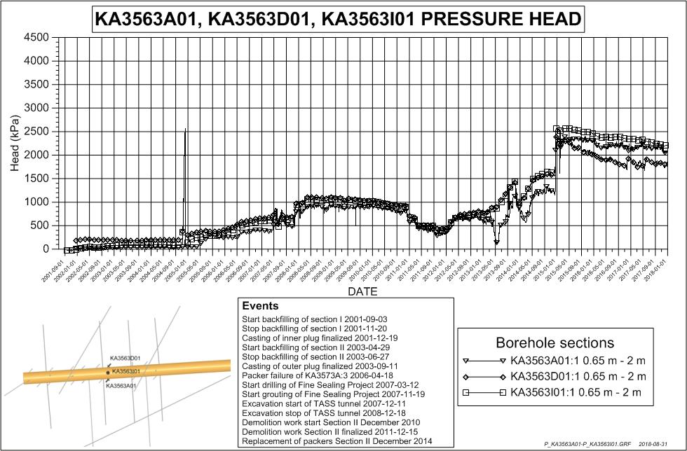
103 SKB P


104 102 SKB P-18-22

105 SKB P

106 104 SKB P-18-22

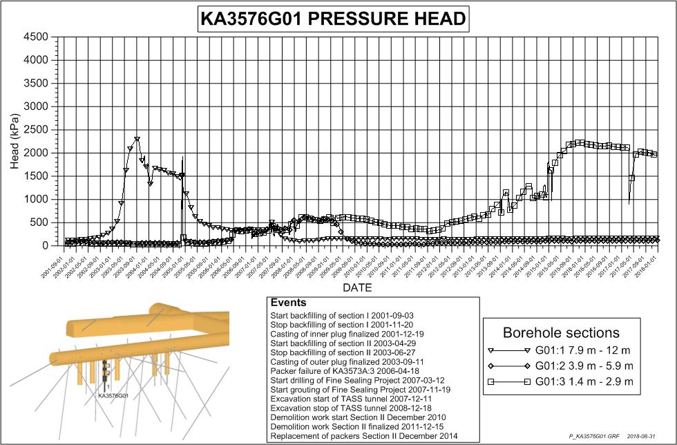
107 SKB P


108 106 SKB P-18-22

109 SKB P

110 108 SKB P-18-22

111 SKB P


112 110 SKB P-18-22

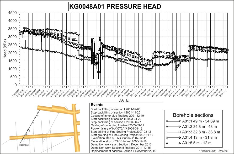
113 SKB P

114 112 SKB P-18-22

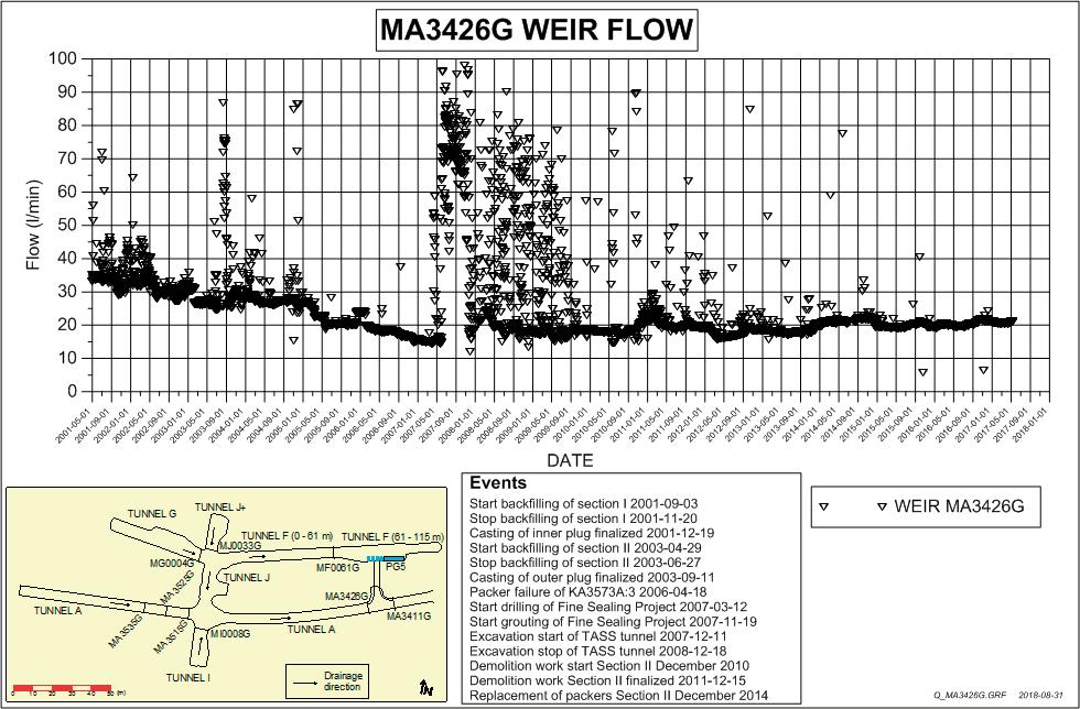
115 SKB P


116 114 SKB P-18-22

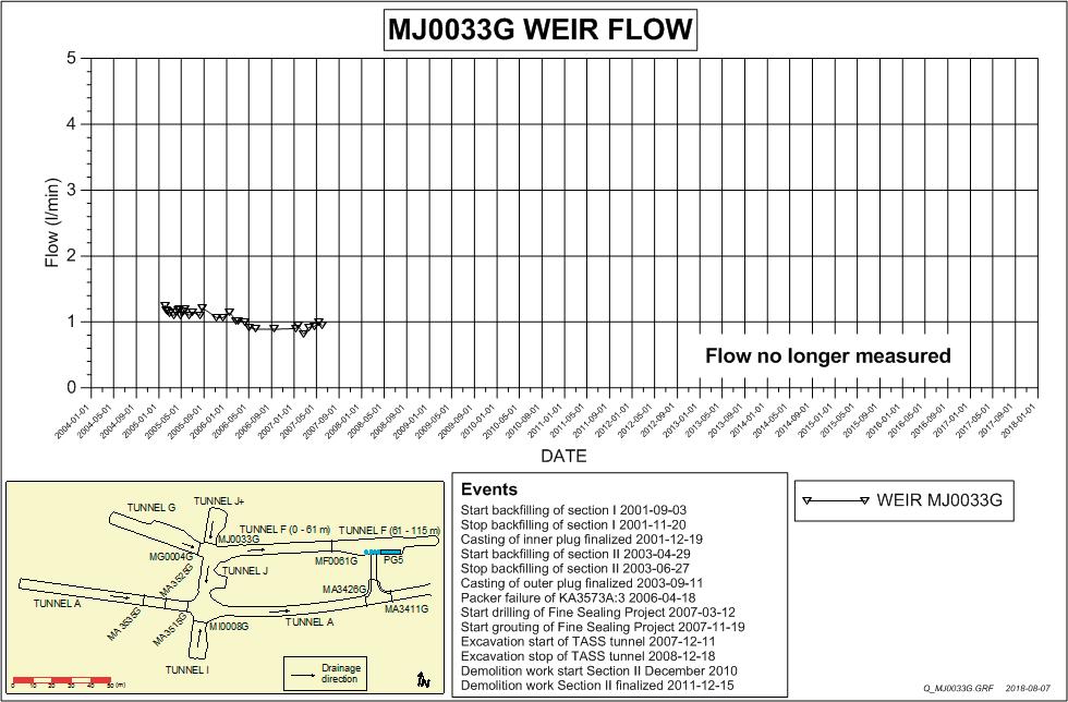
117 SKB P
118 116 SKB P-18-22

119 SKB P
Module 6: Integrals and applications
 Department of Mathematics SF65 Calculus Year 5/6 Module 6: Integrals and applications Sections 6. and 6.5 and Chapter 7 in Calculus by Adams and Essex. Three lectures, two tutorials and one seminar. Important
Boiler with heatpump / Värmepumpsberedare
 Boiler with heatpump / Värmepumpsberedare QUICK START GUIDE / SNABBSTART GUIDE More information and instruction videos on our homepage www.indol.se Mer information och instruktionsvideos på vår hemsida
Beijer Electronics AB 2000, MA00336A, 2000-12
 Demonstration driver English Svenska Beijer Electronics AB 2000, MA00336A, 2000-12 Beijer Electronics AB reserves the right to change information in this manual without prior notice. All examples in this
Support Manual HoistLocatel Electronic Locks
 Support Manual HoistLocatel Electronic Locks 1. S70, Create a Terminating Card for Cards Terminating Card 2. Select the card you want to block, look among Card No. Then click on the single arrow pointing
Windlass Control Panel v1.0.1
 SIDE-POWER Windlass Systems 86-08950 Windlass Control Panel v1.0.1 EN Installation manual Behåll denna manual ombord! S Installations manual SLEIPNER AB Kilegatan 1 452 33 Strömstad Sverige Tel: +46 525
P Äspö Hard Rock Laboratory. Ground magnetic survey at site for planned facility for calibration of borehole orientation equipment at Äspö
 P-12-10 Äspö Hard Rock Laboratory Ground magnetic survey at site for planned facility for calibration of borehole orientation equipment at Äspö Håkan Mattsson, GeoVista AB January 2012 Svensk Kärnbränslehantering
P650 - Takscreen. Installationsguide EN
 P650 - Takscreen Installationsguide 1309-150507EN V650-Tallinn Installation manual Montera främre linhjul 12 13 Placera linan över linhjulet och skruva tillbaka täcklocket på linhjulhuset (7). Öppna linhjulshuset
Viktig information för transmittrar med option /A1 Gold-Plated Diaphragm
 Viktig information för transmittrar med option /A1 Gold-Plated Diaphragm Guldplätering kan aldrig helt stoppa genomträngningen av vätgas, men den får processen att gå långsammare. En tjock guldplätering
Sammanfattning hydraulik
 Sammanfattning hydraulik Bernoullis ekvation Rörelsemängdsekvationen Energiekvation applikationer Rörströmning Friktionskoefficient, Moody s diagram Pumpsystem BERNOULLI S EQUATION 2 p V z H const. Quantity
Grafisk teknik IMCDP IMCDP IMCDP. IMCDP(filter) Sasan Gooran (HT 2006) Assumptions:
 Sasan Gooran (HT 2006) Assumptions:") IMCDP Grafisk teknik The impact of the placed dot is fed back to the original image by a filter Original Image Binary Image Sasan Gooran (HT 2006) The next dot is placed where the modified image has its
IMCDP Grafisk teknik The impact of the placed dot is fed back to the original image by a filter Original Image Binary Image Sasan Gooran (HT 2006) The next dot is placed where the modified image has its
Anvisning för Guide for
 Anvisning för Guide for PRISMA SENSOR 1 96243235zPC Montering i tak/installation in the ceiling Byte av kupa/change of diffuser 2 Installation Installation från gavel / Installation from the end Installationskabel
Uttagning för D21E och H21E
 Uttagning för D21E och H21E Anmälan till seniorelitklasserna vid O-Ringen i Kolmården 2019 är öppen fram till och med fredag 19 juli klockan 12.00. 80 deltagare per klass tas ut. En rangordningslista med
Montageanvisning Airway system 1000/1500 Assembly instruction Airway system 1000/1500
 S.Det är lämpligt att denna information överlämnas till användaren av anläggningen. GB. It is appropriate that this information is passed on to the user of the installation. D. Diese informationen sind
Bästa hälsningar, Catharina Lihnell Järnhester 0491-31323 070-467 37 31
 2006-10-27 Till: Statens Kärnkraftinspektion, SKI, 106 68 Stockholm Statens strålskyddsinstitut, SSI, 171 16 Stockholm Oskarshamns Kommun, Box 706, 572 28 Oskarshamn Östhammars kommun, Box 66, 742 21 Östhammar
Dokumentnamn Order and safety regulations for Hässleholms Kretsloppscenter. Godkänd/ansvarig Gunilla Holmberg. Kretsloppscenter
 1(5) The speed through the entire area is 30 km/h, unless otherwise indicated. Beware of crossing vehicles! Traffic signs, guardrails and exclusions shall be observed and followed. Smoking is prohibited
Schenker Privpak AB Telefon VAT Nr. SE Schenker ABs ansvarsbestämmelser, identiska med Box 905 Faxnr Säte: Borås
 Schenker Privpak AB Interface documentation for web service packageservices.asmx 2012-09-01 Version: 1.0.0 Doc. no.: I04304b Sida 2 av 7 Revision history Datum Version Sign. Kommentar 2012-09-01 1.0.0
Resultat av den utökade första planeringsövningen inför RRC september 2005
 Resultat av den utökade första planeringsövningen inför RRC-06 23 september 2005 Resultat av utökad första planeringsövning - Tillägg av ytterligare administrativa deklarationer - Variant (av case 4) med
PRESS FÄLLKONSTRUKTION FOLDING INSTRUCTIONS
 PRESS FÄLLKONSTRUKTION FOLDING INSTRUCTIONS Vänd bordet upp och ner eller ställ det på långsidan. Tryck ner vid PRESS och fäll benen samtidigt. Om benen sitter i spänn tryck benen mot kortsidan före de
Documentation SN 3102
 This document has been created by AHDS History and is based on information supplied by the depositor /////////////////////////////////////////////////////////// THE EUROPEAN STATE FINANCE DATABASE (Director:
Signatursida följer/signature page follows
 Styrelsens i Flexenclosure AB (publ) redogörelse enligt 13 kap. 6 och 14 kap. 8 aktiebolagslagen över förslaget till beslut om ökning av aktiekapitalet genom emission av aktier och emission av teckningsoptioner
2 Uppgifter. Uppgifter. Svaren börjar på sidan 35. Uppgift 1. Steg 1. Problem 1 : 2. Problem 1 : 3
 1 2 Uppgifter Uppgifter Svaren börjar på sidan 35. Uppgift 1. Steg 1 Problem 1 : 2 Problem 1 : 3 Uppgifter 3 Svarsalternativ. Answer alternative 1. a Svarsalternativ. Answer alternative 1. b Svarsalternativ.
INSTALLATION INSTRUCTIONS
 INSTALLATION - REEIVER INSTALLATION INSTRUTIONS RT0 RF WIRELESS ROOM THERMOSTAT AND REEIVER MOUNTING OF WALL MOUTING PLATE - Unscrew the screws under the - Pack contains... Installation - Receiver... Mounting
Accomodations at Anfasteröd Gårdsvik, Ljungskile
 Accomodations at Anfasteröd Gårdsvik, Ljungskile Anfasteröd Gårdsvik is a campsite and resort, located right by the sea and at the edge of the forest, south west of Ljungskile. We offer many sorts of accommodations
Aborter i Sverige 2008 januari juni
 HÄLSA OCH SJUKDOMAR 2008:9 Aborter i Sverige 2008 januari juni Preliminär sammanställning SVERIGES OFFICIELLA STATISTIK Statistik Hälsa och Sjukdomar Aborter i Sverige 2008 januari juni Preliminär sammanställning
Grafisk teknik IMCDP. Sasan Gooran (HT 2006) Assumptions:
 Assumptions:") Grafisk teknik Sasan Gooran (HT 2006) Iterative Method Controlling Dot Placement (IMCDP) Assumptions: The original continuous-tone image is scaled between 0 and 1 0 and 1 represent white and black respectively
Grafisk teknik Sasan Gooran (HT 2006) Iterative Method Controlling Dot Placement (IMCDP) Assumptions: The original continuous-tone image is scaled between 0 and 1 0 and 1 represent white and black respectively
SBF 127 Information
 2015-03-13 SBF 127 Information 2015-1 SBF 127:14 Giltighetstid Normgruppen har beslutat om en övergångstid för SBF 127:14. Den får tillämpas till och med 2016-12-31. SBF 127:15 Ändringsblad Det har framförts
Webbregistrering pa kurs och termin
 Webbregistrering pa kurs och termin 1. Du loggar in på www.kth.se via den personliga menyn Under fliken Kurser och under fliken Program finns på höger sida en länk till Studieöversiktssidan. På den sidan
KTH MMK JH TENTAMEN I HYDRAULIK OCH PNEUMATIK allmän kurs 2006-12-18 kl 09.00 13.00
 KTH MMK JH TENTAMEN I HYDRAULIK OCH PNEUMATIK allmän kurs 2006-12-18 kl 09.00 13.00 Svaren skall vara läsligt skrivna och så uppställda att lösningen går att följa. När du börjar på en ny uppgift - tag
IRAB Mottagare sida 2-5 Tele Radio AB Mottagare sida 6
 IRAB Mottagare sida -5 Tele Radio AB Mottagare sida 6 Installation of receiver type smd 700 4 RELAY FUNCTIONS / -4 VAC/DC PCB TYPE NO: LWEG 4L Rev: 95-09 Installation: Install the receivers in a protected
SVENSK STANDARD SS-ISO :2010/Amd 1:2010
 SVENSK STANDARD SS-ISO 14839-1:2010/Amd 1:2010 Fastställd/Approved: 2010-11-08 Publicerad/Published: 2010-11-30 Utgåva/Edition: 1 Språk/Language: engelska/english ICS: 01.040.17; 17.160 Vibration och stöt
Isometries of the plane
 Isometries of the plane Mikael Forsberg August 23, 2011 Abstract Här följer del av ett dokument om Tesselering som jag skrivit för en annan kurs. Denna del handlar om isometrier och innehåller bevis för
FORTA M315. Installation. 218 mm.
 1 Installation 2 1 2 1 218 mm. 1 2 4 5 6 7 8 9 2 G, G0= Max 100 m 1.5 mm² (AWG 15) X1, MX, Y, VH, VC = Max 200 m 0.5 mm² (AWG 20) Y X1 MX VH VC G1 G0 G 0 V 24 V~ IN 0-10 0-5, 2-6 60 s OP O 1 2 4 5 6 7
PRESS FÄLLKONSTRUKTION FOLDING INSTRUCTIONS
 PRESS FÄLLKONSTRUKTION FOLDING INSTRUCTIONS Vänd bordet upp och ner eller ställ det på långsidan. Tryck ner vid PRESS och fäll benen samtidigt. OBS! INGA STORA KRAFTER KRÄVS!! Om benen sitter i spänn tryck
SVENSK STANDARD SS
 Provläsningsexemplar / Preview SVENSK STANDARD Handläggande organ Fastställd Utgåva Sida Allmänna Standardiseringsgruppen, STG 1998-01-30 1 1 (13) SIS FASTSTÄLLER OCH UTGER SVENSK STANDARD SAMT SÄLJER
Grafisk teknik. Sasan Gooran (HT 2006)
") Grafisk teknik Sasan Gooran (HT 2006) Iterative Method Controlling Dot Placement (IMCDP) Assumptions: The original continuous-tone image is scaled between 0 and 1 0 and 1 represent white and black respectively
Grafisk teknik Sasan Gooran (HT 2006) Iterative Method Controlling Dot Placement (IMCDP) Assumptions: The original continuous-tone image is scaled between 0 and 1 0 and 1 represent white and black respectively
Stiftelsen Allmänna Barnhuset KARLSTADS UNIVERSITET
 Stiftelsen Allmänna Barnhuset KARLSTADS UNIVERSITET National Swedish parental studies using the same methodology have been performed in 1980, 2000, 2006 and 2011 (current study). In 1980 and 2000 the studies
GOLD SD 14-40. Med styrenhet/with control unit. Fläkt/ Fan. Utan filter/ Without filter. Fläkt/Fan. Fläkt/ Fan. Med filter/ With filter.
 GOLD SD 4-40 Med styrenhet/with control unit Skiss visar styrenhet för aggregat med inspektionssida vänster, styrenhet för aggregat med inspektionssida höger ser något annorlunda ut, men principen är lika./
Skola i Mariehäll Public School - Mariehäll. Gustaf Boström. Supervisor. Examiner
 Skola i Mariehäll Public School - Mariehäll Gustaf Boström Handledare/ Supervisor Examinator/ Examiner Carl Wärn Ibb Berglund Jesús Azpeitia Examensarbete inom arkitektur, grundnivå 15 hp Degree Project
2.1 Installation of driver using Internet Installation of driver from disk... 3
 &RQWHQW,QQHKnOO 0DQXDOÃ(QJOLVKÃ'HPRGULYHU )RUHZRUG Ã,QWURGXFWLRQ Ã,QVWDOOÃDQGÃXSGDWHÃGULYHU 2.1 Installation of driver using Internet... 3 2.2 Installation of driver from disk... 3 Ã&RQQHFWLQJÃWKHÃWHUPLQDOÃWRÃWKHÃ3/&ÃV\VWHP
The Arctic boundary layer
 The Arctic boundary layer Interactions with the surface, and clouds, as learned from observations (and some modeling) Michael Tjernström Department of Meteorology & the Bert Bolin Center for Climate Research,
LUNDS TEKNISKA HÖGSKOLA Institutionen för Elektro- och Informationsteknik
 LUNDS TEKNISKA HÖGSKOLA Institutionen för Elektro- och Informationsteknik SIGNALBEHANDLING I MULTIMEDIA, EITA50, LP4, 209 Inlämningsuppgift av 2, Assignment out of 2 Inlämningstid: Lämnas in senast kl
Förbundsutskott 32, broar och tunnlar
 Förbundsutskott 32, broar och tunnlar Utmärkelse till en framstående konstruktion inom bro- och tunnelområdet www.nvfnorden.org Stadgar i korthet: För ingenjörskonsten viktiga konstruktioner Behöver inte
Ersättning styrkort GOLD, stl 1-3, Version 1-3/ Replacement control circuit board GOLD, sizes 1-3, Version 1-3
 SPGO0867.0900 Ersättning styrkort GOLD, stl -, Version -/ Replacement control circuit board GOLD, sizes -, Version -. Allmänt När styrkortet byts ut försvinner alla injusterade värden som tex temperaturreglering,
ASSEMBLY INSTRUCTIONS SCALE SQUARE - STANDARD
 ASSEMBLY INSTRUCTIONS ALL COMPONENTS Metal profile 0 mm Gripper Ceiling attachments Screws for ceiling attachements (not included) Wires Metal profile 60 mm Metal profile 00 mm Felt - Full Felt - Half
8 < x 1 + x 2 x 3 = 1, x 1 +2x 2 + x 4 = 0, x 1 +2x 3 + x 4 = 2. x 1 2x 12 1A är inverterbar, och bestäm i så fall dess invers.
 MÄLARDALENS HÖGSKOLA Akademin för utbildning, kultur och kommunikation Avdelningen för tillämpad matematik Examinator: Erik Darpö TENTAMEN I MATEMATIK MAA150 Vektoralgebra TEN1 Datum: 9januari2015 Skrivtid:
Information technology Open Document Format for Office Applications (OpenDocument) v1.0 (ISO/IEC 26300:2006, IDT) SWEDISH STANDARDS INSTITUTE
 v1.0 (ISO/IEC 26300:2006, IDT) SWEDISH STANDARDS INSTITUTE") SVENSK STANDARD SS-ISO/IEC 26300:2008 Fastställd/Approved: 2008-06-17 Publicerad/Published: 2008-08-04 Utgåva/Edition: 1 Språk/Language: engelska/english ICS: 35.240.30 Information technology Open Document
SVENSK STANDARD SS-ISO/IEC 26300:2008 Fastställd/Approved: 2008-06-17 Publicerad/Published: 2008-08-04 Utgåva/Edition: 1 Språk/Language: engelska/english ICS: 35.240.30 Information technology Open Document
Tentamen i Matematik 2: M0030M.
 Tentamen i Matematik 2: M0030M. Datum: 203-0-5 Skrivtid: 09:00 4:00 Antal uppgifter: 2 ( 30 poäng ). Examinator: Norbert Euler Tel: 0920-492878 Tillåtna hjälpmedel: Inga Betygsgränser: 4p 9p = 3; 20p 24p
WindPRO version 2.7.448 feb 2010. SHADOW - Main Result. Calculation: inkl Halmstad SWT 2.3. Assumptions for shadow calculations. Shadow receptor-input
 SHADOW - Main Result Calculation: inkl Halmstad SWT 2.3 Assumptions for shadow calculations Maximum distance for influence Calculate only when more than 20 % of sun is covered by the blade Please look
SWESIAQ Swedish Chapter of International Society of Indoor Air Quality and Climate
 Swedish Chapter of International Society of Indoor Air Quality and Climate Aneta Wierzbicka Swedish Chapter of International Society of Indoor Air Quality and Climate Independent and non-profit Swedish
Materialplanering och styrning på grundnivå. 7,5 högskolepoäng
 Materialplanering och styrning på grundnivå Provmoment: Ladokkod: Tentamen ges för: Skriftlig tentamen TI6612 Af3-Ma, Al3, Log3,IBE3 7,5 högskolepoäng Namn: (Ifylles av student) Personnummer: (Ifylles
GOLD SD 50-80. Fläkt 2/ Fan 2. Fläkt 1/ Fan 1. Fläkt/ Fan. Utan filter/ Without filter. Fläkt 1/ Fan 1. Fläkt 2/ Fan 2. Med filter/ With filter Filter
 SE/G.ELSD5080.0803 GOLD SD 50-80 Med styrenhet/with control unit Skiss visar styrenhet för aggregat med inspektionssida vänster, styrenhet för aggregat med inspektionssida höger ser något annorlunda ut,
STORSEMINARIET 3. Amplitud. frekvens. frekvens uppgift 9.4 (cylindriskt rör)
") STORSEMINARIET 1 uppgift SS1.1 A 320 g block oscillates with an amplitude of 15 cm at the end of a spring, k =6Nm -1.Attimet = 0, the displacement x = 7.5 cm and the velocity is positive, v > 0. Write
STORSEMINARIET 1 uppgift SS1.1 A 320 g block oscillates with an amplitude of 15 cm at the end of a spring, k =6Nm -1.Attimet = 0, the displacement x = 7.5 cm and the velocity is positive, v > 0. Write
Technical description with installation and maintenance instructions
 www.euronom.se Technical description with installation and maintenance instructions VPS 300 / 500 BXU 0710-102 EXOTANK VPS 300/500 BXU Technical description Installation and maintenance instructions Installation...2
BBT057/ BBC057 BBCD057/ BBT057-NL HOLDEN COLORADO 9/2016+ HOLDEN TRAILBLAZER WD & 4WD Models
 INSTALLATION GUIDE BBT057/ BBC057 BBCD057/ BBT057-NL HOLDEN COLORADO 9/2016+ HOLDEN TRAILBLAZER 2017+ 2WD & 4WD Models Ironman 4x4 BBT/ BBC/ BBCD/BBT057-NL Bull Bars fit to a Holden Colorado 9/2016+ It
Styrteknik: Binära tal, talsystem och koder D3:1
 Styrteknik: Binära tal, talsystem och koder D3:1 Digitala kursmoment D1 Boolesk algebra D2 Grundläggande logiska funktioner D3 Binära tal, talsystem och koder Styrteknik :Binära tal, talsystem och koder
Instruction Manual. Svenska, English. Power Bank. Model: PRBN
 Instruction Manual Svenska, English Power Bank Model: PRBN Innehåll / Content Innehåll Säkerhetsföreskrifter... 4 Delar... 5 Specifikationer... 6 Miljö / Lag och säkerhet / Förbehåll... 7 Content Safety
Plain A262. För T16 (T5) lysrör. Innehåll. Monteringsanvisning. A. Instruktion för rampmontering
 lysrör. Innehåll. Monteringsanvisning. A. Instruktion för rampmontering") Plain A262 För T16 (T5) lysrör Innehåll Ramparmatur: ändmodul En stängd gavel/ en öppen gavel Plint i båda ändarna Överkopplingssladd 1 rampgavel 1 lysrörsbytare Ramparmatur: mellanmodul Plint i en ände
Plain A262 För T16 (T5) lysrör Innehåll Ramparmatur: ändmodul En stängd gavel/ en öppen gavel Plint i båda ändarna Överkopplingssladd 1 rampgavel 1 lysrörsbytare Ramparmatur: mellanmodul Plint i en ände
Webbreg öppen: 26/ /
 Webbregistrering pa kurs, period 2 HT 2015. Webbreg öppen: 26/10 2015 5/11 2015 1. Du loggar in på www.kth.se via den personliga menyn Under fliken Kurser och under fliken Program finns på höger sida en
Solar angles Solar height h, Azimuth (bearing) a
 a") AEBF1: L5 Sun and climate F5: Solar angles and climatic pre-conditions Why do we have so little sun during the winter? Architectural design regarding the outdoor climate Solar paths Solar angles Solar
AEBF1: L5 Sun and climate F5: Solar angles and climatic pre-conditions Why do we have so little sun during the winter? Architectural design regarding the outdoor climate Solar paths Solar angles Solar
Montageanvisning Airway system 1000/1500 Assembly instruction Airway system 1000/1500
 S.Det är lämpligt att denna information överlämnas till användaren av anläggningen. GB. It is appropriate that this information is passed on to the user of the installation. D. Diese informationen sind
Isolda Purchase - EDI
 Isolda Purchase - EDI Document v 1.0 1 Table of Contents Table of Contents... 2 1 Introduction... 3 1.1 What is EDI?... 4 1.2 Sending and receiving documents... 4 1.3 File format... 4 1.3.1 XML (language
1. Unpack content of zip-file to temporary folder and double click Setup
 Instruktioner Dokumentnummer/Document Number Titel/Title Sida/Page 13626-1 BM800 Data Interface - Installation Instructions 1/8 Utfärdare/Originator Godkänd av/approved by Gäller från/effective date Mats
BOENDEFORMENS BETYDELSE FÖR ASYLSÖKANDES INTEGRATION Lina Sandström
 BOENDEFORMENS BETYDELSE FÖR ASYLSÖKANDES INTEGRATION Lina Sandström Frågeställningar Kan asylprocessen förstås som en integrationsprocess? Hur fungerar i sådana fall denna process? Skiljer sig asylprocessen
MCP-16RC, Air Purification
 Kompakt patronfilter med tryckstötsrensning. MCP-16RC Air Purification Tower är ett kompakt patronfilter för decentraliserad luftrening inomhus, där luft återåtervinning är möjlig. Den kompakta filterenheten
Support for Artist Residencies
 1. Basic information 1.1. Name of the Artist-in-Residence centre 0/100 1.2. Name of the Residency Programme (if any) 0/100 1.3. Give a short description in English of the activities that the support is
säkerhetsutrustning / SAFETY EQUIPMENT
 säkerhetsutrustning / SAFETY EQUIPMENT Hastighetsvakt / Speed monitor Kellves hastighetsvakter används för att stoppa bandtransportören när dess hastighet sjunker under beräknade minimihastigheten. Kellve
Monteringsanvisning Nödutrymningsbeslag ASSA 179E
 Monteringsanvisning Nödutrymningsbeslag ASSA 179E Denna monteringsanvisning avser nödutrymningsbeslag ASSA 179E med artikelnummer 364371 i kombination med låshus Abloy EL580 med artikelnummer EL580100011.
TEXTURED EASY LOCK BLOCK INSTALLATION GUIDE. australianpaving.com.au
 TEXTURED EASY LOCK BLOCK INSTALLATION GUIDE 1800 191 131 australianpaving.com.au TEXTURED EASY LOCK BLOCK The Textured Easy Lock Block retaining wall system is the premium retaining wall product for near
Preschool Kindergarten
 Preschool Kindergarten Objectives CCSS Reading: Foundational Skills RF.K.1.D: Recognize and name all upper- and lowercase letters of the alphabet. RF.K.3.A: Demonstrate basic knowledge of one-toone letter-sound
SVENSK STANDARD SS-EN ISO 19108:2005/AC:2015
 SVENSK STANDARD SS-EN ISO 19108:2005/AC:2015 Fastställd/Approved: 2015-07-23 Publicerad/Published: 2016-05-24 Utgåva/Edition: 1 Språk/Language: engelska/english ICS: 35.240.70 Geografisk information Modell
Vätebränsle. Namn: Rasmus Rynell. Klass: TE14A. Datum: 2015-03-09
 Vätebränsle Namn: Rasmus Rynell Klass: TE14A Datum: 2015-03-09 Abstract This report is about Hydrogen as the future fuel. I chose this topic because I think that it s really interesting to look in to the
Installation Instructions
 Installation Instructions (Cat. No. 1794-IE8 Series B) This module mounts on a 1794 terminal base unit. 1. Rotate keyswitch (1) on terminal base unit (2) clockwise to position 3 as required for this type
Questionnaire for visa applicants Appendix A
 Questionnaire for visa applicants Appendix A Business Conference visit 1 Personal particulars Surname Date of birth (yr, mth, day) Given names (in full) 2 Your stay in Sweden A. Who took the initiative
E4 Sundsvall Sundsvallsbron
 E4 Sundsvall Sundsvallsbron E4 Sundsvall LEVERANTÖRSDAG EN NY VÄG. 1000 2009 NYA MÖJLIGHETER One new road. 1000 new opportunities. Ove Malmberg, Assistant Project Manager 2 2014-10-10 Project E4 Sundsvall
Undergraduate research:
 Undergraduate research: Laboratory experiments with many variables Arne Rosén 1, Magnus Karlsteen 2, Jonathan Weidow 2, Andreas Isacsson 2 and Ingvar Albinsson 1 1 Department of Physics, University of
CompactAIR Center Ventilation - Filtrering - Uppvärmning CompactAIR Center Ventilation - Filtration - Heating
 CompactAIR / CompactAIR CompactAIR Center Ventilation - Filtrering - Uppvärmning CompactAIR Center Ventilation - Filtration - Heating Typenschlüssel / Type Code Beteckning / Type code Compact AIR / CompactAIR
3 rd October 2017
 3 rd October 2017 Failures of Scaffold False work Failures Form work Bursting Trench Support Failure Hoarding Failures Can be expensive and result in fatalities and serious injuries Cardiff
Självkörande bilar. Alvin Karlsson TE14A 9/3-2015
 Självkörande bilar Alvin Karlsson TE14A 9/3-2015 Abstract This report is about driverless cars and if they would make the traffic safer in the future. Google is currently working on their driverless car
LÄNKHJUL S3. Monteringsanvisning för: Länkhjul S3
 MONTERINGSANVISNING LÄNKHJUL S3 Art.no. 8822117 Rev.2018-01 Link to english Monteringsanvisning för: Länkhjul S3 art.nr. 2002010 Länkhjul S3 90 mm art.nr. 2002020 Länkhjul S3 120 mm art.nr. 2002030 Länkhjul
Schenker Privpak AB Telefon 033-178300 VAT Nr. SE556124398001 Schenker ABs ansvarsbestämmelser, identiska med Box 905 Faxnr 033-257475 Säte: Borås
 Schenker Privpak AB Interface documentation for Parcel Search 2011-10-18 Version: 1 Doc. no.: I04306 Sida 2 av 5 Revision history Datum Version Sign. Kommentar 2011-10-18 1.0.0 PD First public version.
A study of the performance
 A study of the performance and utilization of the Swedish railway network Anders Lindfeldt Royal Institute of Technology 2011-02-03 Introduction The load on the railway network increases steadily, and
SkillGuide. Bruksanvisning. Svenska
 SkillGuide Bruksanvisning Svenska SkillGuide SkillGuide är en apparat utformad för att ge summativ återkoppling i realtid om hjärt- och lungräddning. www.laerdal.com Medföljande delar SkillGuide och bruksanvisning.
Installation manual for pool enclosure Installationsmanual för pooltak
 Installation manual for pool enclosure Installationsmanual för pooltak Assembling a module Ihopsättning av en modul Cut careful 3cm of the plastic protection folie from BOTH sides of the polycarbonate
Kursplan. EN1088 Engelsk språkdidaktik. 7,5 högskolepoäng, Grundnivå 1. English Language Learning and Teaching
 Kursplan EN1088 Engelsk språkdidaktik 7,5 högskolepoäng, Grundnivå 1 English Language Learning and Teaching 7.5 Higher Education Credits *), First Cycle Level 1 Mål Efter genomgången kurs ska studenten
Eternal Employment Financial Feasibility Study
 Eternal Employment Financial Feasibility Study 2017-08-14 Assumptions Available amount: 6 MSEK Time until first payment: 7 years Current wage: 21 600 SEK/month (corresponding to labour costs of 350 500
COPENHAGEN Environmentally Committed Accountants
 THERE ARE SO MANY REASONS FOR WORKING WITH THE ENVIRONMENT! It s obviously important that all industries do what they can to contribute to environmental efforts. The MER project provides us with a unique
GigaCom AB Säterigatan Göteborg
 *LJD'XFW DEHONDQDOV\VWHP DY*LJD&RP/7' GigaDuct kabelkanalsystem för fiberoptiskt patchkablage är speciellt konstruerat och producerat för den Europeiska marknaden. Systemet är helt slutet och därför beröringsskyddat.
Datasäkerhet och integritet
 Chapter 4 module A Networking Concepts OSI-modellen TCP/IP This module is a refresher on networking concepts, which are important in information security A Simple Home Network 2 Unshielded Twisted Pair
ISO general purpose metric screw threads Selected sizes for screws, bolts and nuts
 SVENSK STANDARD SS-ISO 262 Fastställd 2003-08-01 Utgåva 1 Metriska ISO-gängor för allmän användning Utvalda storlekar för skruvar och muttrar ISO general purpose metric screw threads Selected sizes for
Sealing of investigation boreholes
 Technical Report TR-18-18 December 2018 Sealing of investigation boreholes Full scale field test and large-scale laboratory tests Torbjörn Sandén Ulf Nilsson Lars-Erik Johannesson Patrik Hagman Göran Nilsson
The Finite Element Method, FHL064
 The Finite Element Method, FHL064 Division of Solid Mechanics Course program, vt2, 20 Course description The finite element method (FEM) is a numerical method able to solve differential equations, i.e.
Observationshotellet. The observation hotel. Fanny Vallo !!! Ersätt bilden med en egen bild. Emma Karlsson Martin Hedenström Ljung.
 Observationshotellet The observation hotel Fanny Vallo Handledare/ Supervisor B Bojan Boric Emma Karlsson Martin Hedenström Ljung Examinator/ Examiner Erik Wingquist Examensarbete inom arkitektur, grundnivå
Document ID. Version Author Lennart Börgesson/Clay Technology AB Lars-Erik Johannesson/Clay Technology AB Heikki Raiko/VTT
 Public Report Document ID Version 1.0 Status Approved 1206894 Author Lennart Börgesson/Clay Technology AB Lars-Erik Johannesson/Clay Technology AB Heikki Raiko/VTT Reviewed by Reg no Date 2009-08-27 Reviewed
Module 1: Functions, Limits, Continuity
 Department of mathematics SF1625 Calculus 1 Year 2015/2016 Module 1: Functions, Limits, Continuity This module includes Chapter P and 1 from Calculus by Adams and Essex and is taught in three lectures,
Image quality Technical/physical aspects
 (Member of IUPESM) Image quality Technical/physical aspects Nationella kvalitetsdokument för digital radiologi AG1 Michael Sandborg och Jalil Bahar Radiofysikavdelningen Linköping 2007-05-10 Requirements
Writing with context. Att skriva med sammanhang
 Writing with context Att skriva med sammanhang What makes a piece of writing easy and interesting to read? Discuss in pairs and write down one word (in English or Swedish) to express your opinion http://korta.nu/sust(answer
TN LR TT mg/l N b) 2,6-Dimethylphenole
 2,6-Dimethylphenole") TN LR TT 0.5-14 mg/l N b) 2,6-Dimethylphenole 283 Instrument specific information The test can be performed on the following devices. In addition, the required cuvette and the absorption range of the photometer
TN LR TT 0.5-14 mg/l N b) 2,6-Dimethylphenole 283 Instrument specific information The test can be performed on the following devices. In addition, the required cuvette and the absorption range of the photometer
ISO general purpose screw threads Basic profile Part 1: Metric screw threads
 SVENSK STANDARD SS-ISO 68-1 Fastställd 2003-08-01 Utgåva 1 ISO-gängor för allmän användning Basprofil Del 1: Metriska ISO-gängor ISO general purpose screw threads Basic profile Part 1: Metric screw threads