P Forsmark site investigation. Drilling of the telescopic borehole KFM02B at drill site DS2. Lars-Åke Claesson, Mirab Mineral Resurser AB
|
|
|
- Susanne Hermansson
- för 6 år sedan
- Visningar:
Transkript
1 P Forsmark site investigation Drilling of the telescopic borehole KFM02B at drill site DS2 Lars-Åke Claesson, Mirab Mineral Resurser AB Göran Nilsson, Anders Ullberg GNC AB September 2007 Svensk Kärnbränslehantering AB Swedish Nuclear Fuel and Waste Management Co Box 5864 SE Stockholm Sweden Tel Fax
2 ISSN Tänd ett lager: SKB P P, R eller TR. Forsmark site investigation Drilling of the telescopic borehole KFM02B at drill site DS2 Lars-Åke Claesson, Mirab Mineral Resurser AB Göran Nilsson, Anders Ullberg GNC AB September 2007 Keywords: AP PF , AP PF , Core drilling, Overcoring, Drill site DS2. This report concerns a study which was conducted for SKB. The conclusions and viewpoints presented in the report are those of the authors and do not Keywords: necessarily Kaka, coincide Kakmonster, with those Mupparna, of the client. Kermit. This Data report in SKB s concerns database a study can be which changed was conducted for different for reasons. SKB. The Minor conclusions changes and in SKB s viewpoints database presented will not in necessarily the report result are those in a of revised the author(s) report. Data and do revisions not necessarily may also be coincide presented with as those supplements, of the client. available at A pdf version of this document can be downloaded from
3 Abstract At drill site DS2 within the Forsmark investigation area, a 1,000 m deep telescopic borehole, KFM02A, was initially drilled during 2002, indicating low-fractured and hydraulically lowconductive rock at depth, whereas the shallow parts were fractured and to some extent highly water-yielding. In the course of the site investigations a decision was made to drill another telescopic borehole, in order to permit rock stress determinations by overcoring measurements down to repository depth. This second core drilled borehole at DS2, which is denominated KFM02B, is m long and reaches about 565 m in vertical distance from the ground surface (inclined from the horizon). The upper part was percussion drilled with mm diameter to m and was cased with a stainless steel casing after which the gap between the borehole wall and the casing was grouted. These measures entailed that all inflow of ground water to the percussion drilled part of the borehole ceased. More than 40 rock stress measurement attempts with the overcoring technique were performed between m resulting in a better knowledge of the character of the rock stress field inside the Forsmark tectonic lens. However, from the beginning of the rock stress measurement programme difficulties to achieve an efficient cleaning from drill cuttings of the so called pilot borehole, which for each measurement is drilled from the bottom of the ordinary borehole for installation of the measurement probe. This resulted in irregular gluing that often disturbed the measurement. Flushing water and drilling debris was supposed to be discharged into a highly water-yielding fracture at c. 100 m, and when pulling the drill string, the flow of suspended drill cuttings was reversed, i.e. out from the fracture and into the borehole, resulting in settlement of drill cuttings in the pilot hole. In order to seal or at least decrease the hydraulic conductivity of this fracture, a grouting attempt in section m was performed. A sampling- and measurement programme for core drilling provided preliminary information about the geological and hydraulic character of the borehole directly on-site. It also served as a basis for extended post-drilling analyses. E.g. the drill cores together with later produced video images of the borehole wall (so called BIPS-images), were used as working material for the borehole mapping (so called Boremap mapping) performed after drilling. Results of the Boremap mapping of KFM02B are presented in this report. In addition, 106 samples of drill cores for analyses of the hydrogeochemical characteristics of pore space groundwater in low permeable rock were collected, carefully packed according to a special procedure and successfully delivered to a laboratory in Bern. After completed drilling, grooves were milled into the borehole wall at certain intervals as an aid for length calibration when performing different kinds of borehole measurements after drilling. Although a better characterization of the rock stress field was achieved than previously, the activity also demonstrated some limitations of the overcoring method with dimension 76 at stress levels like those prevailing within the Forsmark candidate area due to micro-fracturing, sometimes resulting in core discing. This problem caused that the overcoring stress measurements were interrupted before repository depth (i.e. at least 400 m vertical depth) was achieved. 3
4 Sammanfattning På borrplats BP2 i Forsmarks undersökningsområde borrades redan år 2002 ett m djupt teleskopborrhål, KFM02A. Borrhålet uppvisade ett sprickfattigt och hydrauliskt sett lågkonduktivt berg mot djupet, medan de övre partierna hade förhöjd sprickfrekvens och i vissa sektioner hög vattenföring. Under platsundersökningens gång beslutades att ytter ligare ett teleskopborrhål skulle borras på denna borrplats för att möjliggöra bergspän ningsmätningar med överborrningsmetoden ner till förvarsdjup. Borrhålet, som benämns KFM02B, blev 573,87 m långt och når cirka 565 m vertikalt (är ansatt med 80,27 lutning från horisontalplanet). Den övre delen av borrhålet hammar borrades med dimension 241,6 mm till 87,10 m och kläddes in med ett rostfritt foderrör. Slutligen cementinjekterades spalten mellan borrhålsvägg och foderrör så att fullgod täthet uppnåddes. Sammanlagt utfördes ett 40-tal överborrningsmätningar i intervallet m. När bergspänningsmätningarna inleddes konstaterades emellertid stora svårigheter att uppnå fullgod limning av mätcellen i det s.k. pilotborrhålet, som borras från botten av det ordinarie kärn borrhålet vid varje mättillfälle. Problemet misstänktes bero på otillräcklig rengöring av pilotborrhålet från borrkax. Eftersom det fanns ett sprickigt parti med hög hydraulisk kon duktivitet runt 100 m fanns en misstanke om att spolvatten med suspenderat borrkax pres sades in i denna spricka för att senare, när rörsträngen drogs upp ur hålet sugas ut i borr hålet. Borrkaxet hade därefter möjlighet att sedimentera i pilotborrhålet. För att avtäta in flödena i borrhålet utfördes en injektering i intervallet m. Ett mät- och provtagningsprogram för kärnborrningen gav preliminär information om borrhålets geologiska och hydrauliska karaktär direkt under pågående borrning samt underlag för fördjupade analyser efter borrning. Bland de insamlade proverna utgör borrkärnorna tillsammans med videofilm av borrhålsväggen (s.k. BIPS-bilder), arbets materialet för den borrhålskartering (s.k. Boremapkartering) som utförs efter borrning. Även resultaten från Boremapkarteringen av KFM02B finns redovisad i föreliggande rapport. Dessutom togs 106 kärnprover som förpackades enligt en speciell procedur och skickades till ett laboratorium i Bern för analys av den kemiska sammansättningen av grundvattnet i bergmatrisens porer. Efter avslutad borrning frästes referensspår in i borrhålsväggen med syftet att användas för längdkalibrering i samband med olika typer av borrhålsmätningar som senare utförs i det färdiga borrhålet. Bergspänningsmätningarna i KFM02B förbättrade kunskaperna om spänningsfälts karaktär inom Forsmarks kandidatområde. Mätkampanjen visade emellertid också att överborr ningsmetoden i dimension 76 mm vid de spänningsnivåer som råder i Forsmarks kandi datområde har vissa begränsningar, sannolikt orsakade av mikrouppsprickning i den över borrade borrkärnan, som ibland också kan leda till s.k. ore discing. Detta var orsaken till att överborrningskampanjen avbröts innan mätningarna nått förvarsdjup, dvs minst 400 m vertikaldjup. 4
5 Contents 1 Introduction 7 2 Objective and scope 11 3 Equipment Drilling equipment Drilling equipment on KFM02B Rock stress measurement device Flushing/return water system function and equipment Groove milling equipment Equipment for deviation measurements 20 4 Execution General Preparations Execution of drilling at KFM02B Mobilization Drilling of section m Core drilling, measurements and sampling during drilling Finishing off work Data handling/post processing Nonconformities 23 5 Results Drilling progress KFM02B Geometrical and technical design of borehole KFM02B Percussion drilling KFM02B m Drilling Measurements while drilling Core drilling KFM02B m Drilling Core sampling KFM02B Rock stress measurement KFM02B Measurements while drilling KFM02B Flushing water and return water flow parameters Electric conductivity of flushing water Chemical composition of flushing water Sampling pore space groundwater in low permeable rocks Groove milling KFM02B Recovery of drill cuttings Deviation measurements in KFM02B Consumables 41 References 43 Appendix A Well cad presentation of the percussion drilled part of borehole KFM02B 45 Appendix B Well cad presentation of the entire borehole KFM02B 47 Appendix C Chemical analyses from flushing water well HFM

6 1 Introduction Site investigations are currently being performed by SKB for location and safety assessment of a deep repository for high level radioactive waste /1/. The investigations are carried out in two Swedish municipalities, Östhammar and Oskarshamn. The site investigation area in Östhammar is situated close to the Forsmark nuclear power facilities /2/ and /3/, see Figure 1-1. This document reports the results gained by core drilling of borehole KFM02B, which is one of the activities performed within the site investigation at Forsmark. The work was carried out in accordance with Activity Plan AP PF A sub-activity, sampling of drill cores specimens for analysis of the hydrogeochemical characteristics of pore space groundwater, was conducted in compliance with Activity Plan AP PF The Activity Plans and other controlling documents for performance of this activity are listed in Table 1-1. These papers are all SKB s internal controlling documents. Drilling is one important activity within the scope of the site investigations. Three main types of boreholes are produced: core drilled and percussion drilled boreholes in solid rock and short boreholes drilled through the soil layer. The last type may be accomplished by different drilling techniques, e.g. percussion drilling or auger drilling. Figure 1-1. The site investigation area at Forsmark including the candidate area selected for more detailed investigations. Drill sites DS1-12 are marked with blue dots. 7
7 Table 1 1. Controlling documents for performance of the activity. Activity Plan Number Version Teleskopborrning och bergspänningsmätningar i KFM02B. AP PF Pore space groundwater in low permeable crystalline rocks in AP PF borehole KFM02B. Method Descriptions Number Version Metodbeskrivning för kärnborrning. SKB MD Metodbeskrivning för hammarborrning. SKB MD Metodbeskrivning för genom förande av hydrauliska enhålspumptester. SKB MD Metodbeskrivning för registrering och provtagning av spolvattenparametrar SKB MD samt borrkax under kärnborrning. Method Description for in situ stress measurements by means of overcoring using the Borre probe. SKB MD Method Instructions Number Version Rengöring av borrhålsutrustning och viss markbaserad utrustning. SKB MD Användning av kemiska produkter och material vid borrning och undersökning. SKB MD The deepest boreholes drilled at the site investigation are drilled with core drilling techniques. In total, three sub-vertical and eleven inclined, approximately 800 1,000 m long, cored boreholes are drilled within the investigation area. Besides the deep holes, six semi-deep ( m) boreholes and five short ( m) boreholes have been core drilled. The boreholes are located at twelve drill sites, see Figure 1-1, where each site may include between one and four cored boreholes as well as percussion drilled holes and soil boreholes. By drilling the deep boreholes, a so called telescopic drilling technique is applied, entailing that the upper c m section of the borehole is percussion drilled with a large diameter ( 200 mm), whereas the borehole interval 100 1,000 m is core drilled with a diameter of approximately mm. Prior to drilling of KFM02B, three short or semi-deep boreholes, KFM01B (501 m), KFM07B (299 m) and KFM07C (500 m) were used for overcoring rock stress measurements. In order to carry out supplementary rock stress measurements, focusing especially at the rock volumes close to a major, gently dipping fracture zone, ZFMA2, a new borehole, KFM02B, was drilled at drill site DS2, where the 1,002 m deep telescopic borehole KFM02A had previously been sited. This borehole penetrated deformation zone ZFMA2 within the borehole section m. The new borehole at DS2, KFM02B, was drilled to m length by applying the telescopic drilling technique. The percussion drilled part to m was performed between Jan 18 th and Jan 30 th, 2006, and the core drilled part between June 6 th, 2006, and Feb 13 th, Close to the core drilled boreholes at drill site DS2, also percussion drilled boreholes in soil and solid rock have been drilled for different purposes. The lengths of these boreholes vary between a few metres to 221 m. The locations of all boreholes at drill site DS2 are displayed in Figure 1-2. Results from drilling of the flushing water well HFM05, used for the supply of flushing water when drilling KFM02A and KFM02B, and a monitoring well in hard rock, HFM04, have been reported separately /4/. Results from drilling of KFM02A were reported in /5/ and the geological mapping of borehole KFM02A (so called Boremap mapping) in /6/. The overcoring measurements in borehole KFM02B will be displayed in /7/, whereas the Boremap mapping of KFM02B is presented in /8/. 8
 and two monitoring wells in soil (SFM0004-05).")
8 Figure 1-2. Borehole locations at drill site DS2. Besides the telescopic boreholes KFM02A and KFM02B, the drill site includes two monitoring wells in solid rock (HFM04 and HFM05) and two monitoring wells in soil (SFM ). HFM05 was also used as a water well supplying flushing water when drilling KFM02A and KFM02B. The projection of inclined boreholes on the horizontal plane at top of casing is shown in the figure. Original data from the reported activities are stored in the primary database Sicada. Data are traceable in Sicada by the Activity Plan number (AP PF for drilling of KFM02B and AP PF for pore space water sampling and analysis). Only data in databases are accepted for further interpretation and modelling. The data presented in this report are regarded as copies of the original data. Data in the databases may be revised, if needed. Such revisions will not necessarily result in a revision of the P-report, although the normal procedure is that major revisions entail a revision of the P-report. Minor revisions are normally presented as supplements, available at 9
9 2 Objective and scope The main objectives of drilling deep telescopic boreholes at the site investigation are the following: To provide rock samples from the ground surface to the borehole bottom. Percussion drilling through the overburden produces soil samples recovered to the surface by compressed air. These samples are collected with a frequency of one sample per metre. The same sampling frequency is applied for the drill cuttings produced when percussion drilling the upper c m of the solid rock. Below, the core drilling provides (in principle) continuous drill cores down to the borehole bottom. The rock samples collected during drilling are used for lithological, structural and rock mechanical characterization as well as for determination of transport properties of the bedrock from the rock surface to the full drilling depth. To render geophysical borehole investigations possible, e.g. TV logging, borehole radar logging and conventional geophysical logging as an aid for the geological/rock mechanical characterization. To allow hydraulic borehole tests (single-hole tests as well as interference tests) for characterization of the hydrogeological conditions. As regards KFM02B an interference test combined with a tracer test was performed between the two adjacent boreholes KFM02A and KFM02B. To make water sampling possible down to and below repository depth. High-class hydrogeochemical sampling/analysis demands special measures during and after drilling in order to keep the borehole clean. When these measures have been taken, the borehole is categorized as a borehole of chemical type. Only boreholes of this category are approved for advanced hydrogeochemical and microbiological characterization. To enable long-term hydraulic and hydrogeochemical monitoring at different levels of the bedrock. All objectives mentioned above apply to borehole KFM02B, although the hydrogeo chemical investigations in this borehole addressed only pore space water in low-conductive rock and not groundwater from water-yielding fractures, which is a more common type of investigations. Another specific objective for borehole KFM2B was to conduct rock stress measurements during drilling by applying the overcoring technique. A key issue was to characterize the stress field and its dependence on the major gently dipping fracture zone ZFMA2. During drilling, a number of drilling related parameters are monitored by a drilling monitoring system. Part of these data sets, in this report called DMS (Drilling Monitoring System) data, which after drilling are transferred to Sicada, may be used as supplementary data for geological and hydraulic characterization as well as for assessment of technical aspects of the drilling operations. DMS-data are described in this report. 11

10 3 Equipment A Puntell MX 1000 percussion drill rig, see Figure 3-1, was engaged for the upper part of drilling borehole KFM02B while the core drilled part was made with an Onram 2000 CCD from Hagby and a B20 core drilling system from Atlas Copco. A short presentation of the drilling equipments is provided below. 3.1 Drilling equipment Drilling equipment on KFM02B The drilling process was first operated by a percussion drilling machine of Puntell MX 1000 type and continued with an Onram 2000 CCD core drilling system from Hagby. Due to malfunction this equipment was from m drilling length exchanged, and the remaining part of the borehole was drilled with a B20 core drilling system from Atlas Copco. The Puntell percussion drilling system is supplied with separate engines for transportation and power supplies. Water and drill cuttings are retrieved from the boreholes by a 27 bars air-compressor, type Atlas-Copco XRVS 466 Md. Technical specifications of the core drilling machines with fittings are given in Table 3-1. Core drilling with a wireline system entails recovery of the core barrel via the drilling pipe string, inside which it is hoisted up with the wireline winch. During drilling of boreholes KFM02B, a 3 m triple tube core barrel was used. The nominal core diameter for the 75.8 mm part of the borehole is 50.2 mm. Minor deviations from this diameter may however occur. Figure 3 1. The Puntell percussion drilling machine in operation on borehole KFM02B. 13
11 Table 3 1. Technical specifications of the Onram 2000 CCD and the B20 core drilling systems with appurtenances. Unit Manufacturer/type Specifications Remarks Onram 2000 Hagby-Asahi Capacity for mm holes maximum approx ,500 m depending on choice of drill string Flush water pump Bean Max flow rate: 170 L/min Max pressure: 103 bars Submersible pump Grundfos SQ Max flow rate: 200 L/min Mobile electrical plant P250HE with diesel engine Perkins GCD KVA, 200 kw, 360 A Only as reserve as the equipment is served by permanent power Compressor Atlas Copco GA75P-13 Max pressure: 12 bars Electrically supplied Flow: > 5 L/sec CCD-system Dunfoss Standard system modified for core drilling by the manufacturer B20 Atlas Copco Craelius Capacity for mm holes maximum approx. 1,500 m Flush water pump Trido 140 Max flow rate: 140 L/min Max pressure: 70 bars Submersible pump Grundfos SQ Max flow rate: 200 L/min Mobile electrical plant Atlas Copco QAS 300 GD engined with Volvo TAF 1032 TAD 300 KVA Only as reserve as the equipment is served by permanent power Compressor Atlas Copco GA75P-13 Max pressure: 13 bars Electrically supplied Flow rate 169 L/sec at 12.5 bars CCD-system Atlas Copco Standard system modified for core drilling by the manufacturer Rock stress measurement device Three-dimensional Borre probe (Figure 3-2) equipment where used for the rock stress measurements in KFM02B Flushing/return water system function and equipment Core drilling involves pumping of flushing water down the drill string, through the drill bit and out into the borehole in order 1) to conduct frictional heat away from the drill bit, and 2) to enhance the recovery of drill cuttings to the ground surface. The cuttings, suspended in the flushing water (in general mixed with groundwater), are forced from the borehole bottom to the ground surface via the gap between the borehole wall and the drilling pipes. A schematic illustration of the flushing/return water system when drilling KFM02B at DS2 is shown in Figure 3-3. Below, the following equipment systems and their functions are briefly described: equipment for preparing the flushing water, equipment for measuring flushing water parameters (flow rate, pressure, electrical conductivity and dissolved oxygen), equipment for air-lift pumping while drilling, equipment for storage and discharge of return water. 14


12 Figure 3-2. The logger unit, part of the Borre probe, is released from data to the portable computer. Drillrig Flush water tank Measurement station Elcond. Flow meter Containers Recipient HFM05 KFM02B UV EC Outlet for the oxygen measurement Nitrogen KFM02A Figure 3 3. Schematic illustration of the flushing/return water system when drilling KFM02B at DS2. For measurements of the accumulated return water volume, a mechanical water gauge was used. Preparing the flushing water The water well used for the supply of flushing water for core drilling of KFM02B was a percussion drilled well in hard rock, HFM05 (see Figure 1-2), situated approximately 125 m from the drill site. The water quality from the HFM05 well had been analysed in advance and considered as sufficiently good to serve as flushing water for KFM11A. Besides these basic demands on the flushing water quality, which were fulfilled when drilling KFM02B, the flushing water was also prepared in three steps before use, in accordance with SKB MD (Method Description for core drilling). 15
13 1) Incoming water from the water well was pumped into the flush water tank (see Figure 3-3). 2) Nitrogen was bubbled through the water in the tank in order to expel oxygen which might be dissolved in the water (see Figure 3-3). Expelled oxygen was discharged through a pressure reducing valve. Oxygen must be avoided in the flushing water because it is a critical parameter in the programme for hydrogeochemical characterization of the groundwater. The water was then kept continuously under a positive nitrogen pressure (about 1 bar) until pumped down into the borehole. 3) The incoming water from the tank was exposed to UV-radiation (inside the measurement station) before entering the trace dosing equipment, illustrated in Figure 3-3. The microbe content in the water was thereby radically reduced. 4) An organic tracer dye, Uranine, was added by the tracer dosing feeder at a concentration of 0.2 mg/l, before the water was pumped into the borehole, see Figure 3-3. Labelling the flushing water with the tracer aims at enabling detection of the flushing water content in groundwater samples collected in the borehole during or after drilling. Measurement of flushing water parameters The total quantity of water supplied to the borehole was acquired by counting the number of filled water tanks used, multiplied by the tank volume. The following flushing water parameters were measured on-line when pumping the flushing water into the borehole: flow rate, pressure, electrical conductivity, dissolved oxygen. Data were stored in a drilling monitoring system, see Section Technical specifications of the measurement instruments are presented in Table 3-2. The total quantity of water supplied to the borehole, used as a double-check of the flow measurements, was acquired by manual reading of flow meters and a conductivity meter. The readings were stored and then afterwards compared to the automatic readings, which served as data quality check. Table 3 2. Technical specifications of instruments used for measurement of flushing water parameters. Instrument Manufactorer/type Range of measurement Remarks Flow meter Krohne IFC 010-D L/min Inductive Electrical conductivity Kemotron ms/cm 200 ms/cm 0.1 ms/m 20 S/m Oxygen Orbisphere model
14 Air-lift pumping while drilling Air-lift pumping during drilling of telescopic boreholes involves pumping of compressed air into the percussion drilled portion of the borehole, forcing it to emerge at a depth of about m, depending on the depth of the percussion drilled borehole section. As the air expands in rising out of the borehole, it lifts the water up, thereby producing the air-lift pumping effect. The resulting pressure drop entails transport of much of the mixture of water and drill cuttings from the bottom of the hole up to the surface, see Figure 3-4. The resulting return water is a mixture of flushing water, groundwater from fracture zones in the rock and drill cuttings. Some of the flushing water and drill cuttings will, however, be forced into the local fracture systems, and a minor part will be left in the borehole. The air-lift pumping is continued throughout the drilling period. The air-lift pumping equipment in KFM02B consisted of several main components, see Table 3-3 and Figure 3-4. Core drilling beneath the large-diameter percussion drilled part of the borehole demands installation of a support casing, in order to avoid vibrations of the drill pipe string. This is accomplished by an inner support casing, which is further stabilized by an outer support casing supplied with steel wings resting against the borehole wall, see Figure 3-4. When installing the outer support casing, it was lowered into the borehole together with the hoses for air-lift pumping with a mobile crane. The ejector tube was fit to the outer support casing, about 200 mm above the bottom of the telescopic borehole. A 22 mm supply hose and a 40 mm return hose were connected to the ejector tube as shown in Figure 3-5. With this construction, the air leaving the ejector hose, reducing the pressure in the lower part of the ejector tube, thereby helping to lift drill cuttings from the bottom of the hole. Storage and discharge of return water At the surface level, the return hose was connected to a return pipe between the discharge head and the first return water container. The return water was discharged from the borehole via an expansion vessel and a flow meter to two containers, in which the drill cuttings separated out in the sedimentation container. Since the return water had an increased salt content, it could not, for environmental reasons, be discharged into any fresh water recipient, but had to be pumped from the container via a 1 km long pipe string to the Baltic Sea. Table 3 3. Air-lift pumping equipment used in KFM02B. Components Air compressor, 12 bars/10 m³/min Electrical supply cubicle, at least 16 A Outer support casing, 98/89 mm diameter Inner support casing, 84/77 mm diameter 2 Ejector pumps, each contained;* PEX hose, 1 22 mm PEM hose, 1 40 mm Air nozzle PEX hose, 1 22 mm Expansion vessel (= discharge head) PEM hose: 20 bars, 32 mm diameter (pressure transducer) Pressure sensor, 10 bars, instrumentation and data logging unit KFM02B X X 88 m 89 m ** m ** m ** m X 90 m X * Two mammoth pumps are always installed in each telescopic bore hole. ** Extended hose; PEX connected to air compressor and PEM connected to Cyclone. 17
15 Compressed air in Water in Water out Water and drill cuttings out ~ 10 m Outer support casing Inner support casing Air out Air in ~ m Lower pressure Higher pressure ~ 2 m Down to the borehole bottom Figure 3 4. Air-lift pumping during core drilling of a telescopic borehole. Schematic representation, where the drilling depths are only approximate. The air and instrumentation hoses are secured to the outer support casing. The compressed air raises the flushing water and drill cuttings from the hole. Return water flows between the borehole wall and the drill pipe string and then through holes in the support casing before being transported up to the surface Groove milling equipment After completion of drilling, borehole KFM02B have been used and will further be used for a variety of borehole measurements, employing many types of borehole instruments with different stretching characteristics (pipe strings, wires, cables etc). In order to provide a system for length calibration in the borehole, reference grooves have been milled into the borehole wall with a specially designed tool at regular levels, see Figure 3-6. This was carried out after drilling, but with use of the drilling machine and drill pipe string. At each level where milling was performed, two 20 mm wide grooves were milled with a distance of 10 cm between them. After milling, the reference grooves were detected with the SKB level indicator (a calliper). A BIPS-survey provided the final confirmation that the grooves exist. 18


 approx.")
16 Outer support casing Tubes are strongly anchored along the outer support casing 3 m 0.5 m Compressed air in Return water out Airlift pumping nozzle ~ 100 m Ejector Figure 3 5. Schematic representation of connection and installation of air-lift pumping nozzle and ejector on the outer protective casing. approx. 5 mm approx. 20 mm (reference groove) approx. 100 mm Figure 3-6. Layout and design of reference grooves. 19
17 3.1.5 Equipment for deviation measurements After completion of drilling, a deviation measurement was carried out with a Reflex Maxibor system, which is an optical, i.e. non-magnetic measurement system. Azimuth and dip are measured at every third metre. The collaring point coordinates and the measured values are used for calculating the coordinates of the position of the borehole at every measurement point. Also another method, based on magnetic accelerometer technique, was applied for deviation measurements in order to check the validity of the Maxibor -measurements. The surveying instrument used was the Flexit Smart Tool System. At the time of drilling KFM02B, the Maxibor -method was assessed as the most reliable of different deviation methods tested by SKB, and Maxibor-data stored in the database Sicada were normally assigned as the only deviation data set permitted to be used (so called in use displayed data ) even if another or several deviation methods had been applied in a borehole as well. However, in connection with a major quality revision regarding orientation of all identified geological objects (fractures, fracture zones rock contacts etc) conducted by SKB during late autumn 2006 to winter/early spring 2007, a reassessment of the reliability of deviation measurement methods was made, whereby the Flexit-method was judged as providing the most reliable results. Therefore a revision was made also for borehole KFM02B, and today Flexit-data provide the in use displayed deviation data set. However, all available deviation measurements, i.e. for borehole KFM02B Flexit- as well as Maxibor-data have been used for estimation of the uncertainty of deviation data. Results from the deviation measurements stored in Sicada are presented in Section
18 4 Execution 4.1 General The activity drilling of and performance of overcoring rock stress measurements in KFM02B was conducted in compliance with Activity Plan AP PF , referring to SKB MD (Method Description for core drilling). The drilling operations included the following parts: preparations, mobilisation, including lining up the machine and measuring the position, drilling, measurements, over-coring and sampling during drilling, finishing off field work, data handling. The items are presented more in detail in Sections Preparations The preparations included the contractor s service and function control of his equipment. The machinery was supplied with fuel, oil and grease entirely of the types stated in SKB MD , see Table 1-1. Finally, the equipment was cleaned in accordance with SKB MD Table Execution of drilling at KFM02B Mobilization Mobilization onto and at the site included preparation of the drill site, transport of drilling equipment, flushing water equipment, sampling boxes for drill cores, as well as hand tools etc. Furthermore, the mobilization consisted of cleaning of all in-the-hole equipment at level one in accordance with SKB MD , lining up the machine and final function control of all equipment Drilling of section m Drilling started with the Puntell machine with NO-X 280 down to 3.23 m followed by drilling to m with diameter mm and reaming to m with mm and cement grouting of the gap between the casing and the borehole wall. The soil depth was approximately 0.84 m Core drilling, measurements and sampling during drilling By core drilling of borehole KFM02B, two borehole dimensions were applied. section m was drilled with a borehole diameter of 75.8 mm after which the section was reamed to 86 mm. Drilling continued with 75.8 mm in section m with the Onram 2000 rig and after exchange to the Atlas Copco B20 machine the borehole was completed to m with a diameter of 75.8 mm. 21
19 Core drilling is associated with a programme for sampling, measurements and other activities during and immediately after drilling, cf. SKB MD However, for different reasons, during drilling of KFM02B some deviations from this programme could not be avoided. The major discrepancy compared to SKB MD was the overcoring rock stress measurements during drilling. In order to elucidate the nonconformities, the programme according to the Method Description is presented in Section 4.6, Table 4-1, together with the actual performance when drilling KFM02B. A special programme for sampling drill cores to determine pore space groundwater in low permeable crystalline rocks in the borehole was included in the activities during the drilling. It was however conducted in compliance with Activity Plan AP PF Results will be reported separately in /12/. Results from the measurements and registrations during core drilling are presented in Chapter Finishing off work The concluding work included the following items: 1) The borehole was flushed for about 10 hours in order to clean it from drilling debris adhered to the borehole walls, settled at the bottom of the hole or suspended in the water. 2) The drill string was pulled. 3) The borehole was secured with a lockable stainless steel flange. 4) The core drilling equipment was removed, the site cleaned and a joint inspection made by SKB and the contractor. 4.5 Data handling/post processing Minutes for several items with the following headlines: Activities, Cleaning of the equipment, Drilling, Borehole, Core drilling penetration rate, Deliverance of field material and Discrepancy report were filled in by the field crew, and collected by the Activity Leader, who made a control of the information and had it stored in the SKB database Sicada and are traceable by the Activity Plan number. 22
20 4.6 Nonconformities Nitrogen air flushing was performed in order to improve cleaning of the borehole from drilling debris. The core drilling operation resulted in a number of nonconformities with the Method Description. These are presented in Table 4-1 below. Table 4-1. Programme for sampling, measurements, registrations and other activities during and immediately after core drilling according to SKB MD AP PF , and the actual performance during drilling of borehole KFM02B. Activity Performance and frequency according to SKB MD and, for the last item, AP PF Performance and frequency during drilling of KFM02B Registration of drilling- and flushing water parameters. Core sampling. Deviation measurements. Hydraulic tests. Water sampling. Absolute pressure measurements. Groove milling in the borehole wall, normally at each 50 m. Over-coring rock stress measurements. Registration during the entire drilling. Continuous sampling of the entire drilled section. Normally performed every 100 m and after completion of drilling. Normally performed every 100 m, and also when penetrating larger conductive fractures/ zones. The tightness of the drilling pipe string should be controlled before each test. Normally performed every 100 m, and also when penetrating larger conductive fractures/ zones. The tightness of the drilling pipe string should be controlled before each test. Normally during natural pauses in drilling. Normally performed after completion of drilling. According to programme. According to programme. One Maxibor measurement after 243 m and two measurements after completion of drilling and two measurements with Flexit. No measurements performed. No measurements performed. No measurements performed. Nine (double) grooves performed. Measurements at 4 different levels. Performed at m, m, m and m. 23
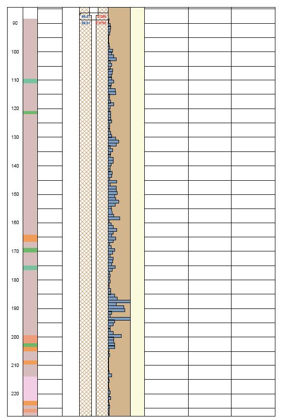
21 5 Results All data were stored in the Sicada database. An overview of the drilling progress of borehole KFM02B is given in Section 5.1, whereas geometrical data and technical design are presented in Section 5.2. Results from drilling and measurements during drilling are accounted for in: Section 5.3 (drilling m). Section 5.4 (drilling m). Section 5.5 (measurements while drilling and sampling of pore space groundwater in low permeable rock). Well Cad-presentations of borehole KFM02B are shown in: Appendix A (percussion drilled part of KFM02B). Appendix B (entire borehole KFM02B). The Well Cad plots are composite diagrams presenting the most important technical and geoscientific results from drilling and investigations made during and immediately after drilling. 5.1 Drilling progress KFM02B Borehole KFM02B was drilled during a period of slightly more than 7.5 months including summer holidays, see Figure 5-1. The prolonged drilling period was mainly due to the much time consuming overcoring rock stress measurements, but partly also to the drilling performance with only one shift/day, seven days a week. At the end of the pore space water sampling period, the drilling machine could only work 4 days a week, due to that the remote analysis laboratory kept closed during week ends. It should also be mentioned that numerous problems occurred with the rock stress measurements, among others gluing problems (the measurement probe is glued towards the wall of the pilot borehole), technical problems with the Borre probe (see Section 3.1.2), discing of the pilot drill core etc. Due to this kind of difficulties, many measurement attempts at each level were unsuccessful. KFM02B Drilling owerview Jan. Feb. June August September October Nowember October December January February w03 w04 w05 w23 w24 w25 w26 w31 w32 w33 w34 w35 w36 w37 w38 w39 w40 w41 w42 w43 w44 w45 w46 w47 w48 w49 w50 w51 w02 w03 w04 w05 w06 w07 Rock stress measurenents Percussion drilling Core drilling Atlas Copco B20 Rock pore space sampling Core drilling Onram 2000 CCD Rock pore space sampling NaI samples Figure 5-1. Overview of the drilling performance of borehole KFM02B. 25
22 5.2 Geometrical and technical design of borehole KFM02B Administrative, geometric and technical data for the core drilled borehole KFM02B are presented in Table 5-1. The technical design of the borehole is illustrated in Figures 5-2. Table 5-1. Administrative, geometric and technical data for borehole KFM02B. Parameter Borehole name Location KFM02B Drill start date Jan 18 th, 2006 Completion date Feb 13 th, 2007 Forsmark, Östhammar municipality, Sweden Drilling period to ( m) to ( m) Contractor core drilling Drillcon Core AB Percussion drill rig Puntell MX 1000 Core drill rig Onram 2000 CCD ( m) Atlas Copco B20 ( m) Position KFM02B at top of casing N (RT gon V 0: 15 / RHB 70) E Z 7.62 (m.a.s.l.) Bearing (0 360 ): Inclination (0 90 ): Position KFM02B at bottom of hole N (RT gon V 0: 15 / RHB 70) E Z (m.a.s.l.) Bearing (0 360 ): Inclination (0 90 ): Borehole length m Borehole diameter and length From 0.15 m to 3.23 m: 339 mm From 3.23 m to m: mm From to m: mm From m to m: 86.0 mm From m to m: 75.8 mm Casing diameter and length o / i = mm/319.7 mm 0.15 m to 3.15 m o / i = 339 mm/281 mm 3.15 m to 3.23 m o / i = 208 mm/200 mm 0 m to m o / i = 210 mm/200 mm m to m o / i = 208 mm/170 mm to m Transition cone inner diameter At m: m At m: m Drill core dimension m/ 50.2 mm Core interval m 26
23 3.23 m m m Technical data Borehole KFM02B Reference point Reference level 0.00 m Øo/Øi = 323.9/309.7 mm Ø (borehole) = 339 mm Soil cover 0.84 m Gap injection (cement) m m Øo/Øi = 208.0/200.0 mm down to m m m m m Ø (borehole) = mm Øo/Øi = 210.0/200.0 mm from down to m Øo/Øi = 208.0/170.0 mm Ø (borehole) = mm Ø (borehole) = 86.0 mm Reference marks (m): m Ø (borehole) = 75.8 mm Drilling reference point Northing: Easting: Elevation: Orientation Bearing (degrees): Inclination (degrees): Borehole Length: (m), RT90 2,5 gon V 0: (m), RT90 2,5 gon V 0: (m), RHB o o m Percussion drilling period Drilling start date: Drilling stop date: Core drilling period Drilling start date: Drilling stop date: Figure 5-2. Technical data of borehole KFM02B. 27
24 5.3 Percussion drilling KFM02B m Drilling Drilling of the section m was progressing between Jan 18 th, 2006, and Jan 30 th, 2006, and is the logistics for the drilling operations is presented in Figure 5-3. As mentioned in Section 4.3.2, the upper part to 3.23 m of the borehole was drilled and cased according to NO-X 280. During pilot drilling to m, an unstable section with increased fracturing and a water inflow of 140 L/min was encountered at 81 m length. The fracturing in the percussion drilled part of KFM02B, is also in line with the results from the nearby borehole KFM02A. The borehole was therefore, after reaming to mm, cased with an 200/208 mm stainless steel casing to m and a reinforced casing between m. Finally, the gap between the casing and the borehole wall was cement grouted, so that the water inflow ceased completely Measurements while drilling During, and immediately after drilling, a program for sampling and measurements was applied, cf. Section Some of the results are displayed in the Well Cad-presentation in Appendix A (deviation measurements, penetration rate and rock type distribution), whereas other results (flow data and electrical conductivity) are used only as supporting data for on-site decisions m 80 m Inflow 140 L/min Inflow 120 L/min Pilot drilling Ø mm to m KFM02B Reaming Ø mm Mammoth pumping Casing Ø 200x5 mm m Gap injection QC check Finished 70 m 60 m Casing Ø 200x4 mm m 50 m 40 m 30 m 20 m 10 m 0 m NO-X 280 casing Ø mm to 3.23 m Date Figure 5-3. Percussion drilling progress (depth and activity versus calendar time). Inflow in the figure refers to accumulated groundwater inflow. 28
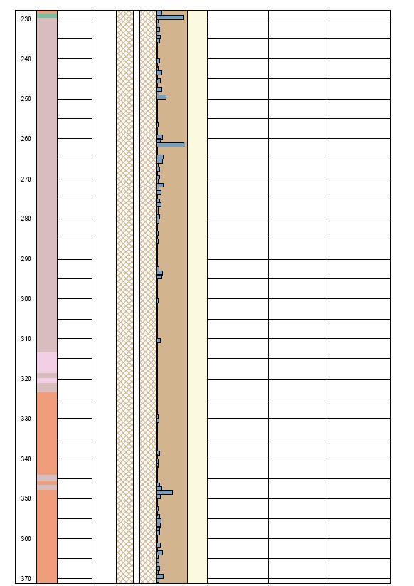
25 M Tu W Th F Sa Su M Tu W Th F Sa Su M Tu W Th F Sa Su M Tu W Th F Sa Su M Tu W Th F Sa Su M Tu W Th F Sa Su M Tu W Th F Sa Su M Tu W Th F Sa Su M Tu W Th F Sa Su M Tu W Th F Sa Su M Tu W Th F Sa Su M Tu W Th F Sa Su M Tu W Th F Sa Su M Tu W Th F Sa Su M Tu W Th F Sa Su M Tu W Th F Sa Su M Tu W Th F Sa Su M Tu W Th F Sa Su M Tu W Th F Sa Su M Tu W Th F Sa Su M Tu W Th F Sa Su M Tu W Th F Sa Su M Tu W Th F Sa Su M Tu W Th F Sa Su M Tu W Th F Sa Su M Tu W Th F Sa Su M Tu W Th F Sa Su M Tu W Th F Sa Su M Tu W Th F Sa 5.4 Core drilling KFM02B m Drilling After the percussion drilling, a break followed until the drilling of section m was performed in between June 6 th and February 13 th, 2007, (Figure 5-4). The results from drilling of KFM02B concerning lithological distribution as well as fracture frequency and characteristics were almost exactly in accordance with the results from the nearby KFM02A (the two boreholes are at the surface situated only c. 8 m from each other). Several water-yielding gently dipping fracture zones were encountered in both boreholes down to c. 510 m drilling length. The overcoring stress measurements commenced at level one ( m), but were soon interrupted when the drilling rig had to be exchanged for technical reasons, cf. Section A major water inflow at c. 100 m drilling length was encountered. At this level, due to fractured rock, also several breaks of the pilot drill cores occurred, indicating unfavourable conditions for overcoring measurements. Arguments were brought up for cement grouting of the fractured section, which was a trap for drilling debris. When pulling the drill string drill cuttings were flowing back into the borehole and settled in the pilot hole. discharged into to decrease the inflow and after permission from the Security Assessments, 500 kg Lafarge cement, was pumped into the section between m. After the cement had settled, the borehole was drilled again where after the stress measurements continued at additional three more levels, down to 307 m drilling length. 500 m 400 m M Tu W Th F Sa Su M Tu W Th F Sa Su M Tu W Th F Sa Su M Tu W Th F Sa Su M Tu W Th F Sa Su M Tu W Th F Sa Su M Tu W Th F Sa Su M Tu W Th F Sa Su M Tu W Th F Sa Su M Tu W Th F Sa Su M Tu W Th F Sa Su M Tu W Th F Sa Su M Tu W Th F Sa Su M Tu W Th F Sa Su M Tu W Th F Sa Su M Tu W Th F Sa Su M Tu W Th F Sa Su M Tu W Th F Sa Su M Tu W Th F Sa Su M Tu W Th F Sa Su M Tu W Th F Sa Su M Tu W Th F Sa Su M Tu W Th F Sa Su M Tu W Th F Sa Su M Tu W Th F Sa Su M Tu W Th F Sa Su M Tu W Th F Sa Su M Tu W Th F Sa Su M Tu W Th F Sa Tot Pore space ground water sampling Groove milling Deviation measurement with Maxibor Deviation measurement with Flexit WL Drilling progress, Onram 2000 CCD WL Drilling progress, Atlas Copco B20 Cement grouting KFM02B al 300 m Level 4 Rock pore space sampling Level m 82 samples 200 m Number of Rock stress measurements: 100 m Level 1 Level 1 Level 2 Level 1 Level 2 Level 3 Overcoring Rock Stress measurements 18 measurements 8 measurements 21 measurements Sodium Iodide NaI samples samples l m 8 samples Change of drill rig to AC B20 Level 4 8 measurements 0 m Date W636 W638 W645 W637 W639 W640 W646 W647 W625 W626 W631 W632 W648 W649 W650 W651 W624 W633 W634 W635 W702 W641 W642 W643 W644 W703 W704 W705 W706 Figure 5-4. Core drilling progress KFM02B (length versus calendar time). The diagram is also showing the logistics for the overcoring rock stress measurements and the rock pore space groundwater sampling, sodium iodide test sampling (see text below), groove milling and deviation measurements. 29
26 As for borehole KFM07C a newly developed equipment for nitrogen flushing was used, where the end of the hose was outfitted with a nozzle, designed to fit into the pilot borehole. The relatively large water inflow into the gently dipping fracture zones made it possible to flush the borehole frequently, and a clean pilot borehole was a prerequisite for effective gluing of the Borre probe used for overcoring rock stress measurements. When the rock stress measurement had been finished, the frequency of pore space groundwater sampling was increased. Towards the end of drilling, the flushing water was labelled with a new tracer, sodium iodide (NaI). Normally the flushing water is labelled with the tracer Uranine to a concentration of 0.2 mg/l, but this concentration is too low to permit analyses of the amount of flushing water in the pore space groundwater. Therefore a much higher concentration of sodium iodine, 1.0 g/l, was introduced,. However, the first attempt of adding the highly concentrated NaI into the flushing water failed, but when the equipment was modified it finally succeeded. Drilling was completed at m drilling length in early February, Core sampling KFM02B A preliminary on-site core logging was performed continuously Rock stress measurement KFM02B During the period June 15th, 2006, to December 13 th, 2006, overcoring rock stress measurements were conducted in the near vertical borehole KFM02B, with the three-dimensional Borre probe. Measurements were attempted at four levels in the borehole, m, m, m and m. From the beginning of the core drilling continuous problems with the technical performance of the Onram 2000 drilling machine caused much time delay. The problems culminated when the steering system, completely unexpectedly, dropped the drill string in the borehole. Unfortunately, the Borre probe was mounted at the bottom of the string, and when it smashed into the borehole bottom, the probe was completely destroyed, including loss of collected data. Even after service and maintenance, the Contractor could not guarantee the reliability of the steering system of the Onram 2000 machine. Therefore the Contractor decided, fully supported by SKB, to exchange the Onram machine to the Atlas Copco B20, which just had finished drilling of borehole KFM07C. During two weeks in August 2006 the drilling equipments were exchanged and the rock stress measurements could continue. Other problems during the stress measurement campaign were the character of the stress field with increased deviatory stresses, entailing several measurement failures due to micro-fracturing in the over cored rock samples. Also difficulties with gluing the strain rosettes of the Borre probe towards the pilot hole wall also caused also a prolonged measurement period compared to initial plans. Performance and results of the overcoring rock stress measurements in borehole KFM02B are presented in /7/. 5.5 Measurements while drilling KFM02B During, and immediately after drilling, a program for sampling and measurements was applied, cf. Section Some of the results are displayed in the Well Cad-presentation in Appendix B (deviation measurements, penetration rate and rock type distribution), whereas other results (flow data and electrical conductivity) are used only as supporting data for on-site decisions. Below, in Sections , the results of the water balance, Uranine content, groove milling and deviation measurements made after completed drilling of KFM02B are commented on. 30
27 5.5.1 Flushing water and return water flow parameters Flushing water and return water flow rate measurements water balance As borehole KFM02B is a telescopic borehole, in which pumping is performed continuously during drilling, it is important to estimate the amount of flushing water that is pumped into the borehole during drilling in relation to the amount of return water recovered in order to, by this water balance calculation, render an assessment of the impact on the aquifer of the drilling possible. A flow gauge in the measurement station, registered the flushing water flow rate, see Figure 3-6. The return water was measured by another flow meter, mounted online with the discharge pipeline, see Figure 3-6. Figure 5-5 displays the accumulated volumes of flushing water respectively return water from the entire drilling period (results from Uranine measurements are presented in the next section), whereas Figure 5-6 illustrates the accumulated volume of flushing water and return water versus time during core drilling. From the accumulated volumes of flushing water and return water at the end of the drilling period, the return water/flushing water quotient may be calculated, in this case resulting in a quotient as high as This is an effect of the major efforts that were made for cleaning the borehole from drilling debris by flushing with nitrogen during simultaneous air-lift pumping. Also the high groundwater inflow in the upper section (at about 100 m) as well as the prolonged drilling and measurement period between April 2006 and February 2007 had a great impact on the result of the water balance measurements. A large volume of flushing water was used although there were two long breaks, for summer holiday in July 2006 and a Christmas break by the end of December 2006 to the second week of January Uranine contents of flushing water KFM02B During the drilling period, sampling of flushing water and analyses of the tracer contents were performed systematically with a frequency of approximately one sample per m drilling length, except in section m were only a few samples were collected, see Figure 5-7. Like in all boreholes, except for KFM01A, a dosing feeder controlled by a flow meter was used for labelling the flushing water with Uranine at a concentration of 0.2 mg/l. The concentration of Uranine has been stable except at a few occasions, see Figure 5-7. According to notations in the log book, the amount of Uranine added to the borehole was 250 g. If the average of Uranine concentration values in the flushing water and in return water are used to calculate the amount of Uranine added to and recovered from the borehole, the calculations give 233 g, and 368 g respectively. The excess amount of Uranine recovered from the borehole may be due to remaining Uranine in the aquifer from previous drilling in the area (possibly of KFM10A). Since the last samples of return water show low or relatively low concentrations of Uranine, it seems plausible that most of the tracer has been recovered. m 3 8,000 WATER BALANCE KFM02B m 7,000 6,000 5,000 4,000 3,000 2,000 1,000 0 Flushing water Return water Figure 5-5. The total volume of flushing water used during core drilling of KFM02B was 1,224 m 3. During the same period, the total volume of return water was amounted to 7,737 m 3. The return water/ flushing water balance is then 6.32, i.e. much exceeding
28 8,000 8,000 7,000 Flushing Water (m³) Return Water (m³) 7,000 6,000 6,000 Flushing Water (m³) 5,000 4,000 3,000 5,000 4,000 3,000 Return Water (m³) 2,000 2,000 1,000 1, Date Figure 5-6. The total volume of flushing water and return water versus time during drilling of borehole KFM02B Flushing water Return water KFM02B Uranine [ms/m] Length [m] Figure 5-7. Uranine content versus drilling length in flushing water during drilling of borehole KFM02B. 32
29 5.5.2 Electric conductivity of flushing water Flushing water was supplied from percussion borehole HFM05 (cf. Section 3.1.3). A sensor in the measurement station registered the electric conductivity (EC) of the flushing water on-line before it entered the borehole, see Figure 3-3. Another sensor for registration of the electric conductivity (Figure 5-8) of the return water was positioned between the surge diverter (discharge head) and the sedimentation containers, see Figure 3-3. The electrical conductivity (salinity) of the flushing water from the m deep supply well HFM05 with its major inflow at c. 156 m has from start an EC-value of c. 950 ms/m but increases to around 1,200 ms/m when drilling ran more frequently after the exchange of drilling rig. From c. 250 m the EC-value drops to c. 1,050 ms/m and has thereafter a decreasing trend to the borehole end. This indicates that by increasing draw-down in HFM05A, the proportion of shallow, less saline water increases. The average electrical conductivity of the return water is always lower than the EC-values of the flushing water. The most probable explanation is that the shallow groundwater inflow dominates completely in KFM02B Chemical composition of flushing water The results from chemical analyses of flushing water from the supply well HFM05 are compiled in Appendix C. The flushing water was sampled during drilling, for the following reasons: Initially, to check if the quality was satisfactory. The main concern is the content of organic constituents, which should be low, preferably below 5 mg/l. The reason is that introduction of hydrocarbons may affect the microbiological flora in the bore hole, which would obstruct a reliable characterization of the in situ microbiological conditions. To monitor the groundwater chemical composition during drilling. The chemical composition of the flushing water is important when estimating the effect, or correcting for the effect, of remaining flushing water in water samples collected from borehole KFM02B for chemical analyses. 1,400 KFM02B Flushing water Return water 1,200 Electrical conductivity [ms/m] 1, Length [m] Figure 5-8. Electrical conductivity of flushing water from HFM05 and return water from KFM02B. The amount of values in the dataset has been reduced as well as cleaned from outliers. 33
30 The microbe content in the flushing water was not determined during drilling of KFM02B. The microbe results from drilling of the preceding boreholes KFM05A /9/ and KFM06A /10/ showed convincingly that the cleaning procedure works well. It was therefore concluded that check of microbes at all drilling occasions was no longer necessary. The flushing water was sampled at two occasions during drilling. As shown in Appendix C, the chemical composition of the groundwater from HFM05 changed somewhat during the drilling period. For example, the chloride concentration decreased from 3,910 to 3,400 mg/l from the first to the second and last sample. The percussion borehole HFM05 has been used before as flushing water supply well and the concentration of Total Organic Carbon (TOC) was known to be sufficiently low. The two samples collected during the drilling period showed the TOC concentrations 3.8 and 4.5 mg/l, respectively, i.e. well below 5.0 mg/l. Hence, the flushing water well was used without further measures (e.g. using an active carbon filter system for reduction of organic substances as was applied when drilling KFM01A /11/) Sampling pore space groundwater in low permeable rocks An additional sampling of drill cores was introduced when drilling KFM02B. The methodology to determine the chemistry of pore space ground water was initially developed at the Äspö HRL and was also successfully applied to borehole KFM06A at Forsmark /10/, although including a major logistic effort. This resulted in a continued sampling programme regarding the remaining boreholes to be drilled in the target area, KFM01D, KFM08C and KFM02B. The sampling is basically quite simple but speed and care are necessary to prevent any potential evaporation of the pore space groundwater when the drill core has been retrieved and is first exposed to the atmosphere. The different measures during the sampling are described further down, see Table 5-2 and Figure 5-9. Immediately after the core was recovered from the borehole, a representative and homogeneous c. 40 cm long core specimen was selected. After photo-documentation, the sample was placed in a heavy duty plastic bag and flushed with nitrogen to remove the air. Thereafter the nitrogen was completely evacuated, and the plastic bag was carefully sealed. The packed sample was placed in an additional plastic bag and the evacuation and sealing procedure was repeated. Finally, the double packed sample was placed in a plastic bag lined with aluminium foil, flushed with nitrogen, evacuated and sealed and in similar fashion as carried out for the previous plastic bags. The well preserved sample was packed in a shock proofed portable aluminium box that within 24 hours was delivered to the laboratory, in this case at the University of Bern. In borehole KFM02B, sampling was carried out and this procedure was successfully repeated for all 106 occasions, see Table 5-2. Sampling of cores for determining pore space groundwater was made for every 50 m length between m, continuously between m and for every three metres between m (see Table 5-2 below). During the sampling in the last section ( m) a different tracer than usual, sodium iodide (NaI), was introduced for labelling the flushing water at a concentration of 1.0 g/l. Generally, the flushing water is labelled with the organic dye Uranine at the concentration 0.2 mg/l. However, this concentration is too low to permit analyses of the amount of flushing water in the pore space groundwater. However, the first attempt of adding the high concentrated NaI into the flushing water failed, but when the equipment was modified it finally succeeded. Sampling of pore space groundwater is reported in /12/. 34
31 Table 5-2. Sampling of drill cores for determination of pore space groundwater. Activity Start date Idcode Secup (m) Seclow (m) Rock pore water sampling :26 KFM02B Rock pore water sampling :08 KFM02B Rock pore water sampling :16 KFM02B Rock pore water sampling :59 KFM02B Rock pore water sampling :12 KFM02B Rock pore water sampling :30 KFM02B Rock pore water sampling :08 KFM02B Rock pore water sampling :35 KFM02B Rock pore water sampling :34 KFM02B Rock pore water sampling :19 KFM02B Rock pore water sampling :31 KFM02B Rock pore water sampling :08 KFM02B Rock pore water sampling :50 KFM02B Rock pore water sampling :14 KFM02B Rock pore water sampling :30 KFM02B Rock pore water sampling :30 KFM02B Rock pore water sampling :30 KFM02B Rock pore water sampling :39 KFM02B Rock pore water sampling :10 KFM02B Rock pore water sampling :10 KFM02B Rock pore water sampling :10 KFM02B Rock pore water sampling :10 KFM02B Rock pore water sampling :04 KFM02B Rock pore water sampling :04 KFM02B Rock pore water sampling :04 KFM02B Rock pore water sampling :04 KFM02B Rock pore water sampling :04 KFM02B Rock pore water sampling :49 KFM02B Rock pore water sampling :49 KFM02B Rock pore water sampling :49 KFM02B Rock pore water sampling :49 KFM02B Rock pore water sampling :49 KFM02B Rock pore water sampling :57 KFM02B Rock pore water sampling :57 KFM02B Rock pore water sampling :57 KFM02B Rock pore water sampling :57 KFM02B Rock pore water sampling :57 KFM02B Rock pore water sampling :56 KFM02B Rock pore water sampling :56 KFM02B Rock pore water sampling :56 KFM02B Rock pore water sampling :56 KFM02B Rock pore water sampling :30 KFM02B Rock pore water sampling :30 KFM02B Rock pore water sampling :30 KFM02B Rock pore water sampling :30 KFM02B Rock pore water sampling :30 KFM02B Rock pore water sampling :22 KFM02B Rock pore water sampling :22 KFM02B
32 Activity Start date Idcode Secup (m) Seclow (m) Rock pore water sampling :22 KFM02B Rock pore water sampling :22 KFM02B Rock pore water sampling :41 KFM02B Rock pore water sampling :41 KFM02B Rock pore water sampling :41 KFM02B Rock pore water sampling :41 KFM02B Rock pore water sampling :01 KFM02B Rock pore water sampling :01 KFM02B Rock pore water sampling :01 KFM02B Rock pore water sampling :01 KFM02B Rock pore water sampling :44 KFM02B Rock pore water sampling :44 KFM02B Rock pore water sampling :44 KFM02B Rock pore water sampling :44 KFM02B Rock pore water sampling :01 KFM02B Rock pore water sampling :01 KFM02B Rock pore water sampling :01 KFM02B Rock pore water sampling :01 KFM02B Rock pore water sampling :24 KFM02B Rock pore water sampling :24 KFM02B Rock pore water sampling :24 KFM02B Rock pore water sampling :24 KFM02B Rock pore water sampling :15 KFM02B Rock pore water sampling :15 KFM02B Rock pore water sampling :15 KFM02B Rock pore water sampling :15 KFM02B Rock pore water sampling :35 KFM02B Rock pore water sampling :35 KFM02B Rock pore water sampling :35 KFM02B Rock pore water sampling :35 KFM02B Rock pore water sampling :41 KFM02B Rock pore water sampling :41 KFM02B Rock pore water sampling :41 KFM02B Rock pore water sampling :41 KFM02B Rock pore water sampling :24 KFM02B Rock pore water sampling :24 KFM02B Rock pore water sampling :24 KFM02B Rock pore water sampling :24 KFM02B Rock pore water sampling :35 KFM02B Rock pore water sampling :35 KFM02B Rock pore water sampling :35 KFM02B Rock pore water sampling :35 KFM02B Rock pore water sampling :10 KFM02B Rock pore water sampling :10 KFM02B Rock pore water sampling :10 KFM02B Rock pore water sampling :10 KFM02B Rock pore water sampling :10 KFM02B Rock pore water sampling :10 KFM02B Rock pore water sampling :10 KFM02B


33 Activity Start date Idcode Secup (m) Seclow (m) Rock pore water sampling :10 KFM02B Rock pore water sampling :09 KFM02B Rock pore water sampling :39 KFM02B Rock pore water sampling :10 KFM02B Rock pore water sampling :35 KFM02B Rock pore water sampling :47 KFM02B Rock pore water sampling :12 KFM02B Rock pore water sampling :25 KFM02B Rock pore water sampling :39 KFM02B Figure 5-9. The photos show the careful handling of the samples for pore space groundwater in low permeable rock performed in KFM01D. The same procedure was applied in KFM02B. To the upper left the core has been recovered from the borehole and is placed in a nitrogen filled plastic bag from which the nitrogen is evacuated. To the upper right the plastic bag is permanently heat sealed. To the lower left the sample is well preserved in two plastic bags and a third plastic bag lined with aluminium foil is also permanently heat sealed. Finally, to the lower right, the sample is placed in a shock proofed aluminium box that within 24 hours is delivered to the University of Bern. 37
34 5.5.5 Groove milling KFM02B A compilation of length to the reference grooves and if they where detected are given in Table 5-3. The positions of the grooves are determined from the length of the drilling pipes used at the milling process. The length is measured from the upper part of the upper two grooves Recovery of drill cuttings The theoretical volume of the percussion drilled and reamed part of the borehole ( m) is c. 2.8 m 3. Weighing of drill cuttings and comparison with the weight of the theoretical volume was not carried out due to the relatively high water flow. This caused an uncontrolled overflow of return water with suspended drill cuttings, making it difficult to obtain reliable results of drill cuttings estimations. However, it seems probable that the percussion drilled part was well cleaned from debris, since casing driving and gap grouting to full borehole length worked well, without obstruction from settled drill cuttings. The theoretical difference in borehole volume of the core drilled part of KFM02B and the drill core is calculated to be m 3. This volume should correspond to the amount of drill cuttings produced during drilling. If a density of 2,650 kg/m 3 (approximate figure for granitites in the Forsmark area) is applied, the total weight of the theoretical amount of debris is estimated at 3,288 kg. The calculated dry weight of the debris from the core drilling recovered and weighed in the containers is 2,581 kg. The difference between the theoretically produced and recovered dry weight of debris is 708 kg, which gives a recovery of 78.5%. The recovery figure could be commented on. The dwell time in the container system is too short for sedimentation of the suspended finest fractions. No estimation was made of the amount of suspended material, but the true recovery is probably somewhat higher than 78.5%. It should also be observed, that weighing of the container including water and debris is associated with some uncertainty. However, it seems plausible that some drilling debris has been injected into the fracture system of the formation, especially in the permeable sections with increased fracture frequency above c. 500 m in the borehole Deviation measurements in KFM02B The principles of the equipment for deviation measurements were explained in Section Also the changed strategy for deviation measurements during the site investigations was commented on, including the fact that the Flexit method is now the principal method applied for deviation measurements, also in borehole KFM02B. When Maxibor TM measurements or deviation measurements with some other method have been performed as well, these may be used for uncertainty determinations of the deviation measurements. Table 5-3. Reference grooves in KFM02B. Reference groove at (m) Detection with the SKB level indicator Confirmed from BIPS Reference groove at (m) Detection with the SKB level indicator Confirmed from BIPS 110 Yes Yes 350 Yes Yes 150 Yes Yes 400 Yes Yes 200 Yes Yes 452 Yes Yes 250 Yes Yes 510 Yes Yes 300 Yes Yes 38
35 The quality control program of deviation measurements is mostly concentrated to the handling of the instrument as well as to routines applied for the performance. It is not possible to execute an absolute control measurement, as no long borehole is available permitting exact determination of the position of both the borehole collar and the borehole end (e.g. in a tunnel) with an independent method. The strategy for quality control is instead based on comparison of results from repeated deviation measurements. To ensure high quality measurements with the Flexit tool, the disturbances of the magnetic field must be small. In Uppsala, a measuring station provides one-minute magnetic field values that are available on the Internet at and gives sufficient information. The magnetic field variation during February 22 nd and March 8 th, 2007, is seen in Figure 5-10 and Figure 5-11 shows minor disturbances when the Flexit survey in KFM02B was performed. In the following a systematic description of the construction of the revised deviation data for borehole KFM02B is given. The data used are two Reflex Maxibor TM loggings to 567 m and one logging to 243 m and two Flexit loggings to 570 m, see Table 5-4. The two complete Maxibor surveys were carried out every 3 m upwards and downwards. With the Flexit Smart Tool System, deviation measurements in borehole KFM02B were two measurements carried out every 3 m downwards at two different occasions. The two Flexit surveys downwards, with activity numbers and and the two complete Maxibor surveys, with activity numbers and , provided almost repeatable results, and were therefore chosen for the construction of the EG154 deviation file to be in use displayed in Sicada (see explanation in Section 3.1.6). This file is designated as EG154. The EG154-activity specifies the deviation measurements used in the resulting calculation is presented in Table 5-5. The upper sections start at 99 m, so that bearing (magnetic method) should not be effected by the 85 m steel casing. A subset of the resulting deviation file together with the estimated radius uncertainty is presented in Table 5-6. Figure Magnetic field variation during the Flexit survey performed on February 22 nd,
36 Figure Magnetic field variation during the Flexit survey performed on March 8 th, Table 5-4. Activity data for the five deviation measurements approved for KFM02B. The two magnetic measurements with activity numbers and as well as the two complete Maxibor measurements with activity number and were used for calculation of a final borehole deviation. All five measurements were used for calculation of the uncertainty. Activity id Activity type code Activity Start date Idcode Secup (m) Seclow (m) Flags EG156 Maxibor measurement :00 KFM02B CF EG156 Maxibor measurement :00 KFM02B CF EG156 Maxibor measurement :00 KFM02B F EG157 Magnetic accelerometer :55 KFM02B CF measurement EG157 Magnetic accelerometer :15 KFM02B CF measurement EG154 Borehole deviation multiple measurements :00 KFM02B I C Table 5-5. Contents of the EG154 file (multiple borehole deviation intervals). Deviation activity id Deviation angle type Approved secup (m) Approved seclow (m) Bearing Inclination Bearing Inclination Bearing Inclination Bearing Inclination
37 Table 5-6. Deviation data from KFM02B from every approx. 100 m elevation calculated from EG154. Inclination, bearing and radius uncertainty are also included. Borehole Length (m) Northing (m) Easting (m) Elevation (m) Inclination (degrees) Bearing (degrees) Inclination uncertainty Bearing uncertainty Radius uncertainty KFM02B KFM02B KFM02B KFM02B KFM02B KFM02B KFM02B The calculated deviation (EG154-file) in borehole KFM02B shows that the borehole is almost straight and has only an absolute deviation of 2.1 m compared to an imagined straight line following the dip and strike of the borehole start point (Figure 5-12). The absolute deviation is here defined as the shortest distance in space between a point in the borehole at a certain borehole length and the imaginary position of that point if the borehole had followed a straight line with the same inclination and bearing as of the borehole collaring Consumables The special type of thread grease (silicon based) used in this particular borehole was certified according to SKB MD , Version 1.0, Instruction for the use of chemical products and material during drilling and surveys. Oil and grease consumptions are given in Table 5-7 and 5-8 below. The amounts of grout for sealing the casing and some fractures in the borehole are reported in Table 5-9 below. Table 5-7. Oil and grease consumption during percussion drilling of KFM02B. Borehole ID Hammer oil (percussion drilling) Preem Hydra 46 Compressor oil (percussion drilling) Schuman 46 KFM02B 10L Below detection limit Table 5-8. Grease, oil and diesel consumption during core drilling of KFM02B. Borehole ID Thread grease Grease for the drilling machine Engine oil Hydraulic oil Engine diesel Üni Silikon L50/2 Statoil AB Castrol Tection 15W-40 Premium ECO HT-E 46 KFM02B 11 kg 6.4 kg Estimated 3 L 90 L 0 L OKQ8 Diesel miljöklass 1 41
38 Table 5-9. Cement consumption KFM02B. Borehole ID Casing length (m) Cement weight (Aalborg Portland cement/microsilica) Cement volume [L] Grouting method Remarks (final pressure) Date KFM02B ,548 kg 1,505 Packer Not registrated KFM02B kg 70 Gap Not registrated KFM02B kg* Packer/Hose 0 bar *Lafarge cement Collaring point Collaring point Elevation Elevation Northing Easting Figure Upper figure is a horizontal projection and lower figures are two vertical projections of the in use-flagged deviation data from KFM02B. 42
39 References /1/ SKB, Site investigations. Investigation methods and general execution programme. SKB TR-01-29, Svensk Kärnbränslehantering AB. /2/ SKB, Execution programme for the initial site investigations at Forsmark. SKB P-02-03, Svensk Kärnbränslehantering AB. /3/ SKB, Programme for further investigations of geosphere and biosphere. SKB R-05-14, Svensk Kärnbränslehantering AB. /4/ SKB, Claesson L-Å, Nilsson G. Forsmark site investigation. Drilling of a flushing water well, HFM05, and a groundwater monitoring well, HFM04, at drilling site DS2. SKB P-03-51, Svensk Kärnbränslehantering AB. /5/ SKB, Claesson L-Å, Nilsson G. Forsmark site investigation. Drilling of the telescopic borehole KFM02A at drilling site DS2. SKB P-03-52, Svensk Kärnbränslehantering AB. /6/ SKB, Petersson J, Wängnerud A. Forsmark site investigation. Boremap mapping of telescopic drilled borehole KFM02A. SKB P-03-98, Svensk Kärnbränslehantering AB. /7/ Lindfors U, Berg S, Bergman F, Forsmark site investigation. Overcoring rock stress measurements in borehole KFM02B. SKB P-07-44, in progress, Svensk Kärnbränslehantering AB. /8/ SKB, Samuelsson E, Dahlin P, Lundberg E. Forsmark site investigation. Boremap mapping in telescopic drilled borehole KFM02B, SKB P , Svensk Kärnbränslehantering AB. /9/ SKB, Hallbeck L, Pedersen K, Kalmus A. Forsmark site investigation. Control of microorganism content in flushing water used for drilling of KFM05A. SKB P , Svensk Kärnbränslehantering AB. /10/ SKB, Pedersen K. Forsmark site investigation. Control of microorganism content in flushing water used for drilling of KFM06A. SKB P-05-81, Svensk Kärnbränsle hantering AB. /11/ SKB, Claesson L-Å, Nilsson G. Forsmark site investigation. Drilling of the telescopic borehole KFM01A at drilling site DS1. SKB P-03-32, Svensk Kärnbränslehantering AB. /12/ Waber H N, Smellie J A T, Forsmark site investigation. Borehole KFM02B: Characterisation of pore water. Part I: Diffusion experiments, SKB P-report in progress, Svensk Kärnbränslehantering AB. 43

40 Appendix A Well cad presentation of the percussion drilled part of borehole KFM02B 45

41 Appendix B Well cad presentation of the entire borehole KFM02B 47
42 48
43 49

44 50

45 51
P Forsmark site investigation. Drilling of the telescopic borehole KFM01A at drilling site DS1
 P-03-32 Forsmark site investigation Drilling of the telescopic borehole KFM01A at drilling site DS1 Lars-Åke Claesson, Mirab Mineral Resurser AB Göran Nilsson, GNC AB May 2004 Svensk Kärnbränslehantering
P Forsmark site investigation. Drilling of the telescopic borehole KFM12A at drill site DS12. Lars-Åke Claesson, Mirab Mineral Resurser AB
 P-07-46 Forsmark site investigation Drilling of the telescopic borehole KFM12A at drill site DS12 Lars-Åke Claesson, Mirab Mineral Resurser AB Göran Nilsson, Anders Ullberg GNC AB September 2007 Svensk
P Äspö Hard Rock Laboratory. Ground magnetic survey at site for planned facility for calibration of borehole orientation equipment at Äspö
 P-12-10 Äspö Hard Rock Laboratory Ground magnetic survey at site for planned facility for calibration of borehole orientation equipment at Äspö Håkan Mattsson, GeoVista AB January 2012 Svensk Kärnbränslehantering
P Forsmark site investigation
 P-05-21 Forsmark site investigation Comparison of measured EC in selected fractures in boreholes KFM02A, KFM03A and KFM04A from difference flow logging and hydro-geochemical characterization Analysis of
SVENSK STANDARD SS-ISO :2010/Amd 1:2010
 SVENSK STANDARD SS-ISO 14839-1:2010/Amd 1:2010 Fastställd/Approved: 2010-11-08 Publicerad/Published: 2010-11-30 Utgåva/Edition: 1 Språk/Language: engelska/english ICS: 01.040.17; 17.160 Vibration och stöt
Isolda Purchase - EDI
 Isolda Purchase - EDI Document v 1.0 1 Table of Contents Table of Contents... 2 1 Introduction... 3 1.1 What is EDI?... 4 1.2 Sending and receiving documents... 4 1.3 File format... 4 1.3.1 XML (language
P Forsmark site investigation. Hydraulic interference test with borehole HFM33 used as pumping borehole, November of 2007
 P-07-229 Forsmark site investigation Hydraulic interference test with borehole HFM33 used as pumping borehole, November of 2007 Kristoffer Gokall-Norman, Jan-Erik Ludvigson, Geosigma AB May 2008 Svensk
Skyddande av frågebanken
 Presentatör Martin Francke Flygteknisk inspektör Sjö- och luftfartsavdelningen Enheten för operatörer, fartyg och luftfartyg Sektionen för underhålls- och tillverkningsorganisationer 1 147.A.145 Privileges
Signatursida följer/signature page follows
 Styrelsens i Flexenclosure AB (publ) redogörelse enligt 13 kap. 6 och 14 kap. 8 aktiebolagslagen över förslaget till beslut om ökning av aktiekapitalet genom emission av aktier och emission av teckningsoptioner
3 rd October 2017
 3 rd October 2017 Failures of Scaffold False work Failures Form work Bursting Trench Support Failure Hoarding Failures Can be expensive and result in fatalities and serious injuries Cardiff
Beijer Electronics AB 2000, MA00336A, 2000-12
 Demonstration driver English Svenska Beijer Electronics AB 2000, MA00336A, 2000-12 Beijer Electronics AB reserves the right to change information in this manual without prior notice. All examples in this
Utfärdad av Compiled by Tjst Dept. Telefon Telephone Datum Date Utg nr Edition No. Dokumentnummer Document No.
 Stämpel/Etikett Security stamp/lable PROVNINGSBESTÄMMELSE OFRSTRANDE PROVNING AV STÅLGJUTGODS TEST SPECIFICATION NON-DESTRUCTIVE TESTING OF STEEL CASTINGS Granskad av Reviewed by Göran Magnusson Tjst Dept.
Boiler with heatpump / Värmepumpsberedare
 Boiler with heatpump / Värmepumpsberedare QUICK START GUIDE / SNABBSTART GUIDE More information and instruction videos on our homepage www.indol.se Mer information och instruktionsvideos på vår hemsida
säkerhetsutrustning / SAFETY EQUIPMENT
 säkerhetsutrustning / SAFETY EQUIPMENT Hastighetsvakt / Speed monitor Kellves hastighetsvakter används för att stoppa bandtransportören när dess hastighet sjunker under beräknade minimihastigheten. Kellve
Viktig information för transmittrar med option /A1 Gold-Plated Diaphragm
 Viktig information för transmittrar med option /A1 Gold-Plated Diaphragm Guldplätering kan aldrig helt stoppa genomträngningen av vätgas, men den får processen att gå långsammare. En tjock guldplätering
Företagsnamn: Grundfos Skapad av: Magnus Johansson Tel: +46(0) Datum:
 Datum:") Position Antal Beskrivning 1 HYDRO MULTI-E CRIE5-1 Art.nr.: 9913311 OBS! Bilden på produkten kan avvika från aktuell produkt GRUNDFOS Hydro Multi-E booster sets are designed for the transfer and pressure
Position Antal Beskrivning 1 HYDRO MULTI-E CRIE5-1 Art.nr.: 9913311 OBS! Bilden på produkten kan avvika från aktuell produkt GRUNDFOS Hydro Multi-E booster sets are designed for the transfer and pressure
GERDA Cryostat Rn emanation
 GERDA Cryostat Rn emanation K.T. Knöpfle, B. Schwingenheuer, H. Simgen, G. Zuzel MPI für Kernphysik, Heidelberg General remarks Tolerable rate: ~8 (14) mbq 10-4 cts/(kg kev y) assuming homogenous Rn distribution
P Site investigation SFR. Hydro Monitoring Program. Report for May 2008 August Göran Nyberg, Eva Wass Geosigma AB.
 P-09-65 Site investigation SFR Hydro Monitoring Program Report for May 2008 August 2009 Göran Nyberg, Eva Wass Geosigma AB October 2009 Svensk Kärnbränslehantering AB Swedish Nuclear Fuel and Waste Management
District Application for Partnership
 ESC Region Texas Regional Collaboratives in Math and Science District Application for Partnership 2013-2014 Applying for (check all that apply) Math Science District Name: District Contacts Name E-mail
Kundfokus Kunden och kundens behov är centrala i alla våra projekt
 D-Miljö AB bidrar till en renare miljö genom projekt där vi hjälper våra kunder att undersöka och sanera förorenad mark och förorenat grundvatten. Vi bistår dig som kund från projektets start till dess
Sammanfattning hydraulik
 Sammanfattning hydraulik Bernoullis ekvation Rörelsemängdsekvationen Energiekvation applikationer Rörströmning Friktionskoefficient, Moody s diagram Pumpsystem BERNOULLI S EQUATION 2 p V z H const. Quantity
SWESIAQ Swedish Chapter of International Society of Indoor Air Quality and Climate
 Swedish Chapter of International Society of Indoor Air Quality and Climate Aneta Wierzbicka Swedish Chapter of International Society of Indoor Air Quality and Climate Independent and non-profit Swedish
BBT057/ BBC057 BBCD057/ BBT057-NL HOLDEN COLORADO 9/2016+ HOLDEN TRAILBLAZER WD & 4WD Models
 INSTALLATION GUIDE BBT057/ BBC057 BBCD057/ BBT057-NL HOLDEN COLORADO 9/2016+ HOLDEN TRAILBLAZER 2017+ 2WD & 4WD Models Ironman 4x4 BBT/ BBC/ BBCD/BBT057-NL Bull Bars fit to a Holden Colorado 9/2016+ It
Dokumentnamn Order and safety regulations for Hässleholms Kretsloppscenter. Godkänd/ansvarig Gunilla Holmberg. Kretsloppscenter
 1(5) The speed through the entire area is 30 km/h, unless otherwise indicated. Beware of crossing vehicles! Traffic signs, guardrails and exclusions shall be observed and followed. Smoking is prohibited
SVENSK STANDARD SS-ISO 8734
 SIS - Standardiseringskommissionen i Sverige Handläggande organ SMS, SVERIGES MEKANSTANDARDISERING SVENSK STANDARD SS-ISO 8734 Fastställd Utgåva Sida Registering 1992-11-16 1 1 (1+8) SMS reg 27.1128 SIS
FÖRBERED UNDERLAG FÖR BEDÖMNING SÅ HÄR
 FÖRBERED UNDERLAG FÖR BEDÖMNING SÅ HÄR Kontrollera vilka kurser du vill söka under utbytet. Fyll i Basis for nomination for exchange studies i samråd med din lärare. För att läraren ska kunna göra en korrekt
Metodprov för kontroll av svetsmutterförband Kontrollbestämmelse Method test for inspection of joints of weld nut Inspection specification
 Stämpel/Etikett Security stamp/lable Metodprov för kontroll av svetsmutterförband Kontrollbestämmelse Method test for inspection of joints of weld nut Inspection specification Granskad av Reviewed by Göran
Installation Instructions
 Installation Instructions (Cat. No. 1794-IE8 Series B) This module mounts on a 1794 terminal base unit. 1. Rotate keyswitch (1) on terminal base unit (2) clockwise to position 3 as required for this type
Utfärdad av Compiled by Tjst Dept. Telefon Telephone Datum Date Utg nr Edition No. Dokumentnummer Document No.
 Utfärdad av Compiled by Tjst Dept. Telefon Telephone David Andersson BUM 733 684 Stämpel/Etikett Security stamp/label ÅTDRAGNINGSMOMENT TIGHTENING TORQUE Granskad av Reviewed by Göran Magnusson Tjst Dept.
Isometries of the plane
 Isometries of the plane Mikael Forsberg August 23, 2011 Abstract Här följer del av ett dokument om Tesselering som jag skrivit för en annan kurs. Denna del handlar om isometrier och innehåller bevis för
Schenker Privpak AB Telefon VAT Nr. SE Schenker ABs ansvarsbestämmelser, identiska med Box 905 Faxnr Säte: Borås
 Schenker Privpak AB Interface documentation for web service packageservices.asmx 2012-09-01 Version: 1.0.0 Doc. no.: I04304b Sida 2 av 7 Revision history Datum Version Sign. Kommentar 2012-09-01 1.0.0
Rev No. Magnetic gripper 3
 Magnetic gripper 1 Magnetic gripper 2 Magnetic gripper 3 Magnetic gripper 4 Pneumatic switchable permanent magnet. A customized gripper designed to handle large objects in/out of press break/laser cutting
Users manual Bruksanvisning Gebrauchanweisung Guide d instructions
 Multi-pressure bucket pump Bärbar fettpump hochdruck abschmierpumpe distributeur manuel de graisse Users manual Bruksanvisning Gebrauchanweisung Guide d instructions 11018-1 - 815850 R02/03 IMPORTANT:
P Forsmark site investigation. Overcoring rock stress measurements in borehole KFM07B. Ulf Lindfors, Vattenfall Power Consultant AB
 P-06-93 Forsmark site investigation Overcoring rock stress measurements in borehole KFM07B Ulf Lindfors, Vattenfall Power Consultant AB December 2007 Svensk Kärnbränslehantering AB Swedish Nuclear Fuel
Oförstörande provning (NDT) i Del M Subpart F/Del 145-organisationer
 i Del M Subpart F/Del 145-organisationer") Oförstörande provning (NDT) i Del M Subpart F/Del 145-organisationer Ref. Del M Subpart F & Del 145 2012-05-02 1 Seminarium för Teknisk Ledning HKP 3maj, 2012, Arlanda Inledning Allmänt Viktigare krav
Oförstörande provning (NDT) i Del M Subpart F/Del 145-organisationer Ref. Del M Subpart F & Del 145 2012-05-02 1 Seminarium för Teknisk Ledning HKP 3maj, 2012, Arlanda Inledning Allmänt Viktigare krav
TEXTURED EASY LOCK BLOCK INSTALLATION GUIDE. australianpaving.com.au
 TEXTURED EASY LOCK BLOCK INSTALLATION GUIDE 1800 191 131 australianpaving.com.au TEXTURED EASY LOCK BLOCK The Textured Easy Lock Block retaining wall system is the premium retaining wall product for near
Information technology Open Document Format for Office Applications (OpenDocument) v1.0 (ISO/IEC 26300:2006, IDT) SWEDISH STANDARDS INSTITUTE
 v1.0 (ISO/IEC 26300:2006, IDT) SWEDISH STANDARDS INSTITUTE") SVENSK STANDARD SS-ISO/IEC 26300:2008 Fastställd/Approved: 2008-06-17 Publicerad/Published: 2008-08-04 Utgåva/Edition: 1 Språk/Language: engelska/english ICS: 35.240.30 Information technology Open Document
SVENSK STANDARD SS-ISO/IEC 26300:2008 Fastställd/Approved: 2008-06-17 Publicerad/Published: 2008-08-04 Utgåva/Edition: 1 Språk/Language: engelska/english ICS: 35.240.30 Information technology Open Document
Parking garage, Gamletull. MDM-piles, pre-installation testing RÄTT FRÅN GRUNDEN!
 Parking garage, Gamletull MDM-piles, pre-installation testing Gamletull, MDM-pålar 1 CPT tests Gamletull, MDM-pålar 2 CPT test results Cone resistance Undrained shear strength Gamletull, MDM-pålar 3 Interpretation
SVENSK STANDARD SS-EN ISO 19108:2005/AC:2015
 SVENSK STANDARD SS-EN ISO 19108:2005/AC:2015 Fastställd/Approved: 2015-07-23 Publicerad/Published: 2016-05-24 Utgåva/Edition: 1 Språk/Language: engelska/english ICS: 35.240.70 Geografisk information Modell
Montageanvisning Airway system 1000/1500 Assembly instruction Airway system 1000/1500
 S.Det är lämpligt att denna information överlämnas till användaren av anläggningen. GB. It is appropriate that this information is passed on to the user of the installation. D. Diese informationen sind
SVENSK STANDARD SS-ISO 8779:2010/Amd 1:2014
 SVENSK STANDARD SS-ISO 8779:2010/Amd 1:2014 Fastställd/Approved: 2014-07-04 Publicerad/Published: 2014-07-07 Utgåva/Edition: 1 Språk/Language: engelska/english ICS: 23.040.20; 65.060.35; 83.140.30 Plaströrssystem
EASA FTL (Flygarbetstid)
") EASA FTL EASA FTL (Flygarbetstid) Ett urval av reglerna Christer Ullvetter Transportstyrelsen i Norrköping 1 Air taxi operation New definition Air taxi operation means, for the purpose of flight time and
EASA FTL EASA FTL (Flygarbetstid) Ett urval av reglerna Christer Ullvetter Transportstyrelsen i Norrköping 1 Air taxi operation New definition Air taxi operation means, for the purpose of flight time and
Windlass Control Panel v1.0.1
 SIDE-POWER Windlass Systems 86-08950 Windlass Control Panel v1.0.1 EN Installation manual Behåll denna manual ombord! S Installations manual SLEIPNER AB Kilegatan 1 452 33 Strömstad Sverige Tel: +46 525
The Municipality of Ystad
 The Municipality of Ystad Coastal management in a local perspective TLC The Living Coast - Project seminar 26-28 nov Mona Ohlsson Project manager Climate and Environment The Municipality of Ystad Area:
CompactAIR Center Ventilation - Filtrering - Uppvärmning CompactAIR Center Ventilation - Filtration - Heating
 CompactAIR / CompactAIR CompactAIR Center Ventilation - Filtrering - Uppvärmning CompactAIR Center Ventilation - Filtration - Heating Typenschlüssel / Type Code Beteckning / Type code Compact AIR / CompactAIR
STANDARD. UTM Ingegerd Annergren UTMS Lina Orbéus. UTMD Anders Johansson UTMS Jan Sandberg
 1(7) Distribution: Scania, Supplier Presskruvar med rundat huvud - Metrisk gänga med grov delning Innehåll Sida Orientering... 1 Ändringar från föregående utgåva... 1 1 Material och hållfasthet... 1 2
Webbregistrering pa kurs och termin
 Webbregistrering pa kurs och termin 1. Du loggar in på www.kth.se via den personliga menyn Under fliken Kurser och under fliken Program finns på höger sida en länk till Studieöversiktssidan. På den sidan
E4 Sundsvall Sundsvallsbron
 E4 Sundsvall Sundsvallsbron E4 Sundsvall LEVERANTÖRSDAG EN NY VÄG. 1000 2009 NYA MÖJLIGHETER One new road. 1000 new opportunities. Ove Malmberg, Assistant Project Manager 2 2014-10-10 Project E4 Sundsvall
GOLD SD 14-40. Med styrenhet/with control unit. Fläkt/ Fan. Utan filter/ Without filter. Fläkt/Fan. Fläkt/ Fan. Med filter/ With filter.
 GOLD SD 4-40 Med styrenhet/with control unit Skiss visar styrenhet för aggregat med inspektionssida vänster, styrenhet för aggregat med inspektionssida höger ser något annorlunda ut, men principen är lika./
Accepterad monteringsanvisning 2016:1
 EN Table of contents 1 Instructions for use / assembly instructions 2 Assembly 4-6 Adjustment 7 Dimensions 8 Flow diagram 9 Test certificate 9 Operation 10 Spare parts 11 Cleaning 12 Contact information
Z-LYFTEN PRODUKTION AB MONTERINGSANVISNING INSTALLATION INSTRUCTIONS
 Z-LYFTEN PRODUKTION AB 55523 MONTERINGSANVISNING INSTALLATION INSTRUCTIONS Monteringssats/ Mounting kit 53650 Renault Master, Opel Movano, Nissan Interstar 2007-12-21 Försäljning/Sales/Verkauf Mossvägen
NORDIC GRID DISTURBANCE STATISTICS 2012
 NORDIC GRID DISTURBANCE STATISTICS 2012 Utdrag ur rapport utarbetad av DISTAC-gruppen under RGN inom ENTSO-E Sture Holmström 2 Korta bakgrundsfakta > 1999-2000 utarbetades Riktlinjer för klassificering
Module 6: Integrals and applications
 Department of Mathematics SF65 Calculus Year 5/6 Module 6: Integrals and applications Sections 6. and 6.5 and Chapter 7 in Calculus by Adams and Essex. Three lectures, two tutorials and one seminar. Important
Preschool Kindergarten
 Preschool Kindergarten Objectives CCSS Reading: Foundational Skills RF.K.1.D: Recognize and name all upper- and lowercase letters of the alphabet. RF.K.3.A: Demonstrate basic knowledge of one-toone letter-sound
Stiftelsen Allmänna Barnhuset KARLSTADS UNIVERSITET
 Stiftelsen Allmänna Barnhuset KARLSTADS UNIVERSITET National Swedish parental studies using the same methodology have been performed in 1980, 2000, 2006 and 2011 (current study). In 1980 and 2000 the studies
Surfaces for sports areas Determination of vertical deformation. Golvmaterial Sportbeläggningar Bestämning av vertikal deformation
 SVENSK STANDARD SS-EN 14809:2005/AC:2007 Fastställd/Approved: 2007-11-05 Publicerad/Published: 2007-12-03 Utgåva/Edition: 1 Språk/Language: engelska/english ICS: 97.220.10 Golvmaterial Sportbeläggningar
Arbetsplatsträff 5 april, 2017 Workplace meeting April 5, 2017
 Arbetsplatsträff 5 april, 2017 Workplace meeting April 5, 2017 Ärenden: - Inför beslutsmötet - Forskningsinformation - Arbetsmiljö och Infrastruktur - Personaldagar - Övriga frågor Agenda: - Prior to the
Accepterad monteringsanvisning 2016:1. Metris (RSK: ) Metris S (RSK: ) Metris (RSK: )
 Metris S (RSK: ) Metris (RSK: )") EN Table of contents 1 Instructions for use / assembly instructions 2 Assembly 4-5 Adjustment 6 Operation 7 Dimensions 8-9 Flow diagram 8-9 Spare parts 10-12 Cleaning 13 Test certificate 14 Contact information
EN Table of contents 1 Instructions for use / assembly instructions 2 Assembly 4-5 Adjustment 6 Operation 7 Dimensions 8-9 Flow diagram 8-9 Spare parts 10-12 Cleaning 13 Test certificate 14 Contact information
TN LR TT mg/l N b) 2,6-Dimethylphenole
 2,6-Dimethylphenole") TN LR TT 0.5-14 mg/l N b) 2,6-Dimethylphenole 283 Instrument specific information The test can be performed on the following devices. In addition, the required cuvette and the absorption range of the photometer
TN LR TT 0.5-14 mg/l N b) 2,6-Dimethylphenole 283 Instrument specific information The test can be performed on the following devices. In addition, the required cuvette and the absorption range of the photometer
Accepterad monteringsanvisning 2016:1. Ecos M CoolStart (RSK: ) Ecos L CoolStart (RSK: ) 1 (12)
 Ecos L CoolStart (RSK: ) 1 (12)") EN Table of contents 1 Instructions for use / assembly instructions 2 Assembly 4-5 Adjustment 6 Dimensions 7 Flow diagram 7 Operation 8 Spare parts 9 Cleaning 10 Test certificate 11 Contact information
EN Table of contents 1 Instructions for use / assembly instructions 2 Assembly 4-5 Adjustment 6 Dimensions 7 Flow diagram 7 Operation 8 Spare parts 9 Cleaning 10 Test certificate 11 Contact information
MCP-16RC, Air Purification
 Kompakt patronfilter med tryckstötsrensning. MCP-16RC Air Purification Tower är ett kompakt patronfilter för decentraliserad luftrening inomhus, där luft återåtervinning är möjlig. Den kompakta filterenheten
Luftfartsavdelningen Sektionen för flygutbildning MANUALER VÄLKOMNA EN KORT SAMMANFATTNING AV INNEHÅLLET I RESPEKTIVE MANUAL
 MANUALER VÄLKOMNA EN KORT SAMMANFATTNING AV INNEHÅLLET I RESPEKTIVE MANUAL 1 TRAINING MANUAL TM OPERATIONS MANUAL OM QUALITY MANUAL QM 2 TRAINING MANUAL AMC1 ORA.ATO.230 (a) PART 0 AMINISTRATION PART A
Accepterad monteringsanvisning 2016:1. Talis S (RSK: ) Talis S (RSK: ) 1 (12)
 Talis S (RSK: ) 1 (12)") EN Table of contents 1 Instructions for use / assembly instructions 2 Assembly 4-5 Adjustment 6 Dimensions 7 Flow diagram 7 Operation 8 Spare parts 9 Cleaning 10 Test certificate 11 Contact information
EN Table of contents 1 Instructions for use / assembly instructions 2 Assembly 4-5 Adjustment 6 Dimensions 7 Flow diagram 7 Operation 8 Spare parts 9 Cleaning 10 Test certificate 11 Contact information
Materialplanering och styrning på grundnivå. 7,5 högskolepoäng
 Materialplanering och styrning på grundnivå Provmoment: Ladokkod: Tentamen ges för: Skriftlig tentamen TI6612 Af3-Ma, Al3, Log3,IBE3 7,5 högskolepoäng Namn: (Ifylles av student) Personnummer: (Ifylles
00-1595. Fiat 500 2007» Fiat Panda / 4x4 2003» Fiat Panda 4x4 Climbing / 4x4 Cross 20033» 619-0300
 00-1595 120 Fiat 500 2007» Fiat Panda / 4x4 2003» Fiat Panda 4x4 Climbing / 4x4 Cross 20033» 619-0300 rev. 2014-04-04 DC Congratulations on purchasing an ATS towbar Alexo Towbars Sweden offer quality towbars
Accepterad monteringsanvisning 2016:1. Talis S (RSK: ) Talis S 100 CoolStart (RSK: )
 Talis S 100 CoolStart (RSK: )") EN Table of contents 1 Instructions for use / assembly instructions 2 Assembly 4-5 Adjustment 6 Dimensions 7 Flow diagram 7 Operation 8 Spare parts 9 Cleaning 10 Test certificate 11 Contact information
EN Table of contents 1 Instructions for use / assembly instructions 2 Assembly 4-5 Adjustment 6 Dimensions 7 Flow diagram 7 Operation 8 Spare parts 9 Cleaning 10 Test certificate 11 Contact information
Accepterad monteringsanvisning 2016:1. Focus (RSK: ) 1 (12)
 1 (12)") EN Table of contents 1 Instructions for use / assembly instructions 2 Assembly 4 Adjustment 5 Dimensions 6 Flow diagram 6 Operation 7 Spare parts 8 Cleaning 9 Test certificate 10 Contact information 12
EN Table of contents 1 Instructions for use / assembly instructions 2 Assembly 4 Adjustment 5 Dimensions 6 Flow diagram 6 Operation 7 Spare parts 8 Cleaning 9 Test certificate 10 Contact information 12
Measuring child participation in immunization registries: two national surveys, 2001
 Measuring child participation in immunization registries: two national surveys, 2001 Diana Bartlett Immunization Registry Support Branch National Immunization Program Objectives Describe the progress of
P650 - Takscreen. Installationsguide EN
 P650 - Takscreen Installationsguide 1309-150507EN V650-Tallinn Installation manual Montera främre linhjul 12 13 Placera linan över linhjulet och skruva tillbaka täcklocket på linhjulhuset (7). Öppna linhjulshuset
GOLD SD 50-80. Fläkt 2/ Fan 2. Fläkt 1/ Fan 1. Fläkt/ Fan. Utan filter/ Without filter. Fläkt 1/ Fan 1. Fläkt 2/ Fan 2. Med filter/ With filter Filter
 SE/G.ELSD5080.0803 GOLD SD 50-80 Med styrenhet/with control unit Skiss visar styrenhet för aggregat med inspektionssida vänster, styrenhet för aggregat med inspektionssida höger ser något annorlunda ut,
Beslut om bolaget skall gå i likvidation eller driva verksamheten vidare.
 ÅRSSTÄMMA REINHOLD POLSKA AB 7 MARS 2014 STYRELSENS FÖRSLAG TILL BESLUT I 17 Beslut om bolaget skall gå i likvidation eller driva verksamheten vidare. Styrelsen i bolaget har upprättat en kontrollbalansräkning
BBT042/ BBC042/ BBCD042 NISSAN NAVARA D40 V STX & PATHFINDER R WD & 4WD Models
 INSTALLATION GUIDE BBT042/ BBC042/ BBCD042 NISSAN NAVARA D40 V6 2010+ STX & PATHFINDER R51 2010+ 2WD & 4WD Models Ironman 4x4 BBT/ BBC/ BBCD042 Bull Bars fit to a Nissan Navara D40 STX & Pathfinder R51.
PORTSECURITY IN SÖLVESBORG
 PORTSECURITY IN SÖLVESBORG Kontaktlista i skyddsfrågor / List of contacts in security matters Skyddschef/PFSO Tord Berg Phone: +46 456 422 44. Mobile: +46 705 82 32 11 Fax: +46 456 104 37. E-mail: tord.berg@sbgport.com
Support Manual HoistLocatel Electronic Locks
 Support Manual HoistLocatel Electronic Locks 1. S70, Create a Terminating Card for Cards Terminating Card 2. Select the card you want to block, look among Card No. Then click on the single arrow pointing
The Finite Element Method, FHL064
 The Finite Element Method, FHL064 Division of Solid Mechanics Course program, vt2, 20 Course description The finite element method (FEM) is a numerical method able to solve differential equations, i.e.
P Oskarshamn site investigation. Formation factor logging in situ by electrical methods in KLX07A, KLX08, KLX10 and KLX12A
 P-6-288 Oskarshamn site investigation Formation factor logging in situ by electrical methods in KLX7A, KLX8, KLX1 and KLX12A Martin Löfgren, Kemakta Konsult AB August 27 Svensk Kärnbränslehantering AB
The test can be performed on the following devices. In addition, the required cuvette and the absorption range of the photometer are indicated.
 TN HR TT b) i) 5-140 mg/l N 2,6-Dimethylphenole 284 Instrument specific information The test can be performed on the following devices. In addition, the required cuvette and the absorption range of the
Seminarium för CAMO, F-verkstäder, AUB och tekniker med inriktning på privat-, skol- och bruksflyg 2017 B1 versus B2 Jukka Salo Flygteknisk inspektör
 Seminarium för CAMO, F-verkstäder, AUB och tekniker med inriktning på privat-, skol- och bruksflyg 2017 B1 versus B2 Jukka Salo Flygteknisk inspektör Men först Ny typlista Annex to Decision 2017/016/R
A study of the performance
 A study of the performance and utilization of the Swedish railway network Anders Lindfeldt Royal Institute of Technology 2011-02-03 Introduction The load on the railway network increases steadily, and
PRESTANDADEKLARATION. Nr 0015 SV
 PRESTANDADEKLARATION Nr 0015 SV 1. Produkttypens unika identifikationskod: fischer Anchor bolt FBN II, FBN II A4 2. Avsedd användning/avsedda användningar: Produkt Avsedd användning/användningar Kraftkontrollerat
Plain A262. För T16 (T5) lysrör. Innehåll. Monteringsanvisning. A. Instruktion för rampmontering
 lysrör. Innehåll. Monteringsanvisning. A. Instruktion för rampmontering") Plain A262 För T16 (T5) lysrör Innehåll Ramparmatur: ändmodul En stängd gavel/ en öppen gavel Plint i båda ändarna Överkopplingssladd 1 rampgavel 1 lysrörsbytare Ramparmatur: mellanmodul Plint i en ände
Plain A262 För T16 (T5) lysrör Innehåll Ramparmatur: ändmodul En stängd gavel/ en öppen gavel Plint i båda ändarna Överkopplingssladd 1 rampgavel 1 lysrörsbytare Ramparmatur: mellanmodul Plint i en ände
2.1 Installation of driver using Internet Installation of driver from disk... 3
 &RQWHQW,QQHKnOO 0DQXDOÃ(QJOLVKÃ'HPRGULYHU )RUHZRUG Ã,QWURGXFWLRQ Ã,QVWDOOÃDQGÃXSGDWHÃGULYHU 2.1 Installation of driver using Internet... 3 2.2 Installation of driver from disk... 3 Ã&RQQHFWLQJÃWKHÃWHUPLQDOÃWRÃWKHÃ3/&ÃV\VWHP
Botnia-Atlantica Information Meeting
 Botnia-Atlantica 2014-2020 Information Meeting Norway: Nordland Sweden: Västerbotten Västernorrland Nordanstigs kommun Finland: Mellersta Österbotten Österbotten Södra Österbotten Monitoring Committee
INDUKTIV SLINGDETEKTOR INDUCTIVE LOOP DETECTOR
 INDUKTIV SLINGDETEKTOR INDUCTIVE LOOP DETECTOR Slingdetektorn används som ett alternativ till mekaniska gränslägen, momentbrytare eller annat gränsläge i gödselrännor. Detektorn är kopplad till en trådslinga
Design Service Goal. Hantering av demonterbara delar som ingår i Fatigue Critical Baseline Structure List. Presentatör
 Design Service Goal Hantering av demonterbara delar som ingår i Fatigue Critical Baseline Structure List Presentatör Thobias Log Flygteknisk Inspektör Sjö- och luftfartsavdelningen Enheten för operatörer,
PRESTANDADEKLARATION. Nr 0009 SV
 PRESTANDADEKLARATION Nr 0009 SV 1. Produkttypens unika identifikationskod: fischer Bolt Anchor FAZ II 2. Avsedd användning/avsedda användningar: Produkt Metallankare för användning i betong (kraftig typ)
Module 1: Functions, Limits, Continuity
 Department of mathematics SF1625 Calculus 1 Year 2015/2016 Module 1: Functions, Limits, Continuity This module includes Chapter P and 1 from Calculus by Adams and Essex and is taught in three lectures,
3rd September 2014 Sonali Raut, CA, CISA DGM-Internal Audit, Voltas Ltd.
 3rd September 2014 Sonali Raut, CA, CISA DGM-Internal Audit, Voltas Ltd. Role and responsibility of Internal Audit Sharing of best practices Model of operation In conduct of audit assignment Other functions
Accepterad monteringsanvisning 2016:1. Focus (RSK: ) Focus 100 CoolStart (RSK: ) (RSK: )
 Focus 100 CoolStart (RSK: ) (RSK: )") EN Table of contents 1 Instructions for use / assembly instructions 2 Assembly 4-5 Adjustment 6 Dimensions 7 Flow diagram 7 Operation 8 Spare parts 9-10 Cleaning 11 Test certificate 12 Contact information
EN Table of contents 1 Instructions for use / assembly instructions 2 Assembly 4-5 Adjustment 6 Dimensions 7 Flow diagram 7 Operation 8 Spare parts 9-10 Cleaning 11 Test certificate 12 Contact information
Webbreg öppen: 26/ /
 Webbregistrering pa kurs, period 2 HT 2015. Webbreg öppen: 26/10 2015 5/11 2015 1. Du loggar in på www.kth.se via den personliga menyn Under fliken Kurser och under fliken Program finns på höger sida en
Uttagning för D21E och H21E
 Uttagning för D21E och H21E Anmälan till seniorelitklasserna vid O-Ringen i Kolmården 2019 är öppen fram till och med fredag 19 juli klockan 12.00. 80 deltagare per klass tas ut. En rangordningslista med
SUZUKI GRAND VITARA 3P CITY 2011»
 00-2082 120 SUZUKI GRAND VITARA 3P CITY 2011» 661-0830 rev. 2014-04-04 DC Congratulations on purchasing an ATS towbar Alexo Towbars Sweden offer quality towbars produced as a result of direct market research.
Kvalitetskontroller inom immunhematologi Vad är good enough? Erfarenheter från Sverige
 Kvalitetskontroller inom immunhematologi Vad är good enough? Erfarenheter från Sverige Agneta Wikman, överläkare Klinisk immunologi och transfusionsmedicin Karolinska Universitetssjukhuset Stockholm Referenser
SVENSK STANDARD SS
 Provläsningsexemplar / Preview SVENSK STANDARD Handläggande organ Fastställd Utgåva Sida Allmänna Standardiseringsgruppen, STG 1998-01-30 1 1 (13) SIS FASTSTÄLLER OCH UTGER SVENSK STANDARD SAMT SÄLJER
Montageanvisning Airway system 1000/1500 Assembly instruction Airway system 1000/1500
 S.Det är lämpligt att denna information överlämnas till användaren av anläggningen. GB. It is appropriate that this information is passed on to the user of the installation. D. Diese informationen sind
Fortsatt Luftvärdighet
 Fortsatt Luftvärdighet Luftvärdighetsuppgifterna Underhåll CAMO och Del-145 Vem ansvarar för vad Presentatör Johan Brunnberg, Flygteknisk Inspektör & Del-M Koordinator Sjö- och luftfartsavdelningen Enheten
FORSKNINGSKOMMUNIKATION OCH PUBLICERINGS- MÖNSTER INOM UTBILDNINGSVETENSKAP
 FORSKNINGSKOMMUNIKATION OCH PUBLICERINGS- MÖNSTER INOM UTBILDNINGSVETENSKAP En studie av svensk utbildningsvetenskaplig forskning vid tre lärosäten VETENSKAPSRÅDETS RAPPORTSERIE 10:2010 Forskningskommunikation
P Site investigation SFR. Interpretation of geophysical borehole measurements and petrophysical data from KFR105, KFR106 and HFR106
 P-10-12 Site investigation SFR Interpretation of geophysical borehole measurements and petrophysical data from KFR105, KFR106 and HFR106 Håkan Mattsson, Mikael Keisu GeoVista AB April 2010 Svensk Kärnbränslehantering