P Forsmark site investigation. Drilling of the telescopic borehole KFM12A at drill site DS12. Lars-Åke Claesson, Mirab Mineral Resurser AB
|
|
|
- Astrid Håkansson
- för 6 år sedan
- Visningar:
Transkript
1 P Forsmark site investigation Drilling of the telescopic borehole KFM12A at drill site DS12 Lars-Åke Claesson, Mirab Mineral Resurser AB Göran Nilsson, Anders Ullberg GNC AB September 2007 Svensk Kärnbränslehantering AB Swedish Nuclear Fuel and Waste Management Co Box 5864 SE Stockholm Sweden Tel Fax
2 ISSN Tänd ett lager: SKB P P, R eller TR. Forsmark site investigation Drilling of the telescopic borehole KFM12A at drill site DS12 Lars-Åke Claesson, Mirab Mineral Resurser AB Göran Nilsson, Anders Ullberg GNC AB September 2007 Keywords: AP PF , Percussion drilling, Core drilling, Telescopic borehole, Drill site DS12. This report concerns a study which was conducted for SKB. The conclusions and viewpoints presented in the report are those of the authors and do not Keywords: necessarily Kaka, coincide Kakmonster, with those Mupparna, of the client. Kermit. This Data report in SKB s concerns database a study can be which changed was conducted for different for reasons. SKB. The Minor conclusions changes and in SKB s viewpoints database presented will not in necessarily the report result are those in a of revised the author(s) report. Data and do revisions not necessarily may also be coincide presented with as those supplements, of the client. available at A pdf version of this document can be downloaded from
3 Abstract Besides investigations within the Forsmark candidate area, the execution programmes for the site investigation at Forsmark also suggest characterization of the boundary conditions. Ensuing this ambition, boreholes addressing the regional fracture zones demarcating the candidate area to the north-east and south-west have been drilled. Performance of and results from drilling and measurements during drilling of borehole KFM12A, penetrating the Forsmark deformation zone south-west of the candidate area, are presented in this report. This borehole, which is designed as a so called telescopic borehole of SKB chemistry type, is m long, and is at its starting point inclined from the horizon. KFM12A borehole reaches about 314 m in horizontal distance and approximately 511 m vertical depth. During pilot drilling of section m with the diameter mm, a number of fracture zones were encountered between m. The zones were rather dry and an inflow of just 6 L/min was measured for the total length. After reaming to mm, the percussion drilled part was cased with a stainless steel casing, and the gap between the borehole wall and the casing was grouted. These measures entailed that all inflow of groundwater to the percussion drilled part of the borehole ceased. A relatively complicated flushing water/return water system is applied for core drilling of the telescopic boreholes. The flushing water is prepared in several steps before use, and the return water is taken care of, as to permit drill cuttings to settle before the water is discharged to an approved recipient. During drilling, a number of technical and flushing water/return water parameters are registered in order to obtain a good control of the drilling process and to permit an estimation of the impact on the rock aquifer penetrated by the borehole of flushing water and drilling debris. The conclusion after drilling of KFM12A is that the forced performance implied less efficient recovery of return water, entailing that that more than usual of flushing water remained in the formation after completion of drilling. A sampling- and measurement programme for percussion drilling and another programme for core drilling provided preliminary but current information about the geological and hydraulic character of the borehole directly on-site. It also served as a basis for extended post-drilling analyses. For example, the drill cores and the samples of drill cuttings, together with later produced video images of the borehole wall (so called BIPS-images), were used for so called Boremap mapping of the borehole performed after drilling. A diagram of the Boremap mapping results is included in this report. After completion of drilling, grooves were milled into the borehole wall at certain intervals as an aid for length calibration when performing different kinds of borehole measurements after drilling. One experience from drilling of KFM12A is that the highly deformed bedrock in the Forsmark deformation zone is rather soft and easy to drill, entailing much longer intervals between shifting of drill bits compared to when drilling inside the candidate area. Other lasting impressions from the drilling are the occurrence of minor, low-yielding fracture zones in the shallow part of the bedrock, to be compared with the common occurrence within the candidate area of high-capacity shallow fracture zones, and the, on the other hand, high fracture frequency but moderately water-yielding capacity of the major part of the core drilled section of KFM12A. 3
4 Sammanfattning Förutom undersökningar inom det s.k. kandidatområdet i Forsmark förordar undersökningsprogrammen för Forsmarks platsundersökning karaktärisering av randvill koren. I enlighet med denna ambition har ett antal borrhål borrats genom de regionala deformationszoner som avgränsar Forsmarks kandidatområde mot nordost respektive sydväst. Utförandet och resultaten från borrning och mätningar under borrning av borrhål KFM12A som penetrerar Forsmarkszonen sydväst om kandidatområdet, presenteras i denna rapport. Borrhålet, som är utfört med teleskopborrningsteknik och är av s.k. SKB kemityp, är ansatt med en lutning av 60,67 från horisontalplanet, är 601,04 m långt, når cirka 314 m i horisontell riktning, och har ett vertikaldjup på ca 511 m. Vid hammarborrning av avsnittet 0 59,75 m med diametern 158,0 mm påträffades ett antal sprickor mellan ca m. Sprickorna var nästan helt utan vatten och ett inflöde av endast ca 6 L/min uppmättes för hela hålets längd. För att stabilisera borrhålet upp rymdes det till 248,1 mm. Därefter kläddes det in med rostfritt foderrör och slutligen cementinjekterades spalten mellan borrhålsvägg och foderrör, så att allt vatteninflöde i den hammarborrade delen av teleskopborrhålet upphörde helt. Under kärnborrningsfasen vid utförandet av teleskopborrhål används ett relativt kompli cerat spol- och returvattensystem, där spolvattnet prepareras i olika moment före an vändning. Returvattnet leds till ett system av containrar, där borrkaxet sedimenterar i två steg innan returvattnet leds vidare till godkänd recipient. Under borrningen registreras ett antal borr- och spolvattenparametrar, så att god kontroll uppnås dels avseende borr ningens tekniska genomförande, dels beträffande den påverkan av spolvatten och borr kax som grundvattenakvifären i anslutning till borrhålet utsätts för. Slutsatsen efter borr ningen av KFM12A är att det snabba genomförandet innebar en något sämre uppford ring av returvattnet än vid tidigare borrningar, vilket medförde att mer spolvatten än normalt trängde ut i formationen. Ett mät- och provtagningsprogram för hammarborrningen och ett annat program för kärnborrningen gav preliminär information om borrhålets geologiska och hydrauliska karaktär direkt under pågående borrning samt underlag för fördjupade analyser efter borrning. Bland de insamlade proverna utgör borrkärnorna från den kärnborrade delen av borrhålet och borrkaxproverna från den hammarborrade delen, tillsammans med videofilm av borrhålsväggen (s.k. BIPS-bilder), underlaget för den borrhålskartering (s.k. Boremap-kartering) som utförs efter borrning. Ett resultatdiagram från Boremap karteringen av KFM12A finns redovisad i denna rapport. Efter avslutad borrning frästes referensspår in i borrhålsväggen med syftet att användas för längdkalibrering i samband med olika typer av borrhålsmätningar som senare utförs i det färdiga borrhålet. En erfarenhet från borrningen av KFM12A är att den kraftigt deformerade berggrunden i Forsmarkzonen är relativt mjuk och lättborrad, vilket märktes på att borrkroneslitaget var mycket lågt jämfört med vid borrning inom kandidatområdet. Andra bestående intryck är dels de svagt vattenförande partierna som påträffades i den övre delen av KFM12A, vilka kan jämföras med de vanligt förekommande högkapacitetszoner som påträffas i den ytliga delen av berggrunden inom kandidatområdet, dels den relativt blygsamma vattenföringen i borrhålets djupare delar, trots att sprickfrekvens där är relativt hög. 4
5 Contents 1 Introduction 7 2 Objective and scope 11 3 Equipment Percussion drilling equipment Grouting technique Core drilling equipment The wireline-76 system Flushing/return water system function and equipment Drilling monitoring system Groove milling equipment Equipment for deviation measurements 21 4 Execution Percussion drilling of borehole section m in KFM12A Preparations Mobilization Drilling, measurements and sampling during drilling Finishing off work Nonconformities Core drilling of KFM12A Preparations Mobilization Drilling, measurements and sampling during drilling Nonconformities Data handling Performance Nonconformities Environmental programme Performance Nonconformities 27 5 Results Drilling progress KFM12A Percussion drilling m Core drilling period Geometrical and technical design of borehole KFM12A Percussion drilling KFM12A ( m) Drilling Measurements while drilling Core drilling KFM12A ( m) and measurements while drilling Registration of drilling parameters Flushing water and return water flow parameters Electric conductivity of flushing water and return water Contents of dissolved oxygen in flushing water Chemical composition of flushing water Registration of the groundwater level in KFM12A Core sampling Recovery of drill cuttings Deviation measurements Groove milling 46 5
6 Measurements of the length difference between the compressed drilling pipe string and as extended by its own weight Consumables Recovery measurements after cleaning by air-lift pumping 48 6 References 51 Appendix A Well Cad-plot of the percussion drilled part of borehole KFM12A 53 Appendix B Well Cad-plot of the complete (percussion drilled and core drilled) borehole of KFM12A 55 Appendix C Results from the flushing water samples HFM

7 1 Introduction Site investigations are currently being performed by SKB for location and safety assessment of a deep repository for high level radioactive waste /1/. The investigations are carried out in two Swedish municipalities, Östhammar and Oskarshamn. The site investigation area in Östhammar is situated close to the Forsmark nuclear power facilities /2/ and /3/, see Figure 1-1. Drilling is one important activity within the scope of the site investigations. Three main types of boreholes are produced; 1) core drilled and 2) percussion drilled boreholes in solid rock as well as 3) boreholes drilled through regolith. The last type may be accomplished by different drilling techniques, e.g. percussion drilling and auger drilling. The deepest boreholes drilled at the site investigation are drilled with core drilling techniques. In total, three sub-vertical and eleven inclined, approximately 800 1,000 m long, cored boreholes are drilled within the investigation area. Besides the deep holes, six semi-deep ( m) boreholes and five short ( m) boreholes have been core drilled. The boreholes are located at twelve drill sites, see Figure 1-1, where each site may include between one and four cored boreholes as well as percussion drilled holes and soil boreholes. Figure 1-1. The site investigation area at Forsmark including the candidate area selected for more detailed investigations. Drill sites DS1 12 are marked with blue dots. 7
8 This document reports the data and results gained by drilling the semi-deep telescopic borehole KFM12A at drill site DS12, which is one of the activities included in the site investigations at Forsmark. The work was carried out in compliance with Activity Plan AP PF In Table 1-1 controlling documents for performing this activity are listed. Both Activity Plans, Method Descriptions and Method Instructions are SKB s internal controlling documents. By drilling many (although not all) of the deep boreholes, so called telescopic drilling technique is applied, meaning that the upper c metres of the borehole are percussion drilled with a large diameter ( 200 mm), whereas the borehole section below is core drilled with a diameter of approximately mm. This technical approach was applied also when drilling KFM12A, which has a total drilling length of m. The borehole is inclined degrees from the horizontal plane, entailing that the horizontal extension of the borehole is approximately 314 m, whereas the vertical depth reaches about 511 m. Borehole KFM12A is of the so called SKB chemical-type. This implies that the borehole, besides being aimed for geological and hydrogeological studies, is prioritized for hydrogeochemical and microbiological investigations, prompting that all DTH (Down The Hole) equipment used during and/or after drilling must undergo special cleaning procedures, see Chapter 4. Drill site DS12 is located c. 3 km southwest of the candidate area and c. 4.5 km from the Forsmark power facilities. The area around the drill site is covered by forest and a small stream flows through pasture land approximately 150 m south-west of the drill site. In the vicinity there is also cultivated land, a fact that called for careful behaviour as regards environmental issues during operations at the drill site. Close to KFM12A, also two percussion boreholes in solid rock, HFM36 and HFM37, with the lengths 152 m and 192 m, respectively, have been drilled to serve as groundwater level and hydrochemical monitoring wells. Furthermore, a short monitoring well penetrating the soil layer, SFM0109, has also been drilled. HFM36 was also used as the flushing water supply well for drilling KFM12A. The locations of all boreholes at drill site DS12 are shown in Figure 1-2. Drilling of KFM12A was performed during two periods, between Sept 4 th to Sept 18 th, 2006 (percussion drilling) and Feb 22 nd to March 12 th, 2007 (core drilling). Drillcon Core AB, Nora, Sweden, was engaged for the drilling commission. Two different drilling equipments were employed for drilling KFM12A, a percussion drilling machine for drilling the upper c. 60 metres, whereas core drilling of the remaining part (section m) was carried out with a wireline core drilling system. Table 1 1. Controlling documents for performance of the activity. Activity Plan Number Version Borrning av teleskopborrhål KFM12A AP PF Method Descriptions Number Version Metodbeskrivning för hammar borrning SKB MD Metodbeskrivning för kärnborrning SKB MD Metodbeskrivning för registrering och provtagning av spolvattenparametrar SKB MD samt borrkax under kärnborrning Metodbeskrivning för pumptest, tryckmätning och vattenprovtag ning i samband med wireline-borrning. SKB MD Method Instructions Number Version Rengöring av borrhålsutrustning och viss markbaserad utrustning SKB MD Användning av kemiska produkter och material vid borrning och SKB MD undersökning Analys av injektions- och enhåls pumptester SKB MD
, and a monitoring")
9 Figure 1-2. Borehole locations at and near drill site DS12. Besides the core drilled borehole KFM12A, the area incorporates two monitoring wells in bedrock (HFM36, which also served as a flushing water well for drilling of KFM12A and HFM37), and a monitoring well in the unconsolidated overburden (SFM0109). The projection of inclined boreholes on the horizontal plane at the ground surface (top of casing) is shown in the figure. In the present report, performance of and results from drilling of KFM12A are presented. The report also treats investigations made during and immediately after drilling. Original data from the reported activity are stored in the primary database Sicada, where they are traceable by the Activity Plan number (AP PF ). Only data in SKB s databases are accepted for further interpretation and modelling. The data presented in this report are regarded as copies of the original data. Data in the databases may be revised, if needed. Such revisions will not necessarily result in a revision of the P-report, although the normal procedure is that major data revisions entail a revision of the P-report. Minor data revisions are normally presented as supplements, available at 9
10 2 Objective and scope The main objectives of drilling deep telescopic boreholes at the site investigation are the following: To provide rock samples from the ground surface to the borehole bottom. Percussion drilling through the overburden produces soil samples recovered to the surface by compressed air. These samples are collected with a frequency of one sample per metre. The same sampling frequency is applied for the drill cuttings produced when percussion drilling the upper c m of the solid rock. Below, the core drilling provides (in principle) continuous drill cores down to the borehole bottom. The rock samples collected during drilling are used for lithological, structural and rock mechanical characterization as well as for determination of transport properties of the bedrock from the rock surface to the full drilling depth. To render geophysical borehole investigations possible, e.g. TV logging, borehole radar logging and conventional geophysical logging as an aid for the geological/rock mechanical characterization. To allow hydraulic borehole tests (single-hole tests as well as interference tests, in some cases performed as tracer tests) for characterization of the hydrogeological conditions. To make water sampling possible down to and below repository depth. High-class hydrogeochemical sampling/analysis demands special measures during and after drilling in order to keep the borehole clean. When these measures have been taken, the borehole is categorized as a borehole of chemical type. Only boreholes of this category are approved for advanced hydrogeochemical and microbiological characterization. To enable long-term hydraulic and hydrogeochemical monitoring at different levels of the bedrock. All objectives mentioned above apply to borehole KFM12A. From a geological perspective, the primary aim of borehole KFM12A was to provide fundamental geological information with bearing on the character of zone ZFMNW0004 (the Forsmark deformation zone). Key properties that needed to be determined along the zone were the orientation, thickness, fracture orientation and fracture mineralogy. The relative importance of ductile and brittle deformation along the zone also needed to be addressed, as well as the hydrogeo logical and hydrochemical properties. Data beneath the rock surface along the Forsmark zone were previously lacking. Selection of sites for complementary percussion drilling at the drill site took into consideration the occurrence of other, lower confidence deformation zones as well as lineaments in the vicinity of the sites, in order to improve the understanding of the geological significance of these structures. During drilling, a number of drilling related parameters were monitored by a drilling monitoring system. Part of these data sets, in this report called DMS (Drilling Monitoring System) data, which after drilling are transferred to Sicada, may be used as supplementary data for geological and hydraulic characterization as well as for assessment of technical aspects of the drilling operations. The DMS-data from KFM12A are described in this report. Furthermore, a number of hydraulic tests and water samplings are normally performed during the drilling process, whereby a specifically designed test system, a so called wireline probe, is utilized. When drilling KFM12A, equipment problems restricted the number of hydraulic tests and water samplings to one each, see Section
11 3 Equipment Two types of drilling machines were employed for drilling borehole KFM12A. The upper c. 60 metres were drilled with a percussion drilling machine of type ENTECO E14G. For core drilling of section m, an Onram 2000 CCD wireline core drilling system, was engaged. 3.1 Percussion drilling equipment The ENTECO percussion machine was equipped with separate engines for transportation and power supplies. Water and drill cuttings were retrieved from the borehole by a 12.5 bars air-compressor, type XRUS 455. At drill site DS12, the bedrock is covered by approximately seven metres of coarse moraine with boulders. This part had to be cased off (NO-X 280). To obtain a borehole as straight as possible in this type of soil, the choice of technique is important. In this case the NO-X technique was applied, following the principles and dimensions presented in Figure 3-1. The NO-X technique is described more in detail in SKB MD (Method Description for percussion drilling). Figure 3-1 is a schematic diagram where the drilling depths presented are approximate. The true depths in the respective drilling sequences performed in KFM12A are presented in Section Grouting technique For investigation of the groundwater conditions, especially the hydrogeochemical characteristics, in the cored part of a telescopic borehole, it is essential that the deeper groundwater is not mixed with surface water or groundwater from shallow parts of the bedrock. Therefore, if large inflows of groundwater are met with during percussion drilling of a telescopic borehole, it is 0 - level A 1 A 2 Drilling a 323 mm diameter borehole using the NO-X principle Lifting the NO-X drillpipe a nd drillbit B Perc us s ion drilling 165 mm diameter C 1a If the rock is stable reaming to 200 mm C 1b Installation of casing (ID 200 mm) to a chive s imilar borehole diameter to ground surface. Gap injection is performed C 2 If the rock is uns table, rea ming to ~ 250 mm diameter and ins ta llation of a c as ing (ID 200 mm). Injecting the gap between the borehole wall and the casing Soil cover Fragmented rock ~ 10 m Sound rock If possible gap injection NO -X 280 O D 323 mm Poss ibly, a bottom c asting ~ 100 m S K B c hemic al-type teles c opic borehole Figure 3 1. Schematic diagram showing the various stages of drilling the m section of an SKB chemical type telescopic borehole. The letters and numerals above each stage refer to some of the operations described in Sections and in SKB MD
12 essential to prevent it from permeating into deeper parts of the bedrock. This is achieved by cement grouting of water-yielding fractures or fracture zones, as they come across. The simplest method is to fill part of the borehole with cement and to continue drilling after setting of the cement. This is also an effective method to stabilize the borehole wall, e.g. if a highly fractured and unstable section is penetrated. If the percussion drilled part of a telescopic borehole is fractured and water-yielding, it is in the SKB site investigation boreholes normally cased to the full drilling length. The gap between the borehole wall and the casing is then cement grouted, which further decreases or, often, completely prevents, inflow of shallow groundwater to the borehole. Application of cement in the gap between the borehole wall and the casing pipe can be performed according to different techniques. Two variants are illustrated in Figure 3-2. Borehole KFM12A was grouted after installation of the i 200 mm, m long casing. Gap injection through a packer was applied and a few days later the grouting was completed by filling the gap between the casing and the borehole wall up to surface with the use of a hose. 3.3 Core drilling equipment The wireline-76 system For drilling the cored part of borehole KFM12A, a Wireline-76 core drilling system, type Hagby Bruk Onram 2000 CCD, was employed. The drilling process is operated by an electrically-driven hydraulic system supplied with a pilot steering. The drilling capacity with AC Corac N3/50 NT drill pipes is maximum c. 900 metres. The drill pipes and core barrel used fulfil SKB s demands for a triple-tube system. Technical specifications of the drilling machine with fittings are given in Table 3-1. Gap injection Cement Pressure Gap injection through packer Cement Overburden Fragmented rock Low fractured rock > 10 m Cement plugg Figure 3 2. Gap injection techniques. In order to fill the gap between the borehole wall and the casing, different techniques may be applied. To the left, a flexible hose is lowered between the casing and the borehole wall, and to the right the grouting is performed through a borehole packer. 14
13 Table 3 1. Technical specifications of the Onram 2000 CCD-system from Hagby-Asahi with appurtenances. Unit Manufacturer/type Specifications Remarks Onram 2000 Hagby-Asahi Capacity for mm holes maximum approx ,500 m depending on choise of drill string Flush water pump Bean Max flow rate: 170 L/min Max pressure: 103 bars Submersible pump Grundfos SQ Max flow rate: 200 L/min Mobile electrical plant P250HE with diesel engine Perkins GCD KVA, 200 kw, 360 A. Compressor Atlas Copco GA75P-13 Max pressure: 12 bars Electrically supplied Flow: > 5 L/sec CCD-system Dunfoss Standard system modified for core drilling by the manufacturer Flushing/return water system function and equipment Core drilling involves pumping of flushing water down the drill string, through the drill bit and into the borehole in order 1) to conduct frictional heat away from the drill bit, and 2) to enhance the recovery of drill cuttings to the ground surface. The cuttings, suspended in the flushing water (in general mixed with groundwater), are forced from the borehole bottom to the ground surface via the gap between the borehole wall and the drill pipes. However, if the borehole has penetrated water conductive rock fractures, part of, and sometimes all of the return water from the borehole, including drill cuttings, may be forced into these fractures. This renders a correct characterization of the in situ hydraulic and hydrogeochemical conditions more difficult, due to partial or complete clogging by drill cuttings and due to the contribution of foreign flushing water in the fracture system. In order to reduce these negative effects, SKB has developed a specially designed flushing water and return water system. The equipment consists of the components shown in Figure 3-3. The system includes equipment for pumping, transport and storage of water. The flushing/return water system may be divided into: equipment for preparing the flushing water, equipment for measuring flushing water parameters (flow rate, pressure, electrical conductivity and dissolved oxygen), equipment for air-lift pumping while drilling, equipment for storage and discharge of return water. Preparing the flushing water The quality of the flushing water must fulfil specific demands, which are especially important when drilling telescopic boreholes of SKB chemical type. The water needs to be almost biologically clean, i.e. the contents of microbes and other organic constituents must be low. The chemical composition should be similar to that which is to be expected in the aquifer penetrated by the telescopic borehole itself. Foreign substances, like oil and chemicals, have to be avoided. The water well used for the supply of flushing water for core drilling of KFM12A was a percussion drilled borehole in hard rock, HFM36, situated at DS12 approximately 80 m from KFM12A. The water quality from the HFM36 well was analysed in advance and considered as sufficiently good to serve as flushing water for KFM12A. 15


 Nitrogen was bubbled through the water in the tank in order to expel oxygen which might be dissolved in the water (see Figure 3-3). Expelled oxygen was discharged through a pressure reducing valve.")
14 Drillrig Flush water tank Measurement station Elcond. Flow meter Containers HFM36 KFM12A UV EC Nitrogen Outlet for the oxygen measurement Figure 3 3. Schematic illustration of the flushing/return water system when drilling KFM12A at DS12. The measurement station included logger units and an UV-radiation unit. For flushing water flow rate and pressure measurements, the drilling machine gauges were applied. Besides these basic demands on the flushing water quality, which were fulfilled when drilling KFM12A, the flushing water was also prepared in three steps before use, in accordance with SKB MD (Method Description for core drilling). 1) Incoming water from the water well was pumped into the flush water tank (see Figure 3-3). 2) Nitrogen was bubbled through the water in the tank in order to expel oxygen which might be dissolved in the water (see Figure 3-3). Expelled oxygen was discharged through a pressure reducing valve. Oxygen must be avoided in the flushing water because it is a critical parameter in the programme for hydrogeochemical characterization of the groundwater. The water was then kept continuously under a positive nitrogen pressure (about 1 bar) until pumped down into the borehole. 3) The incoming water from the tank was exposed to UV-radiation (inside the measurement station) before entering the tracer dosing equipment, illustrated in Figure 3-3. The microbe content in the water was thereby radically reduced. 4) An organic tracer dye, Uranine, was added by the tracer doing feeder at a concentration of 0.2 mg/l, before the water was pumped into the borehole, see Figure 3-3. Labelling the flushing water with the tracer aims at enabling detection of the flushing water content in groundwater samples collected in the borehole during or after drilling. Measurement of flushing water parameters The following flushing water parameters were measured on-line when pumping the flushing water into the borehole: flow rate, pressure, electrical conductivity, dissolved oxygen. Data were stored in a drilling monitoring system, see Section Technical specifications of the measurement instruments are presented in Table
15 Table 3 2. Technical specifications of instruments used for measurement of flushing water parameters. Instrument Manufacturer/type Range of measurement Remarks Flow meter Krohne IFC 010-D L/min Inductive Electrical conductivity Kemotron ms/cm 200 ms/cm 0.1 ms/m 20 S/m Electrical conductivity YOKOGAWA SC µ/cm 20 S/m Hand held instrument Oxygen Orbisphere model 3600 The total quantity of water supplied to the borehole, used as a double-check of the flow measurements, was acquired by manual reading of flow meters and a conductivity meter. The readings were stored and then afterwards compared to the automatic readings, which served as a data quality check. Air-lift pumping while drilling Air-lift pumping during drilling of telescopic boreholes involves pumping of compressed air into the percussion drilled portion of the borehole, forcing it to emerge at a depth of about m, depending on the depth of the percussion drilled borehole section, the groundwater yield and the capacity of the air-lift pump. As the air expands in rising out of the borehole, it lifts the water up, thereby producing the air-lift pumping effect. The resulting pressure drop entails transport of much of the mixture of water and drill cuttings from the bottom of the hole up to the surface, see Figure 3-4. The resulting return water is a mixture of flushing water, ground water from fracture zones in the rock and drill cuttings. Some of the flushing water and drill cuttings will, however, be forced into the local fracture systems, and a minor part will be left in the borehole. The air-lift pumping is continued throughout the drilling period. The air-lift pumping equipment in KFM12A consisted of several main components, see Table 3-3 and Figure 3-4. Table 3 3. Air-lift pumping equipment used in KFM12A. Item Air Compressor, 12 bars/10 m³/min Electrical supply cubicle, at least 16 A Outer support casing, 98/89 mm diameter Inner support casing, 84/77 mm diameter 2 Ejector pumps, each contained;* PEX hose, 1 x 22 mm PEM hose, 1 x 40 mm Air nozzle PEX hose, 1 x 22 mm Expansion vessel (= discharge head) PEM hose: 20 bars, 32 mm diameter (pressure transducer) Pressure sensor, 10 bars, instrumentation and data logging unit KFM12A X X 60.0 m 61.5 m ** m ** m **m X 55 m X * Two mammoth pumps are always installed in each telescopic bore hole. ** Extended hose; PEX connected to Air Compressor and PEM connected to Cyclone. 17
16 C ompres s ed air in Water in Water out Water and drill c uttings out ~ 10 m Outer s upport casing Inner support c as ing Air out Air in Lower pres sure ~ m Higher pres sure ~ 2 m Down to the borehole bottom Figure 3 4. Air-lift pumping during core drilling of a telescopic borehole. Schematic representation, where the drilling depths are only approximate. The air and instrumentation hoses are secured to the outer support casing. The compressed air raises the flushing water and drill cuttings from the hole. Return water flows between the borehole wall and the drill pipe string and then through holes in the support casing before being transported up to the surface. Core drilling beneath the large-diameter percussion drilled part of the borehole demands installation of a support casing, in order to avoid vibrations of the drill pipe string. This is accomplished by an inner support casing, which is further stabilized by an outer support casing supplied with steel wings resting against the borehole wall, see Figure 3-4. When installing the outer support casing, it was lowered into the borehole together with the hoses for air-lift pumping with a mobile crane. The ejector tube was fit to the outer support casing, about 200 mm above the bottom of the telescopic borehole. A 22 mm supply hose and a 40 mm return hose were connected to the ejector tube as shown in Figure 3-5. With this construction, the air leaving the ejector rose, reducing the pressure in the lower part of the ejector tube, thereby helping to lift drill cuttings from the bottom of the hole. 18


17 Outer s upport c as ing Tubes are s trongly anchored along the outer s uppor t c as ing 3 m 0.5 m C ompres s ed air in R etur n water out Airlift pumping nozz le E jec tor ~ 100 m Figure 3 5. Schematic representation of connection and installation of air-lift pumping nozzle and ejector on the outer protective casing. Storage and discharge of return water for KFM12A At the surface level, the return hose was connected to a return pipe between the discharge head and the first return water container, see Figures 3-3 and 3-6. The return water was discharged from the borehole via the expansion vessel and a flow meter to two containers, in which the drill cuttings separated out in two sedimentation steps. The cuttings were preserved in the containers for later weighing. Due to environmental restrictions, the return water was pumped through an exit pipe string directly to the recipient, Forsmarksån. The flow rate and electrical conductivity of the return water were measured and data stored in the data-logging system. Technical specifications of the measurement instruments are given in Table 3-4. Flow rate- and other flushing water data were continuously stored in an automatic data-logging system, see Section As a back-up and double-check, the total quantity of water supplied to the borehole was acquired by counting the number of filled water tanks used, multiplied by the tank volume. 19
18 Table 3 4. Technical specifications for instruments used for measurement of return water parameters. Instrument Manufacturer/type Range of measurement Remarks Flow meter Krohne IFC 010-D L/min Inductive Electrical conductivity Kemotron ms/cm 200 ms/cm 0.1 ms/m 20 S/m Electrical conductivity YOKOGAWA SC µ/cm 20 S/m Hand held instrument Flushing Water from closed tanks Compressor Return water from the borehole Metal pipe support for water hose Container Q-gauge To recipient Figure 3 6. Return water system. Air-lift pumping raises the return water, consisting of flushing water, groundwater and drill cuttings, from the borehole. The cuttings separate out in two stages in the containers (where they ares preserved for later weighing), after which the water is pumped to an approved recipient Drilling monitoring system The ONRAM 2000-CCD drilling machine is supplied with a computer based logging kit integrated in the steering system (cf. Section 3.3.1). The parameters logged are those used for automatic operation of the drilling machine. A log-file name, a time- or depth-interval and parameters to be logged are selected from a menu. The system produces files in ASCII format, which can be transferred into several Windows programs for further analyses. The following parameters are automatically registered: date, time, mode, status, rotation pressure (bar), feed force on drill bit (kp), feed force on cylinder (kp), feed pressure (bar), flushing water flow rate (L/min), flushing water pressure (bar), rotation speed (rpm), penetration rate (cm/min), drill length (cm), bit position (cm), feed position (1/10 mm), rod weight (kg) and rod pressure (bar). The parameter mode represents the current activity in the drilling cycle, whereas status gives an explanation to drill stops and also indicates when a drilling sequence is finished. For the geoscientific data acquisition, the following technical parameters are of primary interest: time, drill bit position, penetration rate, feed force, rotation speed. 20


19 During drilling of the telescopic boreholes at Forsmark, the registration is extended to include also the following flushing water parameters: electric conductivity, dissolved oxygen. As well as the return water parameters: flow rate, electric conductivity. The system is also provided with devises for convenient sampling of flushing water and return water for analysis of the Uranine contents. Finally, the level of the groundwater table in the borehole was registered during drilling Groove milling equipment After completion of drilling, the borehole is to be used for a variety of borehole measurements, employing many types of borehole instruments with different stretching characteristics (pipe strings, wires, cables etc). In order to provide a system for length calibration in the borehole, reference grooves were milled into the borehole wall with a specially designed tool at regular levels. This was carried out after drilling, but with use of the drilling machine and pipe string. At each level, two 20 mm wide grooves were milled with a distance of 10 cm between them, see Figure 3-7. After milling, the reference grooves were detected with the SKB level indicator (a calliper). A BIPS-survey provided the final confirmation that the grooves exist Equipment for deviation measurements After completed drilling of KFM12A, deviation measurements were made in order to check the straightness of the borehole. The measurements were initially performed with a Reflex Maxibor -system, which is an optical, i.e. non-magnetic, measurement system. Azimuth and dip are measured at every third metre. The collaring point coordinates and the measured values are used for calculating the coordinates of the position of the borehole at every measurement point. Also another method, based on magnetic accelerometer technique, was applied for deviation measurements in KFM12A in order to check the validity of the Maxibor measurements. The surveying instrument used was the Flexit Smart Tool System. approx. 5 mm approx. 20 mm (reference groove) approx. 100 mm Figure 3-7. Layout and design of reference grooves. 21
20 At the time of drilling KFM12A, the Maxibor -method was assessed as the most reliable of different deviation methods tested by SKB, and Maxibor-data stored in the database Sicada were normally assigned as the only deviation data set permitted to be used (so called in use displayed data ) even if another or several deviation methods had been applied in the borehole as well. However, in connection with a major quality revision regarding orientation of all identified geological objects (fractures, fracture zones, rock contacts etc) conducted by SKB during late autumn 2006 to winter/early spring 2007, a reassessment of the reliability of deviation measurement methods was made, whereby the Flexit-method was judged as providing the most reliable results. Therefore a revision was made also for borehole KFM12A, and to-day Flexitdata are the in use displayed deviation data set. However, all available deviation measurements, i.e. for borehole KFM12A Flexit- as well as Maxibor-data have been used for estimation of the uncertainty of deviation data. Results from the deviation measurements and data handling are presented in Section
21 4 Execution 4.1 Percussion drilling of borehole section m in KFM12A The percussion drilling operations included: preparations, mobilization, including lining up the machine and measuring the position, drilling, measurements, and sampling during drilling, finishing off field work, data handling, environmental control. The first four items are treated in the present section (Section 4.1), whereas the last two activities, together with the corresponding items for core drilling, are presented in Sections 4.3 and 4.4, respectively Preparations The preparation stage included the Contractor s service and function control of his equipment. The machinery was obliged to be supplied with fuel, oil and grease exclusively of the types stated in SKB MD , see Table 1-1. Finally, the equipment was cleaned in accordance with the cleaning instruction in SKB MD , see Table 1-1, for boreholes of SKB chemical type Mobilization Mobilization onto and at the site included preparation of the drill site, transport of drilling equipment as well as of sampling pots for soil and drill cuttings, hand tools and other necessary means of assistance. Furthermore, the mobilization included cleaning of all in-the-hole equipment at level two in accordance with SKB MD , lining up the machine and final function control Drilling, measurements and sampling during drilling The percussion drilling started with drilling through the overburden during simultaneous casing driving (NO-X 280) and subsequent gap injection. These activities followed the principles described in Sections 3.1 and 3.2. The borehole was drilled and cased with i 310 mm casing to m. The continued percussion drilling through solid rock was performed with a mm drill bit to m drilling length. For stabilization of the entire percussion drilled part, the borehole was reamed to mm to m length and a stainless steel i 200 mm casing was then installed to m length. Before installing the casing, the borehole was cleaned from drill cuttings by a blow out with the compressor working at maximum capacity during 30 minutes. This also served as a hydraulic test of the borehole, as the recovery of the groundwater table was registered after the compressor had been turned off. The results were used as a rough capacity test of the percussion drilled part of the borehole, used on-site i.e. for preparation of the gap injection of the casing, see below. 23
22 In order to seal water-yielding fractures in the percussion drilled section, the gap between the casing and borehole wall was grouted using the packer technique illustrated in Figure 3-2. After grouting, the recharge of water into the borehole ceased completely. Measurements and sampling while percussion drilling (and immediately after drilling) were performed according to a specific measurement/sampling programme, which was applied in association with the mm drilling sequence. This programme was performed in accordance with SKB MD , see Table 1-1, and included: 1) Sampling of drill cuttings at every third metre. Each sample consists of three individual samples collected one per metre. The samples were stored in a plastic bottle marked with a sample number. Ocular inspection and a preliminary description of the mineral content were made on-site as a basis for classification of the rock type. 2) Manual measurements of the penetration rate at every 20 cm. 3) Observation of the flow rate at every 20 cm. When a significant increase of the flow rate was noticed, it was measured using a graduated vessel and a stop-watch. 4) Observation of the water colour at every 20 cm. 5) Measurement of the electric conductivity of the groundwater at every three metres. Results from the remaining measurements and observations are presented in Chapter Finishing off work Finishing off work included measurements of the final diameter of the drill bit after reaming to mm. The borehole was secured with a lockable stainless steel flange. The drilling equipment was removed, the site cleaned and a joint inspection made by SKB and the Contractor Nonconformities The length of the percussion drilled part of KFM12A became m compared to 60 m that was suggested in the Activity Plan. 4.2 Core drilling of KFM12A The core drilling operations included: preparations, mobilisation, including lining up the machine and measuring the position, drilling, measurements, and sampling during drilling, finishing off field work, data handling, environmental control. The first four items are presented in Section 4.2, while the last two activities are referred to in Sections 4.3 and Preparations As for percussion drilling, the preparations included the Contractor s service and function control of his equipment. The machinery was supplied with fuel, oil and grease entirely of the types stated in SKB MD Finally, the equipment was cleaned in accordance with SKB MD
23 4.2.2 Mobilization Mobilization onto and at the site included preparation of the drill site, transport of drilling equipment, flushing water equipment, sampling boxes for drill cores, hand tools etc. Furthermore, the mobilization included cleaning of all in-the-hole equipment at level two in compliance with SKB MD , lining up the machine and final function control of all equipment Drilling, measurements and sampling during drilling Core drilling of borehole KFM12A was performed with two borehole dimensions. Section m was drilled with a borehole diameter of 86.0 mm, whereas the main part of the borehole, section m, was drilled with 77.3 mm. The inner 84/77 mm support casing was fitted into the short 86 mm borehole. In this way the casing was centralized in the borehole and fixed laterally in its lower part. The outer 98/89 mm support casing, which is supplied with steel wings towards the borehole wall, is during drilling resting on the bottom of the percussion drilled borehole, see Figure 3-4. Core drilling with 77.3 mm of the main part of the borehole serves many purposes, cf. Chapter 2. One of the most essential objectives is to provide (in principle) continuous rock samples, i.e. drill cores, down to the borehole bottom, which allows a lithological, structural and rock mechanical characterization of the bedrock. The drill cores are also used for determination of transport properties of the rock and, sometimes, for the study of chemical characteristics of the pore space water in the rock matrix. Core drilling with a wireline system involves recovery of the core barrel via the drill pipe string, inside which it is hoisted up with the wireline winch. During drilling of borehole KFM12A, a 3 m triple tube core barrel was used. The nominal core diameter for the 77.3 mm part of the borehole is 50.8 mm. Minor deviations from this diameter may, however, occur. Like the percussion drilling, the core drilling is associated with a programme for sampling, measurements and other activities during and immediately after drilling, cf. SKB MD (Table 1-1). However, for different reasons, during drilling of KFM12A some deviations from this programme could not be avoided. In order to elucidate the nonconformities, the programme according to the Method Description is presented in Section 4.2.4, Table 4-1, together with the actual performance when drilling KFM12A. Results of mapping of the drill core samples are presented in /4/, whereas the remaining measurements and registrations during core drilling are presented in Chapter 5. Besides the activities mentioned in Table 4-1, cleaning of the flushing water system using 2% (by volume) Sodium-hypochlorite solution was performed prior to drill start. The concluding work included the following items: 1) The borehole was flushed for about 10 hours during simultaneous air-lift pumping in order to clean it from drilling debris adhered to the borehole walls, settled at the bottom of the hole, injected into the fracture system or suspended in the water. After finished flushing/ air-lift pumping, the recovery of the groundwater table was registered as an estimate of the hydraulic conditions of the entire borehole. The results are presented in Chapter 5. 2) The drill string was pulled. 3) The inner support casing was removed with aid of a crane lorry. 4) The outer support casing was removed with the same crane lorry. 5) The discharge head was removed. 6) Using a wheel loader, a stainless steel transition cone was installed between the reamed and cased percussion drilled respectively the cored part of the borehole, as shown in Figure 5-4. The cone is located at m. 25
24 7) The borehole was again secured with the lockable stainless steel flange. 8) The core drilling equipment was removed, the site cleaned and a joint inspection made by SKB and the Contractor Nonconformities The core drilling operation resulted in a number of nonconformities with the Method Description. These deviations are presented in Table 4-1 below. Table 4-1. Programme for sampling, measurements, registrations and other activities during and immediately after core drilling according to SKB MD compared to the actual performance during drilling of borehole KFM12A. Activity Performance and frequency according to SKB MD Performance and frequency during drilling of KFM12A Registration of drilling- and flushing water parameters. Registration of the groundwater level in the borehole during drilling. Core sampling. Deviation measurements. Measurements of the difference in length between the compressed drill pipe string and as extended by its own weight. Hydraulic tests. Water sampling. Absolute pressure measurements. Groove milling in the borehole wall, normally at each 100 m. Described in Section Registration during the entire drilling. Every 10th second. Continuous sampling of the entire drilled section. Normally performed every 100 m and after completion of drilling. According to programme. According to programme. According to programme. Two measurement after completion of drilling with the Maxibor-system and three with the Flexit-system. Also one Flexit measurement in the telescopic part. Normally performed every 100 m. Values presented in Figure 5-19 are from material properties of the drill pipe string. Normally performed every 100 m, and also when penetrating larger conductive fractures/zones. The tightness of the drill pipe string should be controlled before each test. Normally performed every 100 m, and also when penetrating larger conductive fractures/zones. The tightness of the drill pipe string should be controlled before each test. Normally during natural pauses in drilling. No test. Normally performed after completion of drilling. Only one test was performed. Error due to packer problem. Only one test was performed. Error due to packer problem. Ten (double-)grooves performed. All grooves were detectable. Collecting and weighing of drilling debris. Flushing of the entire borehole. Drilling debris settled in containers weighed after finished drilling. After finishing the borehole and including nitrogen. Not carried out for the percussion drilled part of the borehole. According to programme for the core drilled part. According to programme. 26
25 Comments: All drilling debris produced during drilling (percussion drilling as well as core drilling) was collected in the sedimentation containers of the return water system, see Figures 3-3 and 3-6 (except the finest fractions which stayed suspended in the discharge water from the third container). The collected drill cuttings from the core drilled part were weighed after completed drilling in order to get a measure of the drill cuttings recovery. When the support casing was to be recovered it got stuck in the borehole and during an attempt with an air-operated hammer one of the the pipe threads in the casing broke. The work was temporarily interrupted. The support casing was later on successfully retrieved. 4.3 Data handling Performance Minutes for several items with the following headlines: Activities, Cleaning of the equipment, Drilling, Borehole, Core drilling penetration rate, Deliverance of field material and Discrepancy report were filled in by the field crew, and collected by the Activity Leader, who made a control of the information and had it stored in the SKB database Sicada Nonconformities None. 4.4 Environmental programme Performance A program according to SKB s routine for environmental control was followed throughout the activity. A checklist was filled in and signed by the Activity Leader, who also filed it in the SKB archive Nonconformities None. 27
26 5 Results This chapter is structured as follows: Section 5.1 an overview of the drilling progress. Section 5.2 geometrical data and technical design. Section 5.3 results from percussion drilling. Section 5.4 results from core drilling. Well Cad plots are composite diagrams presenting the most important technical and geoscientific results from drilling and investigations made during and immediately after drilling. Well Cad presentations of borehole KFM12A are shown in: Appendix A (percussion drilled part). Appendix B (the complete borehole). 5.1 Drilling progress KFM12A The drilling operations of KFM12A were performed during two periods, between Sept 4 th to Sept 18 th, 2006 (percussion drilling), and Feb 22 th to March 12 th, 2007 (core drilling), see Figure Percussion drilling m. Percussion drilling is normally a rapid drilling method compared to core drilling. However, the relatively complex approach applied for the drilling and especially the grouting sequences when drilling KFM12A, resulted in a relatively long working period from to (Figure 5-2) Core drilling period After the percussion drilling of section m, a break of three months ensued, where after core drilling commenced. The progress of the core drilling from to , is presented in Figure 5-1. Usually the pace of drilling decreases evidently versus time, due to with increasing borehole length, retrieval of the core barrel e.g. for change of drill bit becomes more and more time consuming. However, KFM12A is an exception as the core drilling to m was finished after only 15 days. A more detailed explanation is given in Section Drilling overwiev KFM12A September Feb March Mon Tue Wed Thu Fri Sat Sun Mon Tue Wed Thu Fri Sat Sun Mon Tue Wed Thu Fri Sat Sun Mon Tue Wed Thu Fri Sat Sun Mon Tue Wed Thu Fri Sat Sun Mon Tue Wed Thu Fri Sat Sun Mon Tue Wed Thu Fri Sat Sun Mon Tue Wed Thu Fri Sat Sun w 636 w 637 w 638 Percussion drilling w 708 w 709 w 710 w 711 WL Core drilling Groove milling Deviation measurement MAXIBOR Deviation measurement FLEXIT w 712 Figure 5-1. Overview of the drilling performance of borehole KFM12A. 29
27 60 m Pilot drilling Ø mm to m Inflow 6 l/min Reaming Ø mm KFM12A Mammuth pumping Casing Ø 208x4 mm Gap injection QC check Finished 60 m 50 m 50 m 40 m 40 m 30 m 30 m 20 m 10 m 0 m NO-X 281 Ø 339 mm m NO-X 281 Ø 339 mm to m Deviation measurement FLEXIT Inflow 6 l/min Rev. Date m 10 m 0 m Figure 5-2. Percussion drilling progress (depth and activity versus calendar time). Inflow in the figure refers to accumulated groundwater inflow. Mon Tue Wed Thu Fri Sat Sun Mon Tue Wed Thu Fri Sat Sun Mon Tue Wed Thu Fri Sat Sun Mon Tue Wed Thu Fri Sat Sun Mon Tue Wed Thu Fri Sat Sun 600 m KFM12A Drilling length m 600 m 500 m 400 m Groove milling Deviation measurement with MAXIBOR Deviation measurement with Flexit Drilling progress 500 m 400 m 300 m 200 m Drilling (m / drill bit) Average = m/drill bit 300 m 200 m 100 m Drilling Ø m 100 m 0 m Percussion drilling to m W Reaming Ø m w 708 w 709 w 710 w 711 Rev. Date Mon Tue Wed Thu Fri Sat Sun Mon Tue Wed Thu Fri Sat Sun Mon Tue Wed Thu Fri Sat Sun Mon Tue Wed Thu Fri Sat Sun Mon Tue Wed Thu Fri Sat Sun w m Figure 5-3. Drilling progress (depth and activity versus calendar time). 30
28 5.2 Geometrical and technical design of borehole KFM12A Administrative, geometric and technical data for the telescopic borehole KFM12A are presented in Table 5-1. The technical design is illustrated in Figure 5-4. Table 5 1. Administrative, geometric and technical data for borehole KFM12A. Parameter Borehole name Location KFM12A Drill start date Sept 04, 2006 Completion date March 12, 2007 Forsmark, Östhammar municipality, Sweden Percussion drilling period to Core drilling period to Contractor core drilling Subcontractor percussion drilling Percussion drill rig Core drill rig Position at top of casing (RT gon V 0:-15 / RHB 70) Position at bottom of hole (RT gon V 0:-15 / RHB 70) Borehole length Borehole diameter and length Casing diameter and drilling length Transition cone outer and inner diameter Drill core dimension Drillcon Core AB Sven Andersson i Uppsala AB ENTECO E14G Onram 2000 CCD Core interval Average length of core recovery Number of runs 196 Diamond bits used 5 Average bit life m/drill bit N E Z (m.a.s.l.) Azimuth (0 360 ): Dip (0 90 ): N E Z (m.a.s.l.) Azimuth (0 360 ): Dip (0 90 ): m From 0.00 m to m: m From m to m: m From m to m: m From m to m: m From m to m: m o / i = 323 mm/310 mm to m o / i = 280 mm/339 mm to m Casing shoe i = 281 mm between and m o / i = 208 mm/200 mm to m Casing shoe i = 170 mm between and m At m: m At m : m m/ 62 mm m/ 51 mm m 2.76 m 31
29 59.40 m m Technical data Borehole KFM12A Reference point Reference level 0.00 m Øo/Øi = 323/310 mm Ø (borehole) = 339 mm Soil cover 6.97 m m m Gap injection (cement) m m m m Ø (borehole) = mm Øo/Øi = 208/200.0 mm Øo/Øi = 208.0/170.0 mm Ø (borehole) = mm Ø (borehole) = 86.0 mm Reference marks (m): m Ø (borehole) = 77.3 mm Drilling reference point Northing: (m), RT90 2,5 gon V 0:-15 Easting: (m), RT90 2,5 gon V 0:-15 Elevation: (m), RHB 70 Orientation Bearing (degrees): o Inclination (degrees): o Borehole Length: m Percussion drilling period Drilling start date: Drilling stop date: Core drilling period Drilling start date: Drilling stop date: Figure 5-4. Technical data of borehole KFM12A. 32
30 5.3 Percussion drilling KFM12A ( m) Drilling As mentioned in Section 4.1.3, the upper m of the borehole was drilled and cased with NO-X 280. During pilot drilling with mm diameter to m the rock appeared to be highly fractured, but the total water inflow in the entire borehole was restricted to just 6 L/min. The fact that the borehole was drilled in the Forsmark deformation zone involved an increased risk of instability, and therefore the borehole section down to m was reamed to mm and a stainless steel casing was installed. Finally, the gap between the casing and the borehole wall was cement grouted, so that the water inflow ceased completely Measurements while drilling During, and immediately after drilling, a program for sampling and measurements was applied, cf. Section Some of the results are displayed in the Well Cad presentation in Appendix A (penetration rate and rock type distribution), whereas other results (flow data and electrical conductivity) are used as supporting data for on-site decisions. 5.4 Core drilling KFM12A ( m) and measurements while drilling The final drilling efforts within the Forsmark site investigation programme aimed at characterizing the two regional deformation zones demarcating the Forsmark candidate area to the northeast and south-west respectively. To the north-east, drilling in the Singö deformation zone (ZFMNW0001) was previously experienced during the investigations for the SFR facility during the period But to the south-west, the Forsmark deformation zone (ZFMNW0004) had not been subject to borehole investigations before. Therefore, great attention was paid when the drilling of KFM12A started to penetrate this regional deformation zone, the properties of which were obscure. However, the time schedule for drilling KFM12A was strained, and the work was performed with maximum speed all around the clock seven days per week. During drilling of KFM12A an exceptionally long life time of the drill bits was experienced. In average, the life-time was m drilled metres per drill bit (208 m for one drill bit as a record), which for example is four times longer than obtained in the first core drilled borehole, KFM01A, within the candidate area. This is due to improved quality of drill bits since the start of the site investigations in 2002 in combination with the different character of the bedrock encountered at KFM12A compared to the conditions within the candidate area. KFM12A is characterized by generally highly fractured amphibolites and volcanic rocks alternating with relatively thins sheets of granitoids of different varieties, and the overall quartz contents in the drill core are much lower than in the much more homogeneous granitic drill cores from the candidate area. Almost all drilling records were beaten when drilling KFM12A and core drilling was finished already after 15 days. The efficient work was to a large extent depending on a favourable combination of skilled drillers using a well served drilling machine. During, and immediately after drilling, a program for sampling, measurements, registration of technical and geoscientific parameters and some other activities was applied, as described in Section The results are presented in Sections below. Mapping of the drill core samples from KFM12A is presented in /4/. 33
31 5.4.1 Registration of drilling parameters A selection of results from drilling parameter registration is presented in diagrams below. As regards the complete dataset of drilling parameters, it is referred to Sicada, where data are traceable by the Activity Plan number AP PF Penetration rate Figure 5-5 illustrates the penetration rate versus drilling length. Also the exchanges of drill bits are illustrated in the diagram. Generally, the penetration rate is relatively high, at about the same level as during drilling of KFM03A. Initially, the penetration rate started at cm/min, but fell back to c cm/min, corresponding to the increasing frictional resistance of the return water flow, which is discharged in the narrow gap between the borehole wall and the pipe string. Usually a drill bit is exchanged when the diamond segments are worn out, entailing a sudden drop in penetration rate. This can be observed in the diagram except for drill bit 2, which probably was exchanged by other reasons. Rotation Pressure Figure 5-6 illustrates the rotation pressure versus drilling length. Also the exchanges of drill bits are illustrated in the diagram. There is a significant correlation between rotation pressure and drill bit exchange. From start the rotation pressure is increasing to c. 200 bars, and when the drill bit has been exchanged, the rotation pressure immediately falls back to 120 bars when drilling is restarted. Exactly the same trend is displayed when exchanging drill bits nos. 3 and 4, whereas drill bit no. 2 could be interpreted as having been exchanged too soon. Feed force In Figure 5-7 the feed force is plotted versus borehole length. Also the exchanges of drill bits are illustrated in the diagram. The software for the steering system had earlier been upgraded, but during drilling of the previous borehole KFM08C large disturbances occurred again. After maintenance and exchanging of spare parts and transducers to the hydraulic units, the system has functioned well and has been able to maintain a better control of the drilling parameters. Generally, the level of the feed force New drill bit Penetration Rate 12 cm/min Length (m) Figure 5-5. Penetration rate during core drilling of KFM12A. 34
32 250 Rotation Pressure New drill bit bar Length (m) Figure 5-6. Rotation Pressure during core drilling of KFM12A. 4,500 4,000 3,500 3,000 New drill bit Feed Force kg 2,500 2,000 1,500 1, Length (m) Figure 5-7. Feed force versus borehole length during drilling of borehole KFM12A. when drilling KFM12A was lower compared to the feed force registered when drilling boreholes in Forsmark inside the candidate area with the Onram 2000 CCD machine. The feed force has an overlaying undulating display, but to some extent the feed force drops almost immediately after a drill bit has been exchanged and the drilling is restarted. When drilling is continued, the diamond segments get worn out, higher friction is induced, which results in increased feed force, until a new drill bit is applied again. Compare also with flushing water pressure in Figure 5-12 which shows the same tendency regarding drop of pressure in connection with change of drill bits. Rotation speed The rotation speed diagram, Figure 5-8, shows from start an almost constant rotation speed of 850 rpm as well as for the entire borehole. Sudden drops in the curve represent drilling shut off. 35
33 1,000 Rotation Speed 900 New drill bit 800 rpm Length (m) Figure 5-8. Rotation speed versus borehole length during drilling of borehole KFM12A Flushing water and return water flow parameters Flushing water and return water flow rate measurements water balance As borehole KFM12A is of SKB chemical type, it is important to estimate the amount of flushing water pumped into the borehole during drilling as well as the amount of return water recovered, in order to permit a water balance calculation. A flow gauge in the measurement station registered the flushing water flow rate, see Figure 3-3. The return water was measured by another flow meter, mounted on-line with the discharge pipeline; see Figures 3-3 and 3-6. However, the return water is normally a mixture of flushing water and groundwater from the formation penetrated by the borehole. In order to estimate the amount of remaining flushing water in the formation and in the borehole after drilling, one must also study the contents of the Uranine tracer dye in the flushing water and return water. This enables a mass balance calculation from which the flushing water contents in the borehole can be determined. Figure 5-9 illustrates the accumulated volume of flushing water and return water versus time during core drilling, whereas Figure 5-10 displays the accumulated volumes of flushing water and return water from the entire drilling period, giving a return water/flushing water quotient of 1.12 (results from Uranine measurements are presented in the next section). There are several advantages for the site investigation programme if a borehole can be completed as quickly as KFM12A. On the other hand, efficient drilling may also have a negative influence on the return water/flushing water mass balance, especially if the periods of allotted for flushing return water out of the borehole are reduced. Even if there was fairly large inflow of groundwater into borehole KFM12A, the mass balance quotient was not higher than Besides shortened periods of flushing, also the limited capacity of the mammoth pumps contributed to the low water balance quotient. 36
34 Acc. Flushing Water [m 3 ] KFM12A Acc. Return Water [m 3 ] 1,100 1, ,100 1, month-day Figure 5-9. Accumulated volumes of flushing water (red) and return water (green) versus time during core drilling of borehole KFM12A. 600 m 3 Water balance KFM12A m Flushing water Return water Figure Total amounts of flushing water and return water during drilling of borehole KFM12A. The total volume of flushing water used during core drilling amounted to 483 m 3. During the same period, the total volume of return water was 543 m 3 resulting in a return water/flushing water balance of Uranine contents of flushing water and return water mass balance During the drilling period, sampling and analysis of flushing water and return water for analysis of the content of Uranine was performed systematically with a frequency of approximately one sample per every fourth hour during the drilling period, see Figure Like in all boreholes drilled during the site investigation except KFM01A and KFM01B, a dosing feeder controlled by a flow meter was used for labelling the flushing water with Uranine to a concentration of 0.2 mg/l. 37
35 0.25 KFM12A 0.20 Uranine (in) Uranine (out) Uranine [mg/l] Length [m] Figure Uranine contents in the flushing water consumed and the return water recovered versus drilling length during drilling of borehole KFM12A. An automatic dosing equipment, controlled by a flow meter, accomplished the labelling with Uranine. A mass balance calculation of the accumulated volumes of flushing water and recovered flushing water in the return water suggests that minimum 117 m 3 of flushing water is lost in the borehole. According to notations in the logbook, the amount of Uranine added to the borehole was 98 g. If the averages of the Uranine concentration values in the flushing water and in the return water are used to calculate the amount of Uranine added to and recovered from the borehole, the calculations give 80 g and 61 g respectively. After finished drilling, the water chemistry sampling in KFM12A also showed that flushing water still remain in the borehole. Flushing water pressure The flushing water pressure measured during drilling of borehole KFM12A is exposed in Figure Also the exchanges of drill bits are illustrated in the diagram New drill bit Water Pressure 60 bar Length (m) Figure Flushing water pressure versus drilling length when drilling KFM12A. 38
36 Like in several other core drilled boreholes in Forsmark the borehole diameter was 77.3 mm, i.e. increased c. 1 mm compared to in the first deep cored borehole KFM01A. This resulted in generally lower flushing water pressure than in KFM01A. After an almost continuous increase of flushing water pressure versus borehole length, the trend is interrupted when a new drill bit is mounted. The pressure drops by c. 10 bars and is then raised again until the next drill bit was applied. In section m the water pressure is lower and varies up and down, probably as an effect of more fractured and permeable rock. Thereafter the water pressure continuously increases, with a small drop when the third drill bit is exchanged. Finally, after the fourth exchange of drill bits, the flushing water pressure drops by c. 15 bars, but is then increased to 50 bars towards the end of drilling Electric conductivity of flushing water and return water Flushing water was supplied from percussion borehole HFM36, see Figure 1-2. A sensor in the measurement station registered the electric conductivity (EC) of the flushing water on-line before the water entered the borehole, see Figure 3-3. Another sensor for registration of the electric conductivity of the return water was positioned between the surge diverter (discharge head) and the sedimentation containers (Figure 3-3). The results of the EC-measurements are displayed in Figure The electrical conductivity (salinity) of the flushing water from the m deep supply well HFM36 with several inflows between 27 and 100 m displays similar values as the majority of other supply wells used in the Forsmark drilling program /5/. To supply KFM12A with flushing water, the maximum well capacity of HFM36 was needed, a result of the continuous drilling during c. 15 days. The average EC-value of the flushing water is almost constant at c. 440 ms/m, see Figure 5-13, except at the end of the drilling period, when the EC-value decreases to c. 400 ms/m. A possible explanation is that the use of flushing water decreased towards the end of drilling, causing a reduced draw-down in HFM36, whereby the proportion of shallow, less saline water increased. Flushing water Electrical conductivity [ms/m] 800 KFM12A Return water Electrical conductivity [ms/m] month-day START :07/02/26 00:00:00 STOP :07/03/12 16:59:59 Figure Electrical conductivity of flushing water from HFM36 and return water from KFM12A. The amount of values in the dataset has been reduced as well as cleaned from outliers. 39
37 The average electrical conductivity of the return water from KFM12A (Figure 5-13) has a slowly decreasing trend, but at the end of the drilling period, there is a significantly increasing trend up to c. 480 ms/m. The results indicate from start of drilling a large inflow of relatively fresh water already in the upper part of the borehole, and that the shallow groundwater inflow dominates in KFM12A, as the EC-value of the return water is lower than the EC-value of the flushing water until the last days of drilling. At the end of the drilling period, the mammoth pumps worked more efficiently, implying an increased draw-dawn in KFM12A, see also Section The contents of more saline groundwater in the return water from the lower parts of the borehole thereby increased Contents of dissolved oxygen in flushing water Usually, the level of dissolved oxygen in the flushing water is plotted versus time. The concentration of dissolved oxygen has generally been kept between 2 4 mg/l. The instrument for measuring the dissolved oxygen is very sensitive and is more of a laboratory instrument. Due to rough field conditions during the drilling period it was difficult to obtain an optimal function of the instrument. In order to ensure a continuous inflow of nitrogen to the flushing water tank, it was decided to observe and document the pressure in the nitrogen bottles once a day. The consumption of nitrogen is presented in Figure The microbe contents in the flushing water was not determined during drilling of KFM12A. The microbe results from drilling of the preceding boreholes KFM05A /6/ and KFM06A /7/ showed convincingly that the cleaning procedure (see Section 3.3.2) works well. It was therefore concluded that check of microbes at all drilling occasions was no longer necessary. The results concerning organic constituents and water composition are presented and commented on below Chemical composition of flushing water Three flushing water samples were collected from HFM36 before the drilling started (see Appendix C) and the TOC concentration appeared to be low, i.e. in the range mg/l, i.e. well below 5.0 mg/l, which is the upper limit recommended for flushing water used for drilling bar Nitrogen gas pressure KFM12A New gas bottles Date Figure Nitrogen contents (measured as pressure) in the bottles used for nitrogen bubbling of flushing water in KFM12A. 40
38 telescopic boreholes of SKB chemical type. Hence, the flushing water well was used without further measures (e.g. using an active carbon filter system for reduction of organic substances as was applied when drilling KFM01A /8/) Registration of the groundwater level in KFM12A To enhance the recovery of drill cuttings from the borehole, air-flush (mammoth) pumping was applied during the entire drilling period. The pumping capacity was checked by registration of the groundwater level in the borehole, below plotted versus time of the drilling period (Figure 5-15). Drilling was performed continuously during Monday Sunday, 24 hours a day. From the beginning, the mammoth pumping was set at the maximum draw-down, but after the major inflow in the upper part of the core drilled part of KFM12A had been encountered, the draw-down was adjusted to approximately m below top of casing. Due to the fact that water-yielding fractures were penetrated also in the lower part of the borehole, the draw-down decreased, to approximately 10 m. Finally, during the last three days with periods without adding flushing water, the draw-down increased to c m Core sampling The average drill core length per run obtained from the drilling was 2.76 m. Only four unbroken cores were recovered. Fracture minerals were relatively well preserved. Rotation marks on the drill core occurred, however with a low frequency. A preliminary on-site core logging was performed continuously. Groundwater level [mvp] 110 KFM12A month-day START :07/02/26 00:00:00 STOP :07/03/12 16:59:59 Figure Groundwater level versus time in KFM12A during drilling. 41
39 5.4.8 Recovery of drill cuttings The theoretical borehole volume of the percussion drilled and reamed part of KFM12A ( m) is c. 2.5 m 3. Weighing of drill cuttings and comparison with the weight of the theoretical volume was however not carried out due to the relatively low water inflow during drilling, which caused claying. Therefore water had to be added and the air-flushing with the compressor to lift the cuttings and clean the hole had to be enhanced. This caused an uncontrolled overflow of return water with suspended drill cuttings, making it difficult to obtain reliable results of drill cuttings estimations. However, it seems plausible that the percussion drilled part was well cleaned from debris, since casing driving and gap grouting to full borehole length worked well, without obstruction from settled drill cuttings. The theoretical difference in borehole volume of the core drilled part of KFM12A and the drill core is calculated to be 1.43 m 3. This volume should correspond to the amount of drill cuttings produced during drilling. If a density of 2,650 kg/m 3 (approximate figure for granitites in the Forsmark area) is applied, the total weight of the theoretical amount of debris is estimated at 3,790 kg. The calculated dry weight of the debris from the core drilling recovered and weighed in the containers was 3,677 kg. The difference between the theoretically produced and recovered dry weight of debris is 113 kg, which gives a recovery of 97.0%. The recovery figure could be commented on. The dwell time in the return water discharge system is too short for settling of the suspended finest fractions. No estimation was made of the amount of suspended material, but if the weight of that had been included in the calculation, the recovery figure would have been somewhat increased. On the other hand, borehole KFM12A has displays a high share of mafic rocks with a higher density than that of granite, which instead would decrease the recovery quotient. It should also be observed that weighing of the containers including return water and debris is associated with some uncertainty. However, it seems reasonable to conclude that very little drilling debris has been forced into the fracture system of the formation, in spite the fact that permeable sections with increased fracture frequency occur in the entire borehole Deviation measurements The principles of the equipment for deviation measurements were explained in Section Also the changed strategy for deviation measurements during the site investigations was commented on, including the fact that the Flexit-method is now the principal method applied for deviation measurements, also in borehole KFM12A. When Maxibor TM -measurements or deviation measurements with some other method have been performed as well, these may be used for uncertainty determinations of the deviation measurements. The quality control program of deviation measurements is mostly concentrated to the handling of the instrument as well as to routines applied for the performance. It is not possible to execute an absolute control measurement, as no long borehole is available permitting exact determination of the position of both the borehole collar and the borehole end (e.g. in a tunnel) with an independent method. The strategy for quality control is instead based on comparison of results from repeated deviation measurements. To ensure high quality measurements with the Flexit-tool, the disturbances of the magnetic field must be small. A measuring station in Uppsala provides one-minute magnetic field values that are available on the Internet at and give sufficient information. The magnetic field variation during March 15 th and March 28 th, 2007, is seen in Figures 5-16 and 5-17, respectively, and displays only minor disturbances when the Flexit-surveys in KFM12A were performed. 42
40 Figure Magnetic field variation during the FLEXIT-survey performed on March 15 th, Figure Magnetic field variation during the FLEXIT-survey performed on March 28 th,
41 In the following a systematic description of the construction of the revised deviation data for borehole KFM12A is given. The deviation data used are three Flexit-loggings to 597 m borehole length, see Table 5-2. With the Flexit Smart Tool System, the deviation measurements in borehole KFM12A were carried out every 3 m downwards (March 15) and every 3 m both downwards and upwards (March 28). These three surveys, with activity numbers , and , provided almost repeatable results, and were therefore chosen for the construction of the deviation file to be in use displayed in Sicada (see explanation in Section 3.3.5). This file is designated as EG154. The EG154-activity specifies the deviation measurements used in the resulting calculation presented in Table 5-3. The different lengths of the upper sections between the bearing and the inclination are chosen due to that the magnetic accelerometer measurement (bearing) is influenced by the 60 m steel casing if the measurements are performed too close, which is not the case for the inclinometer measurements (inclination). Table 5-2. Activity data for the three deviation measurements approved for KFM12A (from Sicada). The three magnetic measurements in the complete borehole were used for calculation of the final borehole deviation file, whereas all six measurements were used for calculation of the deviation uncertainty. Activity id Activity type code Activity Start date Idcode Secup (m) Seclow (m) Flags EG157 Magnetic accelerometer :20 KFM12A CF measurement EG156 Maxibor measurement :00 KFM12A CF EG156 Maxibor measurement :00 KFM12A CF EG157 Magnetic accelerometer :20 KFM12A CF measurement EG157 Magnetic accelerometer :10 KFM12A CF measurement EG157 Magnetic accelerometer :40 KFM12A CF measurement EG154 Borehole deviation multiple measurements :00 KFM12A I C Table 5-3. Contents of the EG154 file (multiple borehole deviation intervals). Deviation activity id Deviation angle type Approved secup (m) Approved seclow (m) BEARING INCLINATION BEARING INCLINATION BEARING INCLINATION
42 A subset of the resulting deviation file is presented in Table 5-4 and the estimated radius uncertainty is presented in Table 5-5. The calculated deviation (EG154-file) in borehole KFM12A shows that the borehole deviates upwards and to the left with an absolute deviation of 31 m compared to an imagined straight line following the dip and strike of the borehole start point (Figure 5-18). The absolute deviation is here defined as the shortest distance in space between a point in the borehole at a certain borehole length and the imaginary position of that point if the borehole had followed a straight line with the same inclination and bearing as of the borehole collaring. Table 5-4. Deviation data from KFM12A for approximately every 100 m elevation calculated from EG154. Borehole Length (m) Northing (m) Easting (m) Elevation (m) Inclination (degrees) Bearing (degrees) KFM12A KFM12A KFM12A KFM12A KFM12A KFM12A * The starting values of inclination and bearing in EG154 are calculated, and may therefore show a discrepancy against the values seen in Borehole direction surveying (EG151). Table 5-5. Uncertainty data for the deviation measurements in KFM12 A for approximately every 100 m elevation calculated from EG154. Borehole Length (m) Northing (m) Easting (m) Elevation (m) Inclination uncertainty Bearing uncertainty Radius uncertainty KFM12A KFM12A KFM12A KFM12A KFM12A KFM12A
43 KFM12A Collaring point 0 Collaring point Elevation Elevation Northing Easting Figure Upper figure is a horizontal projection and lower figures are two vertical projections of the in use-flagged deviation data from KFM12A Groove milling A compilation of length to the reference grooves and a comment on the success of detecting the grooves are given in Table 5-6. The positions of the grooves are determined from the length of the drill pipes used at the milling process. The length is measured from the upper part of the upper two grooves. 46
44 Table 5-6. Reference grooves in KFM12A. Reference groove at (m) Detection with the SKB level indicator Confirmed from BIPS Reference groove at (m) Detection with the SKB level indicator Confirmed from BIPS 100 Yes Yes 350 Yes Yes 150 Yes Yes 400 Yes Yes 200 Yes Yes 451 Yes Yes 251 Yes Yes 500 Yes Yes 300 Yes Yes 550 Yes Yes Measurements of the length difference between the compressed drilling pipe string and as extended by its own weight All length values used for measurements in the borehole and of the drill core originate from registrations of the length of the drill pipe string. However, such registrations involve a small error depending on the gravitational stretching of the pipe string when hanging freely and thus exposed to its own weight. When the pipe string is lowered to the borehole bottom, and the lifting force from the drill rig is set to zero, the pipe string will be resting on the borehole bottom and thus relieved from the previous load, and the stretching will cease. Instead, the load from the pipe string will now cause compression, and to some extent bending of it. By measuring the length difference between these two conditions, it was hoped that the length error could be determined for different lengths of the pipe string and for different inclinations of the borehole. The practical difficulties and uncertainties in the results however turned out to be considerable. Therefore it is recommended that the length error is determined from the diagram in Figure 5-19, which is based on load tests performed in the laboratory by the manufacturer of the drill pipes. As seen in the diagram, the maximum elongation at 1,000 m length in a vertically drilled borehole is 180 mm. In inclined boreholes the elongation of the pipe string should theoretically be less Elongation (mm) Length (m) Figure The diagram illustrates the elongation of the WL-76 drilling pipe string when hanging in a vertical water filled borehole. Values from laboratory load tests of the drill pipe string. 47
45 Consumables The amount of oil products consumed during drilling of KFM12A, thread grease used during core drilling, and grout used for gap injections of the respective casings are reported in Tables 5-7 and 5-8. Regarding hammer oil and compressor oil, these products are indeed entering the borehole but are, on the other hand, continuously retrieved from it due to the permanent air flushing during drilling. After completion of drilling, only minor remainders of the products are left in the borehole. The special type of thread grease (silicon based) used during core drilling in this particular borehole was certified according to SKB MD (Table 1-1). The motive for using these products is their leniency from the environmental point of view. An important geoscientific argument supporting the use of the selected grease brand instead of some hydrocarbon based grease is that the latter may contaminate the borehole walls and the groundwater with hydrocarbons. For a reliable characterization of in situ hydrogeochemical conditions such contamination must be avoided. However, the experience from a technical point of view of the grease is not fully satisfactory. Although expensive, the grease has a low adhesion capacity to the threads, and the lubrication characteristics are not as favorable as for conventional lubricants Recovery measurements after cleaning by air-lift pumping The final cleaning of KFM12A by air-lift pumping caused a draw-down of 35 m. After completed pumping, the recovery of the groundwater table was monitored. The results are displayed in the diagram of Figure Groundwater level registration was conducted during fourteen hours, and the water-yielding capacity could be determined from the resulting groundwater level versus time diagram. An inflow of > 40 L/min at a drawdown of 35 m was estimated. Table 5-7. Oil and grease consumption during drilling of KFM12A. Borehole ID Hammer oil (percussion drilling) Preem Hydra 46 Compressor oil (percussion drilling) Schuman 46 Thread grease (core drilling) Unisilikon L50/2 KFM12A Not measured Below detection limit 3 kg Table 5-8. Cement consumption for grouting the percussion drilled part of KFM12A and for sealing the gap between the casing and the reamed borehole wall. Borehole ID Length (m) Cement volume (Aalborg Portland Cement/microsilica) Grouting method Remarks KFM12A kg/140 L Hose Continued grouting from the top of the borehole KFM12A ,332 kg/1,295 L Hose Entire borehole 48
46 Recovery of groundwater [mvp] 70 KFM12A hours START :07/03/10 16:00:00 STOP :07/03/11 05:59:59 Figure Recovery of groundwater table in section m of KFM12A after stop of air-lift pumping. 49
47 6 References /1/ SKB, Site investigations. Investigation methods and general execution programme. SKB TR-01-29, Svensk Kärnbränslehantering AB. /2/ SKB, Execution programme for the initial site investigations at Forsmark. SKB P-02-03, Svensk Kärnbränslehantering AB. /3/ SKB, Programme for further investigations of geosphere and biosphere. SKB R-05-14, Svensk Kärnbränslehantering AB. /4/ SKB, Samuelsson, E, Dahlin, P, Lundberg, E, Rauséus, G, Petterson, J, Andersson, U B, Danielsson, P, Ehrenborg, J, Lindström, L, Wängerud, A. Site investigations at Forsmark. Boremap mapping of telescopic drilled borehole KFM12A. SKB P , Svensk Kärnbränslehantering AB. /5/ SKB, Berg C. Forsmark site investigation. Sampling and analyses of groundwater from percussion drilled boreholes. Results from the boreholes HFM36, HFM37 and HFM37. SKB P-07-86, Svensk Kärnbränslehantering AB. /6/ SKB, Hallbeck, L, Pedersen, K, Kalmus, A. Forsmark site investigation. Control of microorganism content in flushing water used for drilling of KFM05A. SKB P , Svensk Kärnbränslehantering AB. /7/ SKB, Pedersen, K. Forsmark site investigation. Control of microorganism content in flushing water used for drilling of KFM06A. SKB P-05-81, Svensk Kärnbränsle hantering AB. /8/ SKB, Claesson, L-Å & Nilsson, G. Forsmark site investigation. Drilling of the telescopic borehole KFM01A at drilling site DS1. SKB P-03-32, Svensk Kärnbränslehantering AB. 51

48 Appendix A Well Cad-plot of the percussion drilled part of borehole KFM12A 53
 borehole of")
49 Appendix B Well Cad-plot of the complete (percussion drilled and core drilled) borehole of KFM12A 55
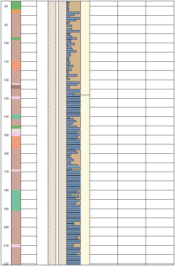
50 56
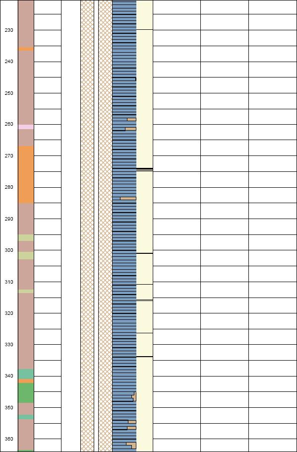
51 57
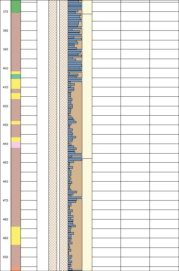
52 58
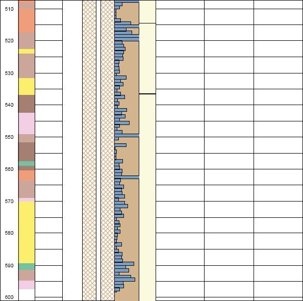
53 59
P Forsmark site investigation. Drilling of the telescopic borehole KFM01A at drilling site DS1
 P-03-32 Forsmark site investigation Drilling of the telescopic borehole KFM01A at drilling site DS1 Lars-Åke Claesson, Mirab Mineral Resurser AB Göran Nilsson, GNC AB May 2004 Svensk Kärnbränslehantering
P Forsmark site investigation. Drilling of the telescopic borehole KFM02B at drill site DS2. Lars-Åke Claesson, Mirab Mineral Resurser AB
 P-07-44 Forsmark site investigation Drilling of the telescopic borehole KFM02B at drill site DS2 Lars-Åke Claesson, Mirab Mineral Resurser AB Göran Nilsson, Anders Ullberg GNC AB September 2007 Svensk
P Äspö Hard Rock Laboratory. Ground magnetic survey at site for planned facility for calibration of borehole orientation equipment at Äspö
 P-12-10 Äspö Hard Rock Laboratory Ground magnetic survey at site for planned facility for calibration of borehole orientation equipment at Äspö Håkan Mattsson, GeoVista AB January 2012 Svensk Kärnbränslehantering
SVENSK STANDARD SS-ISO :2010/Amd 1:2010
 SVENSK STANDARD SS-ISO 14839-1:2010/Amd 1:2010 Fastställd/Approved: 2010-11-08 Publicerad/Published: 2010-11-30 Utgåva/Edition: 1 Språk/Language: engelska/english ICS: 01.040.17; 17.160 Vibration och stöt
Isolda Purchase - EDI
 Isolda Purchase - EDI Document v 1.0 1 Table of Contents Table of Contents... 2 1 Introduction... 3 1.1 What is EDI?... 4 1.2 Sending and receiving documents... 4 1.3 File format... 4 1.3.1 XML (language
P Forsmark site investigation
 P-05-21 Forsmark site investigation Comparison of measured EC in selected fractures in boreholes KFM02A, KFM03A and KFM04A from difference flow logging and hydro-geochemical characterization Analysis of
Boiler with heatpump / Värmepumpsberedare
 Boiler with heatpump / Värmepumpsberedare QUICK START GUIDE / SNABBSTART GUIDE More information and instruction videos on our homepage www.indol.se Mer information och instruktionsvideos på vår hemsida
Beijer Electronics AB 2000, MA00336A, 2000-12
 Demonstration driver English Svenska Beijer Electronics AB 2000, MA00336A, 2000-12 Beijer Electronics AB reserves the right to change information in this manual without prior notice. All examples in this
Rev No. Magnetic gripper 3
 Magnetic gripper 1 Magnetic gripper 2 Magnetic gripper 3 Magnetic gripper 4 Pneumatic switchable permanent magnet. A customized gripper designed to handle large objects in/out of press break/laser cutting
säkerhetsutrustning / SAFETY EQUIPMENT
 säkerhetsutrustning / SAFETY EQUIPMENT Hastighetsvakt / Speed monitor Kellves hastighetsvakter används för att stoppa bandtransportören när dess hastighet sjunker under beräknade minimihastigheten. Kellve
3 rd October 2017
 3 rd October 2017 Failures of Scaffold False work Failures Form work Bursting Trench Support Failure Hoarding Failures Can be expensive and result in fatalities and serious injuries Cardiff
SVENSK STANDARD SS-ISO 8734
 SIS - Standardiseringskommissionen i Sverige Handläggande organ SMS, SVERIGES MEKANSTANDARDISERING SVENSK STANDARD SS-ISO 8734 Fastställd Utgåva Sida Registering 1992-11-16 1 1 (1+8) SMS reg 27.1128 SIS
P Forsmark site investigation. Hydraulic interference test with borehole HFM33 used as pumping borehole, November of 2007
 P-07-229 Forsmark site investigation Hydraulic interference test with borehole HFM33 used as pumping borehole, November of 2007 Kristoffer Gokall-Norman, Jan-Erik Ludvigson, Geosigma AB May 2008 Svensk
BBT057/ BBC057 BBCD057/ BBT057-NL HOLDEN COLORADO 9/2016+ HOLDEN TRAILBLAZER WD & 4WD Models
 INSTALLATION GUIDE BBT057/ BBC057 BBCD057/ BBT057-NL HOLDEN COLORADO 9/2016+ HOLDEN TRAILBLAZER 2017+ 2WD & 4WD Models Ironman 4x4 BBT/ BBC/ BBCD/BBT057-NL Bull Bars fit to a Holden Colorado 9/2016+ It
Isometries of the plane
 Isometries of the plane Mikael Forsberg August 23, 2011 Abstract Här följer del av ett dokument om Tesselering som jag skrivit för en annan kurs. Denna del handlar om isometrier och innehåller bevis för
Kundfokus Kunden och kundens behov är centrala i alla våra projekt
 D-Miljö AB bidrar till en renare miljö genom projekt där vi hjälper våra kunder att undersöka och sanera förorenad mark och förorenat grundvatten. Vi bistår dig som kund från projektets start till dess
Module 6: Integrals and applications
 Department of Mathematics SF65 Calculus Year 5/6 Module 6: Integrals and applications Sections 6. and 6.5 and Chapter 7 in Calculus by Adams and Essex. Three lectures, two tutorials and one seminar. Important
SVENSK STANDARD SS-ISO 8779:2010/Amd 1:2014
 SVENSK STANDARD SS-ISO 8779:2010/Amd 1:2014 Fastställd/Approved: 2014-07-04 Publicerad/Published: 2014-07-07 Utgåva/Edition: 1 Språk/Language: engelska/english ICS: 23.040.20; 65.060.35; 83.140.30 Plaströrssystem
TEXTURED EASY LOCK BLOCK INSTALLATION GUIDE. australianpaving.com.au
 TEXTURED EASY LOCK BLOCK INSTALLATION GUIDE 1800 191 131 australianpaving.com.au TEXTURED EASY LOCK BLOCK The Textured Easy Lock Block retaining wall system is the premium retaining wall product for near
STANDARD. UTM Ingegerd Annergren UTMS Lina Orbéus. UTMD Anders Johansson UTMS Jan Sandberg
 1(7) Distribution: Scania, Supplier Presskruvar med rundat huvud - Metrisk gänga med grov delning Innehåll Sida Orientering... 1 Ändringar från föregående utgåva... 1 1 Material och hållfasthet... 1 2
Viktig information för transmittrar med option /A1 Gold-Plated Diaphragm
 Viktig information för transmittrar med option /A1 Gold-Plated Diaphragm Guldplätering kan aldrig helt stoppa genomträngningen av vätgas, men den får processen att gå långsammare. En tjock guldplätering
GERDA Cryostat Rn emanation
 GERDA Cryostat Rn emanation K.T. Knöpfle, B. Schwingenheuer, H. Simgen, G. Zuzel MPI für Kernphysik, Heidelberg General remarks Tolerable rate: ~8 (14) mbq 10-4 cts/(kg kev y) assuming homogenous Rn distribution
A study of the performance
 A study of the performance and utilization of the Swedish railway network Anders Lindfeldt Royal Institute of Technology 2011-02-03 Introduction The load on the railway network increases steadily, and
Information technology Open Document Format for Office Applications (OpenDocument) v1.0 (ISO/IEC 26300:2006, IDT) SWEDISH STANDARDS INSTITUTE
 v1.0 (ISO/IEC 26300:2006, IDT) SWEDISH STANDARDS INSTITUTE") SVENSK STANDARD SS-ISO/IEC 26300:2008 Fastställd/Approved: 2008-06-17 Publicerad/Published: 2008-08-04 Utgåva/Edition: 1 Språk/Language: engelska/english ICS: 35.240.30 Information technology Open Document
SVENSK STANDARD SS-ISO/IEC 26300:2008 Fastställd/Approved: 2008-06-17 Publicerad/Published: 2008-08-04 Utgåva/Edition: 1 Språk/Language: engelska/english ICS: 35.240.30 Information technology Open Document
Preschool Kindergarten
 Preschool Kindergarten Objectives CCSS Reading: Foundational Skills RF.K.1.D: Recognize and name all upper- and lowercase letters of the alphabet. RF.K.3.A: Demonstrate basic knowledge of one-toone letter-sound
Dokumentnamn Order and safety regulations for Hässleholms Kretsloppscenter. Godkänd/ansvarig Gunilla Holmberg. Kretsloppscenter
 1(5) The speed through the entire area is 30 km/h, unless otherwise indicated. Beware of crossing vehicles! Traffic signs, guardrails and exclusions shall be observed and followed. Smoking is prohibited
Installation Instructions
 Installation Instructions (Cat. No. 1794-IE8 Series B) This module mounts on a 1794 terminal base unit. 1. Rotate keyswitch (1) on terminal base unit (2) clockwise to position 3 as required for this type
Schenker Privpak AB Telefon VAT Nr. SE Schenker ABs ansvarsbestämmelser, identiska med Box 905 Faxnr Säte: Borås
 Schenker Privpak AB Interface documentation for web service packageservices.asmx 2012-09-01 Version: 1.0.0 Doc. no.: I04304b Sida 2 av 7 Revision history Datum Version Sign. Kommentar 2012-09-01 1.0.0
Företagsnamn: Grundfos Skapad av: Magnus Johansson Tel: +46(0) Datum:
 Datum:") Position Antal Beskrivning 1 HYDRO MULTI-E CRIE5-1 Art.nr.: 9913311 OBS! Bilden på produkten kan avvika från aktuell produkt GRUNDFOS Hydro Multi-E booster sets are designed for the transfer and pressure
Position Antal Beskrivning 1 HYDRO MULTI-E CRIE5-1 Art.nr.: 9913311 OBS! Bilden på produkten kan avvika från aktuell produkt GRUNDFOS Hydro Multi-E booster sets are designed for the transfer and pressure
District Application for Partnership
 ESC Region Texas Regional Collaboratives in Math and Science District Application for Partnership 2013-2014 Applying for (check all that apply) Math Science District Name: District Contacts Name E-mail
MCP-16RC, Air Purification
 Kompakt patronfilter med tryckstötsrensning. MCP-16RC Air Purification Tower är ett kompakt patronfilter för decentraliserad luftrening inomhus, där luft återåtervinning är möjlig. Den kompakta filterenheten
SVENSK STANDARD SS-ISO 2338
 SIS Standardiseringskommissionen i Sverige Handläggande organ SMS, SVERIGES MEKANSTANDARDISERING SVENSK STANDARD SS-ISO 2338 Fastställd Utgåva Sida Registrering 1992-11-16 1 1 (1+8) SMS reg 27.1113 SIS
Parking garage, Gamletull. MDM-piles, pre-installation testing RÄTT FRÅN GRUNDEN!
 Parking garage, Gamletull MDM-piles, pre-installation testing Gamletull, MDM-pålar 1 CPT tests Gamletull, MDM-pålar 2 CPT test results Cone resistance Undrained shear strength Gamletull, MDM-pålar 3 Interpretation
Support Manual HoistLocatel Electronic Locks
 Support Manual HoistLocatel Electronic Locks 1. S70, Create a Terminating Card for Cards Terminating Card 2. Select the card you want to block, look among Card No. Then click on the single arrow pointing
FÖRBERED UNDERLAG FÖR BEDÖMNING SÅ HÄR
 FÖRBERED UNDERLAG FÖR BEDÖMNING SÅ HÄR Kontrollera vilka kurser du vill söka under utbytet. Fyll i Basis for nomination for exchange studies i samråd med din lärare. För att läraren ska kunna göra en korrekt
Metodprov för kontroll av svetsmutterförband Kontrollbestämmelse Method test for inspection of joints of weld nut Inspection specification
 Stämpel/Etikett Security stamp/lable Metodprov för kontroll av svetsmutterförband Kontrollbestämmelse Method test for inspection of joints of weld nut Inspection specification Granskad av Reviewed by Göran
Signatursida följer/signature page follows
 Styrelsens i Flexenclosure AB (publ) redogörelse enligt 13 kap. 6 och 14 kap. 8 aktiebolagslagen över förslaget till beslut om ökning av aktiekapitalet genom emission av aktier och emission av teckningsoptioner
Users manual Bruksanvisning Gebrauchanweisung Guide d instructions
 Multi-pressure bucket pump Bärbar fettpump hochdruck abschmierpumpe distributeur manuel de graisse Users manual Bruksanvisning Gebrauchanweisung Guide d instructions 11018-1 - 815850 R02/03 IMPORTANT:
SWESIAQ Swedish Chapter of International Society of Indoor Air Quality and Climate
 Swedish Chapter of International Society of Indoor Air Quality and Climate Aneta Wierzbicka Swedish Chapter of International Society of Indoor Air Quality and Climate Independent and non-profit Swedish
BBT042/ BBC042/ BBCD042 NISSAN NAVARA D40 V STX & PATHFINDER R WD & 4WD Models
 INSTALLATION GUIDE BBT042/ BBC042/ BBCD042 NISSAN NAVARA D40 V6 2010+ STX & PATHFINDER R51 2010+ 2WD & 4WD Models Ironman 4x4 BBT/ BBC/ BBCD042 Bull Bars fit to a Nissan Navara D40 STX & Pathfinder R51.
Utfärdad av Compiled by Tjst Dept. Telefon Telephone Datum Date Utg nr Edition No. Dokumentnummer Document No.
 Stämpel/Etikett Security stamp/lable PROVNINGSBESTÄMMELSE OFRSTRANDE PROVNING AV STÅLGJUTGODS TEST SPECIFICATION NON-DESTRUCTIVE TESTING OF STEEL CASTINGS Granskad av Reviewed by Göran Magnusson Tjst Dept.
SVENSK STANDARD SS-EN ISO 19108:2005/AC:2015
 SVENSK STANDARD SS-EN ISO 19108:2005/AC:2015 Fastställd/Approved: 2015-07-23 Publicerad/Published: 2016-05-24 Utgåva/Edition: 1 Språk/Language: engelska/english ICS: 35.240.70 Geografisk information Modell
Accepterad monteringsanvisning 2016:1
 EN Table of contents 1 Instructions for use / assembly instructions 2 Assembly 4-6 Adjustment 7 Dimensions 8 Flow diagram 9 Test certificate 9 Operation 10 Spare parts 11 Cleaning 12 Contact information
Documentation SN 3102
 This document has been created by AHDS History and is based on information supplied by the depositor /////////////////////////////////////////////////////////// THE EUROPEAN STATE FINANCE DATABASE (Director:
INDUKTIV SLINGDETEKTOR INDUCTIVE LOOP DETECTOR
 INDUKTIV SLINGDETEKTOR INDUCTIVE LOOP DETECTOR Slingdetektorn används som ett alternativ till mekaniska gränslägen, momentbrytare eller annat gränsläge i gödselrännor. Detektorn är kopplad till en trådslinga
Accepterad monteringsanvisning 2016:1. Metris (RSK: ) Metris S (RSK: ) Metris (RSK: )
 Metris S (RSK: ) Metris (RSK: )") EN Table of contents 1 Instructions for use / assembly instructions 2 Assembly 4-5 Adjustment 6 Operation 7 Dimensions 8-9 Flow diagram 8-9 Spare parts 10-12 Cleaning 13 Test certificate 14 Contact information
EN Table of contents 1 Instructions for use / assembly instructions 2 Assembly 4-5 Adjustment 6 Operation 7 Dimensions 8-9 Flow diagram 8-9 Spare parts 10-12 Cleaning 13 Test certificate 14 Contact information
Uttagning för D21E och H21E
 Uttagning för D21E och H21E Anmälan till seniorelitklasserna vid O-Ringen i Kolmården 2019 är öppen fram till och med fredag 19 juli klockan 12.00. 80 deltagare per klass tas ut. En rangordningslista med
Accomodations at Anfasteröd Gårdsvik, Ljungskile
 Accomodations at Anfasteröd Gårdsvik, Ljungskile Anfasteröd Gårdsvik is a campsite and resort, located right by the sea and at the edge of the forest, south west of Ljungskile. We offer many sorts of accommodations
Montageanvisning Airway system 1000/1500 Assembly instruction Airway system 1000/1500
 S.Det är lämpligt att denna information överlämnas till användaren av anläggningen. GB. It is appropriate that this information is passed on to the user of the installation. D. Diese informationen sind
Accepterad monteringsanvisning 2016:1. Talis S (RSK: ) Talis S (RSK: ) 1 (12)
 Talis S (RSK: ) 1 (12)") EN Table of contents 1 Instructions for use / assembly instructions 2 Assembly 4-5 Adjustment 6 Dimensions 7 Flow diagram 7 Operation 8 Spare parts 9 Cleaning 10 Test certificate 11 Contact information
EN Table of contents 1 Instructions for use / assembly instructions 2 Assembly 4-5 Adjustment 6 Dimensions 7 Flow diagram 7 Operation 8 Spare parts 9 Cleaning 10 Test certificate 11 Contact information
P Site investigation SFR. Hydro Monitoring Program. Report for May 2008 August Göran Nyberg, Eva Wass Geosigma AB.
 P-09-65 Site investigation SFR Hydro Monitoring Program Report for May 2008 August 2009 Göran Nyberg, Eva Wass Geosigma AB October 2009 Svensk Kärnbränslehantering AB Swedish Nuclear Fuel and Waste Management
Windlass Control Panel v1.0.1
 SIDE-POWER Windlass Systems 86-08950 Windlass Control Panel v1.0.1 EN Installation manual Behåll denna manual ombord! S Installations manual SLEIPNER AB Kilegatan 1 452 33 Strömstad Sverige Tel: +46 525
E4 Sundsvall Sundsvallsbron
 E4 Sundsvall Sundsvallsbron E4 Sundsvall LEVERANTÖRSDAG EN NY VÄG. 1000 2009 NYA MÖJLIGHETER One new road. 1000 new opportunities. Ove Malmberg, Assistant Project Manager 2 2014-10-10 Project E4 Sundsvall
2.1 Installation of driver using Internet Installation of driver from disk... 3
 &RQWHQW,QQHKnOO 0DQXDOÃ(QJOLVKÃ'HPRGULYHU )RUHZRUG Ã,QWURGXFWLRQ Ã,QVWDOOÃDQGÃXSGDWHÃGULYHU 2.1 Installation of driver using Internet... 3 2.2 Installation of driver from disk... 3 Ã&RQQHFWLQJÃWKHÃWHUPLQDOÃWRÃWKHÃ3/&ÃV\VWHP
Accepterad monteringsanvisning 2016:1. Talis S (RSK: ) Talis S 100 CoolStart (RSK: )
 Talis S 100 CoolStart (RSK: )") EN Table of contents 1 Instructions for use / assembly instructions 2 Assembly 4-5 Adjustment 6 Dimensions 7 Flow diagram 7 Operation 8 Spare parts 9 Cleaning 10 Test certificate 11 Contact information
EN Table of contents 1 Instructions for use / assembly instructions 2 Assembly 4-5 Adjustment 6 Dimensions 7 Flow diagram 7 Operation 8 Spare parts 9 Cleaning 10 Test certificate 11 Contact information
Sammanfattning hydraulik
 Sammanfattning hydraulik Bernoullis ekvation Rörelsemängdsekvationen Energiekvation applikationer Rörströmning Friktionskoefficient, Moody s diagram Pumpsystem BERNOULLI S EQUATION 2 p V z H const. Quantity
Utfärdad av Compiled by Tjst Dept. Telefon Telephone Datum Date Utg nr Edition No. Dokumentnummer Document No.
 Utfärdad av Compiled by Tjst Dept. Telefon Telephone David Andersson BUM 733 684 Stämpel/Etikett Security stamp/label ÅTDRAGNINGSMOMENT TIGHTENING TORQUE Granskad av Reviewed by Göran Magnusson Tjst Dept.
Oförstörande provning (NDT) i Del M Subpart F/Del 145-organisationer
 i Del M Subpart F/Del 145-organisationer") Oförstörande provning (NDT) i Del M Subpart F/Del 145-organisationer Ref. Del M Subpart F & Del 145 2012-05-02 1 Seminarium för Teknisk Ledning HKP 3maj, 2012, Arlanda Inledning Allmänt Viktigare krav
Oförstörande provning (NDT) i Del M Subpart F/Del 145-organisationer Ref. Del M Subpart F & Del 145 2012-05-02 1 Seminarium för Teknisk Ledning HKP 3maj, 2012, Arlanda Inledning Allmänt Viktigare krav
The Arctic boundary layer
 The Arctic boundary layer Interactions with the surface, and clouds, as learned from observations (and some modeling) Michael Tjernström Department of Meteorology & the Bert Bolin Center for Climate Research,
PRESTANDADEKLARATION. Nr 0015 SV
 PRESTANDADEKLARATION Nr 0015 SV 1. Produkttypens unika identifikationskod: fischer Anchor bolt FBN II, FBN II A4 2. Avsedd användning/avsedda användningar: Produkt Avsedd användning/användningar Kraftkontrollerat
CompactAIR Center Ventilation - Filtrering - Uppvärmning CompactAIR Center Ventilation - Filtration - Heating
 CompactAIR / CompactAIR CompactAIR Center Ventilation - Filtrering - Uppvärmning CompactAIR Center Ventilation - Filtration - Heating Typenschlüssel / Type Code Beteckning / Type code Compact AIR / CompactAIR
Styrteknik: Binära tal, talsystem och koder D3:1
 Styrteknik: Binära tal, talsystem och koder D3:1 Digitala kursmoment D1 Boolesk algebra D2 Grundläggande logiska funktioner D3 Binära tal, talsystem och koder Styrteknik :Binära tal, talsystem och koder
Accepterad monteringsanvisning 2016:1. Focus (RSK: ) 1 (12)
 1 (12)") EN Table of contents 1 Instructions for use / assembly instructions 2 Assembly 4 Adjustment 5 Dimensions 6 Flow diagram 6 Operation 7 Spare parts 8 Cleaning 9 Test certificate 10 Contact information 12
EN Table of contents 1 Instructions for use / assembly instructions 2 Assembly 4 Adjustment 5 Dimensions 6 Flow diagram 6 Operation 7 Spare parts 8 Cleaning 9 Test certificate 10 Contact information 12
PRESTANDADEKLARATION. Nr 0019 SV. bilagor B 1 - B 9
 PRESTANDADEKLARATION Nr 0019 SV 1. Produkttypens unika identifikationskod: fischer Highbond-Anchor FHB II 2. Avsedd användning/avsedda användningar: Produkt Kemiskt ankare för användning i betong Avsedd
INSTALLATION INSTRUCTIONS
 INSTALLATION - REEIVER INSTALLATION INSTRUTIONS RT0 RF WIRELESS ROOM THERMOSTAT AND REEIVER MOUNTING OF WALL MOUTING PLATE - Unscrew the screws under the - Pack contains... Installation - Receiver... Mounting
AquaTeq Sweden AB Radarvägen 12 SE KALMAR. PHONE: +46 (0) INTERNET:
 INTERNET:") FLEX-SYSTEM Slang-Flex har utvecklats till ett helt system med olika verktyg och funktioner. Vi kallar det Flex- System. Med Flex-System kopplas en mängd olika slangsparare, stensilar, skopor, spadar mm
FLEX-SYSTEM Slang-Flex har utvecklats till ett helt system med olika verktyg och funktioner. Vi kallar det Flex- System. Med Flex-System kopplas en mängd olika slangsparare, stensilar, skopor, spadar mm
FORSKNINGSKOMMUNIKATION OCH PUBLICERINGS- MÖNSTER INOM UTBILDNINGSVETENSKAP
 FORSKNINGSKOMMUNIKATION OCH PUBLICERINGS- MÖNSTER INOM UTBILDNINGSVETENSKAP En studie av svensk utbildningsvetenskaplig forskning vid tre lärosäten VETENSKAPSRÅDETS RAPPORTSERIE 10:2010 Forskningskommunikation
Accepterad monteringsanvisning 2016:1. Ecos M CoolStart (RSK: ) Ecos L CoolStart (RSK: ) 1 (12)
 Ecos L CoolStart (RSK: ) 1 (12)") EN Table of contents 1 Instructions for use / assembly instructions 2 Assembly 4-5 Adjustment 6 Dimensions 7 Flow diagram 7 Operation 8 Spare parts 9 Cleaning 10 Test certificate 11 Contact information
EN Table of contents 1 Instructions for use / assembly instructions 2 Assembly 4-5 Adjustment 6 Dimensions 7 Flow diagram 7 Operation 8 Spare parts 9 Cleaning 10 Test certificate 11 Contact information
IRAB Mottagare sida 2-5 Tele Radio AB Mottagare sida 6
 IRAB Mottagare sida -5 Tele Radio AB Mottagare sida 6 Installation of receiver type smd 700 4 RELAY FUNCTIONS / -4 VAC/DC PCB TYPE NO: LWEG 4L Rev: 95-09 Installation: Install the receivers in a protected
7!34% 7!34% 50-51 7!34% 52-53,/7 54-55
 50-5 5-53 54-55 waste oil is evacuated directly from the engine to the waste oil storage tank. Both personal contact with the waste oil and mobile units are avoided. tas spilloljan direkt från motorn till
Tunga metaller / Heavy metals ICH Q3d & Farmakope. Rolf Arndt Cambrex Karlskoga
 Tunga metaller / Heavy metals ICH Q3d & Farmakope Rolf Arndt Cambrex Karlskoga Tunga metaller / Heavy metals Rolf Arndt -Quality Assurance Cambrex Karlskoga - Svenska Farmakopekommitten / Working Party
 BÄNKVÅG / BENCH SCALE Modell : SW-III / Model : SW-III ANVÄNDARMANUAL / USER MANUAL SW-III WWW.LIDEN-WEIGHING.SE 2014-03-26 OBS! Under vågen sitter en justerbar skruv (se bild). Standardinställning är
EASA Standardiseringsrapport 2014
 EASA Standardiseringsrapport 2014 Inför EASA Standardiseringsinspektion hösten 2016 Presentatör Johan Brunnberg, Flygteknisk Inspektör & Del-M Koordinator Sjö- och luftfartsavdelningen Enheten för operatörer,
EBBA2 European Breeding Bird Atlas
 Methodology Sergi Herrando, Verena Keller, Petr Voříšek et al. objectives 1. To document breeding evidence for all bird species at a resolution of 50x50 km 2. To estimate abundance for all bird species
Skyddande av frågebanken
 Presentatör Martin Francke Flygteknisk inspektör Sjö- och luftfartsavdelningen Enheten för operatörer, fartyg och luftfartyg Sektionen för underhålls- och tillverkningsorganisationer 1 147.A.145 Privileges
The Municipality of Ystad
 The Municipality of Ystad Coastal management in a local perspective TLC The Living Coast - Project seminar 26-28 nov Mona Ohlsson Project manager Climate and Environment The Municipality of Ystad Area:
Materialplanering och styrning på grundnivå. 7,5 högskolepoäng
 Materialplanering och styrning på grundnivå Provmoment: Ladokkod: Tentamen ges för: Skriftlig tentamen TI6612 Af3-Ma, Al3, Log3,IBE3 7,5 högskolepoäng Namn: (Ifylles av student) Personnummer: (Ifylles
Förbundsutskott 32, broar och tunnlar
 Förbundsutskott 32, broar och tunnlar Utmärkelse till en framstående konstruktion inom bro- och tunnelområdet www.nvfnorden.org Stadgar i korthet: För ingenjörskonsten viktiga konstruktioner Behöver inte
Teknisk specifikation SIS-ISO/TS :2010
 Teknisk specifikation SIS-ISO/TS 128-71:2010 Publicerad/Published: 2010-11-30 Utgåva/Edition: 1 Språk/Language: engelska/english ICS: 01.100.20 Ritregler Allmänna ritregler Del 71: Förenklat ritsätt för
D-RAIL AB. All Rights Reserved.
 2 3 4 5 6 Photo: Svante Fält 7 8 9 ägare ägare /förvaltare huvudman mätning operatör DATA underhållare underhållare 9 The hardware 10 SENSORS: Cutting edge technology designed for minimum maintenance and
INVESTIGATION OF LAKE HÖRNTRÄSKET, LYCKSELE KOMMUN
 2005/01/20 INVESTIGATION OF LAKE HÖRNTRÄSKET, LYCKSELE KOMMUN Prepared by: Audrone Zaliauskiene Repport No 0501K50 Telefon: +46706441166 Passive water sampling using DGT Passive water sampling is a sampling
Protected areas in Sweden - a Barents perspective
 Protected areas in Sweden - a Barents perspective Olle Höjer Swedish Environmental Protection Agency Naturvårdsverket Swedish Environmental Protection Agency 2013-04-03 1 The fundamental framework for
Schenker Privpak AB Telefon 033-178300 VAT Nr. SE556124398001 Schenker ABs ansvarsbestämmelser, identiska med Box 905 Faxnr 033-257475 Säte: Borås
 Schenker Privpak AB Interface documentation for web service packageservices.asmx 2010-10-21 Version: 1.2.2 Doc. no.: I04304 Sida 2 av 14 Revision history Datum Version Sign. Kommentar 2010-02-18 1.0.0
Surfaces for sports areas Determination of vertical deformation. Golvmaterial Sportbeläggningar Bestämning av vertikal deformation
 SVENSK STANDARD SS-EN 14809:2005/AC:2007 Fastställd/Approved: 2007-11-05 Publicerad/Published: 2007-12-03 Utgåva/Edition: 1 Språk/Language: engelska/english ICS: 97.220.10 Golvmaterial Sportbeläggningar
8 < x 1 + x 2 x 3 = 1, x 1 +2x 2 + x 4 = 0, x 1 +2x 3 + x 4 = 2. x 1 2x 12 1A är inverterbar, och bestäm i så fall dess invers.
 MÄLARDALENS HÖGSKOLA Akademin för utbildning, kultur och kommunikation Avdelningen för tillämpad matematik Examinator: Erik Darpö TENTAMEN I MATEMATIK MAA150 Vektoralgebra TEN1 Datum: 9januari2015 Skrivtid:
Swedish adaptation of ISO TC 211 Quality principles. Erik Stenborg
 Swedish adaptation of ISO TC 211 Quality principles The subject How to use international standards Linguistic differences Cultural differences Historical differences Conditions ISO 19100 series will become
Module 1: Functions, Limits, Continuity
 Department of mathematics SF1625 Calculus 1 Year 2015/2016 Module 1: Functions, Limits, Continuity This module includes Chapter P and 1 from Calculus by Adams and Essex and is taught in three lectures,
IMPORTANT! RETAIN FOR FUTURE REFERENCE PLEASE READ CAREFULLY VIKTIGT! BEHÅLL FÖR FRAMTIDA REFERENS LÄS IGENOM INSTRUKTIONSMANUALEN
 Heart & Stripes Junior Bed Instructions Manual Instruktions Manual IMPORTANT! RETAIN FOR FUTURE REFERENCE PLEASE READ CAREFULLY VIKTIGT! BEHÅLL FÖR FRAMTIDA REFERENS LÄS IGENOM INSTRUKTIONSMANUALEN Thank
GOLD SD 14-40. Med styrenhet/with control unit. Fläkt/ Fan. Utan filter/ Without filter. Fläkt/Fan. Fläkt/ Fan. Med filter/ With filter.
 GOLD SD 4-40 Med styrenhet/with control unit Skiss visar styrenhet för aggregat med inspektionssida vänster, styrenhet för aggregat med inspektionssida höger ser något annorlunda ut, men principen är lika./
Why Steam Engine again??
 Småskalig ångteknik för värmeåtervinning inom Stålindustrin med modern ångmotor 1 Why Steam Engine again?? Rankine power cycles is more fuel flexible than any other power cycles but in the small scale
Agenda. Tid Aktivitet Föreläsare Åtgång tid 08:30 Registrering vid TS recep. Transport till våning 5.
 Agenda Tid Aktivitet Föreläsare Åtgång tid 08:30 Registrering vid TS recep. Transport till våning 5. Dennis, Jerry och Gun. 30 min. 09:00 Intro. (Agendan, lokaler, m.m.) Dennis / Jerry/Gun 15 min 09:15
P650 - Takscreen. Installationsguide EN
 P650 - Takscreen Installationsguide 1309-150507EN V650-Tallinn Installation manual Montera främre linhjul 12 13 Placera linan över linhjulet och skruva tillbaka täcklocket på linhjulhuset (7). Öppna linhjulshuset
 BÄNKVÅG / BENCH SCALE ANVÄNDARMANUAL / USER MANUAL SW-III www.liden-weighing.com Svenska OBS! Under vågen sitter en justerbar skruv (se bild). Standardinställning är den för vägning. Om ni vill rengöra
EASA FTL (Flygarbetstid)
") EASA FTL EASA FTL (Flygarbetstid) Ett urval av reglerna Christer Ullvetter Transportstyrelsen i Norrköping 1 Air taxi operation New definition Air taxi operation means, for the purpose of flight time and
EASA FTL EASA FTL (Flygarbetstid) Ett urval av reglerna Christer Ullvetter Transportstyrelsen i Norrköping 1 Air taxi operation New definition Air taxi operation means, for the purpose of flight time and
RADIATION TEST REPORT. GAMMA: 30.45k, 59.05k, 118.8k/TM1019 Condition D
 RADIATION TEST REPORT PRODUCT: OP47AYQMLL Die Type: 147X FILE: OP47_LDR.xlsx DATE CODE: 95 GAMMA: 3.45k, 59.5k, 118.8k/TM119 Condition D GAMMA SOURCE: Co6 DOSE RATE: 8.6mRad(si)/s FACILITIES: University
Stiftelsen Allmänna Barnhuset KARLSTADS UNIVERSITET
 Stiftelsen Allmänna Barnhuset KARLSTADS UNIVERSITET National Swedish parental studies using the same methodology have been performed in 1980, 2000, 2006 and 2011 (current study). In 1980 and 2000 the studies
Webbregistrering pa kurs och termin
 Webbregistrering pa kurs och termin 1. Du loggar in på www.kth.se via den personliga menyn Under fliken Kurser och under fliken Program finns på höger sida en länk till Studieöversiktssidan. På den sidan
Accepterad monteringsanvisning 2016:1. Focus (RSK: ) Focus 100 CoolStart (RSK: ) (RSK: )
 Focus 100 CoolStart (RSK: ) (RSK: )") EN Table of contents 1 Instructions for use / assembly instructions 2 Assembly 4-5 Adjustment 6 Dimensions 7 Flow diagram 7 Operation 8 Spare parts 9-10 Cleaning 11 Test certificate 12 Contact information
EN Table of contents 1 Instructions for use / assembly instructions 2 Assembly 4-5 Adjustment 6 Dimensions 7 Flow diagram 7 Operation 8 Spare parts 9-10 Cleaning 11 Test certificate 12 Contact information