GBH Professional 3-28 DRE 3-28 DFR. Robert Bosch GmbH Power Tools Division Leinfelden-Echterdingen Germany.
|
|
|
- Ellen Bergqvist
- för 6 år sedan
- Visningar:
Transkript


1 OBJ_DOKU fm Page 1 Wednesday, April 8, :08 PM Robert Bosch GmbH Power Tools Division Leinfelden-Echterdingen Germany E56 ( ) PS / 320 UNI GBH Professional 3-28 DRE 3-28 DFR de Originalbetriebsanleitung en Original instructions fr Notice originale es Manual original pt Manual original it Istruzioni originali nl Oorspronkelijke gebruiksaanwijzing da Original brugsanvisning sv Bruksanvisning i original no Original driftsinstruks fi Alkuperäiset ohjeet el Πρωτότυπο οδηγιών χρήσης tr Orijinal işletme talimat pl Instrukcja oryginalna cs Původní návod k používání sk Pôvodný návod na použitie hu Eredeti használati utasítás ru Оригинальное руководство по эксплуатации uk Оригінальна інструкція з експлуатації ro Instrucţiuni originale bg Оригинална инструкция sr Originalno uputstvo za rad sl Izvirna navodila hr Originalne upute za rad et Algupärane kasutusjuhend lv Instrukcijas oriģinālvalodā lt Originali instrukcija


2 OBJ_BUCH book Page 3 Tuesday, April 7, :51 AM 3 GBH 3-28 DFR Professional GBH 3-28 DRE Professional E56 (7.4.09) Bosch Power Tools


3 OBJ_BUCH book Page 4 Tuesday, April 7, :51 AM 4 A B 3 11 X C 16 D E F (3x) E56 (7.4.09) Bosch Power Tools


4 OBJ_BUCH book Page 5 Tuesday, April 7, :51 AM 5 G H J I K 12 L X E56 (7.4.09) Bosch Power Tools
5 OBJ_BUCH book Page 18 Tuesday, April 7, :51 AM 18 English en Safety Notes General Power Tool Safety Warnings WARNING Read all safety warnings and all instructions. Failure to follow the warnings and instructions may result in electric shock, fire and/or serious injury. Save all warnings and instructions for future reference. The term power tool in the warnings refers to your mains-operated (corded) power tool or battery-operated (cordless) power tool. 1) Work area safety a) Keep work area clean and well lit. Cluttered or dark areas invite accidents. b) Do not operate power tools in explosive atmospheres, such as in the presence of flammable liquids, gases or dust. Power tools create sparks which may ignite the dust or fumes. c) Keep children and bystanders away while operating a power tool. Distractions can cause you to lose control. 2) Electrical safety a) Power tool plugs must match the outlet. Never modify the plug in any way. Do not use any adapter plugs with earthed (grounded) power tools. Unmodified plugs and matching outlets will reduce risk of electric shock. b) Avoid body contact with earthed or grounded surfaces, such as pipes, radiators, ranges and refrigerators. There is an increased risk of electric shock if your body is earthed or grounded. c) Do not expose power tools to rain or wet conditions. Water entering a power tool will increase the risk of electric shock. d) Do not abuse the cord. Never use the cord for carrying, pulling or unplugging the power tool. Keep cord away from heat, oil, sharp edges and moving parts. Damaged or entangled cords increase the risk of electric shock. e) When operating a power tool outdoors, use an extension cord suitable for outdoor use. Use of a cord suitable for outdoor use reduces the risk of electric shock. f) If operating a power tool in a damp location is unavoidable, use a residual current device (RCD) protected supply. Use of an RCD reduces the risk of electric shock. 3) Personal safety a) Stay alert, watch what you are doing and use common sense when operating a power tool. Do not use a power tool while you are tired or under the influence of drugs, alcohol or medication. A moment of inattention while operating power tools may result in serious personal injury. b) Use personal protective equipment. Always wear eye protection. Protective equipment such as dust mask, non-skid safety shoes, hard hat, or hearing protection used for appropriate conditions will reduce personal injuries. c) Prevent unintentional starting. Ensure the switch is in the off-position before connecting to power source and/or battery pack, picking up or carrying the tool. Carrying power tools with your finger on the switch or energising power tools that have the switch on invites accidents. d) Remove any adjusting key or wrench before turning the power tool on. A wrench or a key left attached to a rotating part of the power tool may result in personal injury. e) Do not overreach. Keep proper footing and balance at all times. This enables better control of the power tool in unexpected situations. f) Dress properly. Do not wear loose clothing or jewellery. Keep your hair, clothing and gloves away from moving parts. Loose clothes, jewellery or long hair can be caught in moving parts E56 (7.4.09) Bosch Power Tools
6 OBJ_BUCH book Page 19 Tuesday, April 7, :51 AM English 19 g) If devices are provided for the connection of dust extraction and collection facilities, ensure these are connected and properly used. Use of dust collection can reduce dust-related hazards. 4) Power tool use and care a) Do not force the power tool. Use the correct power tool for your application. The correct power tool will do the job better and safer at the rate for which it was designed. b) Do not use the power tool if the switch does not turn it on and off. Any power tool that cannot be controlled with the switch is dangerous and must be repaired. c) Disconnect the plug from the power source and/or the battery pack from the power tool before making any adjustments, changing accessories, or storing power tools. Such preventive safety measures reduce the risk of starting the power tool accidentally. d) Store idle power tools out of the reach of children and do not allow persons unfamiliar with the power tool or these instructions to operate the power tool. Power tools are dangerous in the hands of untrained users. e) Maintain power tools. Check for misalignment or binding of moving parts, breakage of parts and any other condition that may affect the power tool s operation. If damaged, have the power tool repaired before use. Many accidents are caused by poorly maintained power tools. f) Keep cutting tools sharp and clean. Properly maintained cutting tools with sharp cutting edges are less likely to bind and are easier to control. g) Use the power tool, accessories and tool bits etc. in accordance with these instructions, taking into account the working conditions and the work to be performed. Use of the power tool for operations different from those intended could result in a hazardous situation. 5) Service a) Have your power tool serviced by a qualified repair person using only identical replacement parts. This will ensure that the safety of the power tool is maintained. Hammer Safety Warnings Wear ear protectors. Exposure to noise can cause hearing loss. Use auxiliary handle(s), if supplied with the tool. Loss of control can cause personal injury. Hold power tool by insulated gripping surfaces, when performing an operation where the cutting accessory may contact hidden wiring or its own cord. Cutting accessory contacting a live wire may make exposed metal parts of the power tool live and could give the operator an electric shock. Use suitable detectors to determine if utility lines are hidden in the work area or call the local utility company for assistance. Contact with electric lines can lead to fire and electric shock. Damaging a gas line can lead to explosion. Penetrating a water line causes property damage or may cause an electric shock. When working with the machine, always hold it firmly with both hands and provide for a secure stance. The power tool is guided more secure with both hands. Secure the workpiece. A workpiece clamped with clamping devices or in a vice is held more secure than by hand. Keep your workplace clean. Blends of materials are particularly dangerous. Dust from light alloys can burn or explode. Always wait until the machine has come to a complete stop before placing it down. The tool insert can jam and lead to loss of control over the power tool. Never use the machine with a damaged cable. Do not touch the damaged cable and pull the mains plug when the cable is damaged while working. Damaged cables increase the risk of an electric shock. Bosch Power Tools E56 (7.4.09)
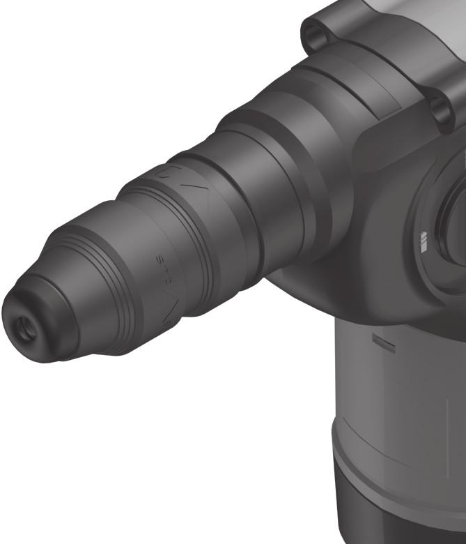
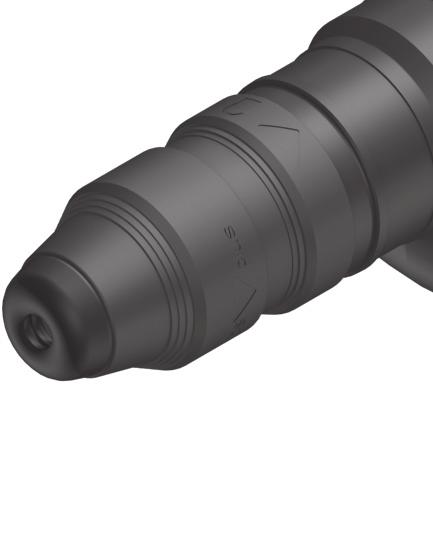
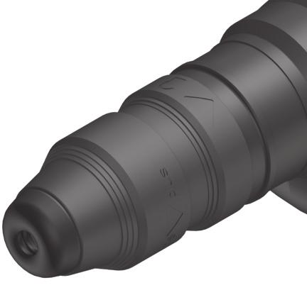
7 OBJ_BUCH book Page 20 Tuesday, April 7, :51 AM 20 English Products sold in GB only: Your product is fitted with an BS 1363/A approved electric plug with internal fuse (ASTA approved to BS 1362). If the plug is not suitable for your socket outlets, it should be cut off and an appropriate plug fitted in its place by an authorised customer service agent. The replacement plug should have the same fuse rating as the original plug. The severed plug must be disposed of to avoid a possible shock hazard and should never be inserted into a mains socket elsewhere. Products sold in AUS and NZ only: Use a residual current device (RCD) with a rated residual current of 30 ma or less. Functional Description Read all safety warnings and all instructions. Failure to follow the warnings and instructions may result in electric shock, fire and/or serious injury. While reading the operating instructions, unfold the graphics page for the machine and leave it open. Intended Use The machine is intended for hammer drilling in concrete, brick and stone, as well as for light chiselling work. It is also suitable for drilling without impact in wood, metal, ceramic and plastic. Machines with electronic control and right/left rotation are also suitable for screwdriving. Product Features The numbering of the product features refers to the illustration of the machine on the graphics page. 1 Quick change keyless chuck (GBH 3-28 DFR) 2 SDS-plus quick change chuck (GBH 3-28 DFR) 3 SDS-plus tool holder 4 Dust protection cap 5 Locking sleeve 6 Lock ring for rapid-change chuck (GBH 3-28 DFR) 7 On/Off switch 8 Release button for mode selector switch 9 Mode selector switch 10 Button for depth stop adjustment 11 Depth stop 12 Auxiliary handle 13 Rotational direction switch 14 Securing screw for key type drill chuck* 15 Key type drill chuck* 16 SDS-plus adapter shank for drill chuck* 17 Drill chuck mounting (GBH 3-28 DFR) 18 Identification grooves 19 Front sleeve of the quick change keyless chuck (GBH 3-28 DFR) 20 Retaining ring of the quick change keyless chuck (GBH 3-28 DFR) 21 Extraction sleeve of the dust extraction attachment* 22 Clamping screw for the dust extraction attachment* 23 Depth stop of the dust extraction attachment* 24 Telescopic pipe of the dust extraction attachment* 25 Wing bolt of the dust extraction attachment* 26 Guide pipe of the dust extraction attachment* 27 Universal bit holder with SDS-plus shank* *Accessories shown or described are not part of the standard delivery scope of the product. A complete overview of accessories can be found in our accessories program E56 (7.4.09) Bosch Power Tools
8 OBJ_BUCH book Page 21 Tuesday, April 7, :51 AM English 21 Technical Data Rotary Hammer GBH 3-28 DRE Professional GBH 3-28 DFR Professional Article number B3A B4A 0.. Speed control Stop rotation Right/left rotation Quick change chuck Rated power input W Impact frequency at rated speed min Impact energy per stroke J Rated speed min Tool holder SDS-plus SDS-plus Spindle collar diameter mm Permissible drilling diameter, max.: (also see page 23) Concrete* Brickwork (with core bit) Steel Wood Weight according to EPTA-Procedure 01/2003 kg Protection class /II /II * not suitable with core bit The values given are valid for nominal voltages [U] of 230/240 V. For lower voltage and models for specific countries, these values can vary. Please observe the article number on the type plate of your machine. The trade names of the individual machines may vary. mm mm mm mm Bosch Power Tools E56 (7.4.09)
9 OBJ_BUCH book Page 22 Tuesday, April 7, :51 AM 22 English Noise/Vibration Information Measured values determined according to EN Typically the A-weighted noise levels of the product are: Sound pressure level Sound power level Uncertainty K= Wear hearing protection! Vibration total values (triax vector sum) determined according to EN 60745: Hammer drilling into concrete: Vibrational emission value a h Uncertainty K Chiselling: Vibrational emission value a h Uncertainty K Drilling in metal: Vibrational emission value a h Uncertainty K Screwdriving without impact: Vibrational emission value a h Uncertainty K db(a) db(a) db m/s 2 m/s 2 m/s 2 m/s 2 m/s 2 m/s 2 GBH 3-28 DRE Professional GBH 3-28 DFR Professional m/s 2 <2.5 <2.5 m/s The vibration emission level given in this information sheet has been measured in accordance with a standardised test given in EN and may be used to compare one tool with another. It may be used for a preliminary assessment of exposure. The declared vibration emission level represents the main applications of the tool. However if the tool is used for different applications, with different accessories or poorly maintained, the vibration emission may differ. This may significantly increase the exposure level over the total working period. An estimation of the level of exposure to vibration should also take into account the times when the tool is switched off or when it is running but not actually doing the job. This may significantly reduce the exposure level over the total working period. Identify additional safety measures to protect the operator from the effects of vibration such as: maintain the tool and the accessories, keep the hands warm, organisation of work patterns < < E56 (7.4.09) Bosch Power Tools
10 OBJ_BUCH book Page 23 Tuesday, April 7, :51 AM English 23 Declaration of Conformity We declare under our sole responsibility that the product described under Technical Data is in conformity with the following standards or standardization documents: EN according to the provisions of the directives 2004/108/EC, 98/37/EC (until 28 Dec 2009), 2006/42/EC (from 29 Dec 2009). Technical file at: Robert Bosch GmbH, PT/ESC, D Leinfelden-Echterdingen Dr. Egbert Schneider Senior Vice President Engineering Dr. Eckerhard Strötgen Head of Product Certification Adjusting the Drilling Depth (see figure B) The required drilling depth X can be set with the depth stop 11. Press the button for the depth stop adjustment 10 and insert the depth stop into the auxiliary handle 12. The knurled surface of the depth stop 11 must face downward. Insert the SDS-plus drilling tool to the stop into the SDS-plus tool holder 3. Otherwise, the movability of the SDS-plus drilling tool can lead to incorrect adjustment of the drilling depth. Pull out the depth stop until the distance between the tip of the drill bit and the tip of the depth stop correspond with the desired drilling depth X. Robert Bosch GmbH, Power Tools Division D Leinfelden-Echterdingen Leinfelden, Selecting Drill Chucks and Tools Material Operating Mode Assembly Before any work on the machine itself, pull the mains plug. Concrete Ø 4 28 mm SDS-plus SDS-plus Auxiliary Handle Operate your machine only with the auxiliary handle 12. Rotating the Auxiliary Handle (see figure A) The auxiliary handle 12 can be set to any position for a secure and low-fatigue working posture. Turn the bottom part of the auxiliary handle 12 in counterclockwise direction and swivel the auxiliary handle 12 to the desired position. Then retighten the bottom part of the auxiliary handle 12 by turning in clockwise direction. Pay attention that the clamping band of the auxiliary handle is positioned in the groove on the housing as intended for. Brickwork Ø mm SDS-plus Steel Wood SDS-plus Ø 13 mm SDS-plus Ø 30 mm SDS-plus Bosch Power Tools E56 (7.4.09)
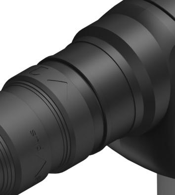
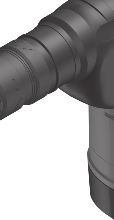
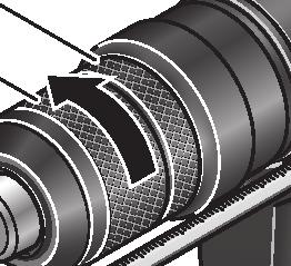
11 OBJ_BUCH book Page 24 Tuesday, April 7, :51 AM 24 English For hammer drilling and chiselling, SDS-plus tools are required that are inserted in the SDS-plus drill chuck. For drilling without impact in wood, metal, ceramic and plastic as well as for screwdriving, tools without SDS-plus are used (e.g., drills with cylindrical shank). For these tools, a keyless chuck or a key type drill chuck are required. GBH 3-28 DFR: The SDS-plus quick change chuck 2 can easily be replaced against the quick change keyless chuck 1 provided. Changing the Key Type Drill Chuck (GBH 3-28 DRE) To work with tools without SDS-plus (e.g., drills with cylindrical shank), a suitable drill chuck must be mounted (key type drill chuck or keyless chuck, accessories). Mounting the Key Type Drill Chuck (see figure C) Screw the SDS-plus adapter shank 16 into a key type drill chuck 15. Secure the key type drill chuck 15 with the securing screw 14. Please observe that the securing screw has a left-hand thread. Inserting the Key Type Drill Chuck (see figure C) Clean the shank end of the adapter shank and apply a light coat of grease. Insert the key type drill chuck with the adapter shank into the tool holder with a turning motion until it automatically locks. Check the locking effect by pulling the key type drill chuck. Removing/Inserting the Quick Change Chuck (GBH 3-28 DFR) Removing the Quick Change Chuck (see figure D) Pull the lock ring for the quick change chuck 6 toward the rear, hold it in this position and pull off the SDS-plus quick change chuck 2 or the quick change keyless chuck 1 toward the front. After removing, protect the replacement chuck against contamination. Inserting the Quick Change Chuck (see figure E) Use only model-specific original equipment and pay attention to the number of identification grooves 18. Only quick-change chucks with two or three identification grooves are permitted. When an unsuitable quick-change chuck is used, the application tool could fall out during operation. Before inserting, clean the quick change chuck and apply a light coat of grease to the shank end. Grasp the SDS-plus quick change chuck 2 or the quick change keyless chuck 1 completely with your hand. Slide the quick change chuck with a turning motion onto the drill chuck mounting 17 until a distinct latching noise is heard. The quick change chuck is automatically locked. Check the locking effect by pulling the quick change chuck. Removing the Key Type Drill Chuck Push the locking sleeve 5 toward the rear and pull out the key type drill chuck E56 (7.4.09) Bosch Power Tools
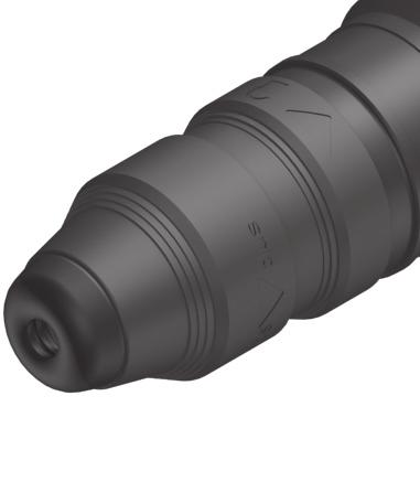
12 OBJ_BUCH book Page 25 Tuesday, April 7, :51 AM English 25 Changing the Tool The dust protection cap 4 largely prevents the entry of drilling dust into the tool holder during operation. When inserting the tool, take care that the dust protection cap 4 is not damaged. A damaged dust protection cap should be changed immediately. We recommend having this carried out by an after-sales service. Inserting SDS-plus Drilling Tools (see figure F) The SDS-plus drill chuck allows for simple and convenient changing of drilling tools without the use of additional tools. GBH 3-28 DFR: Insert the SDS-plus quick change chuck 2. Clean and lightly grease the shank end of the tool. Insert the tool in a twisting manner into the tool holder until it latches itself. Check the latching by pulling the tool. As a requirement of the system, the SDS-plus drilling tool can move freely. This causes a certain radial run-out at no-load, which has no effect on the accuracy of the drill hole, as the drill bit centres itself upon drilling. Removing SDS-plus Drilling Tools (see figure G) Push back the locking sleeve 5 and remove the tool. Inserting Drilling Tools without SDS-plus (GBH 3-28 DRE) Note: Do not use tools without SDS-plus for hammer drilling or chiselling! Tools without SDS-plus and their drill chucks are damaged by hammer drilling or chiselling. Insert a key type drill chuck 15 (see Changing the Key Type Drill Chuck, page 24). Open the key type drill chuck 15 by turning until the tool can be inserted. Insert the tool. Insert the chuck key into the corresponding holes of the key type drill chuck 15 and clamp the tool uniformly. Turn the mode selector switch 9 to the drilling position. Removing Drilling Tools without SDS-plus (GBH 3-28 DRE) Turn the sleeve of the key type drill chuck 15 with the drill chuck key in anticlockwise direction until the drilling tool can be removed. Inserting Drilling Tools without SDS-plus (GBH 3-28 DFR) (see figure H) Note: Do not use tools without SDS-plus for hammer drilling or chiselling! Tools without SDS-plus and their drill chucks are damaged by hammer drilling or chiselling. Insert the quick change keyless chuck 1. Firmly hold the retaining ring 20 of the quick change chuck. Open the tool holder by turning the front sleeve 19 until the tool can be inserted. Tightly hold the retaining ring 20 and firmly turn the front sleeve 19 in the direction of the arrow until a distinct latching noise can be heard. Check the tight seating by pulling the tool. Note: If the tool holder was opened to the stop, then the latching noise possibly may be heard while closing the tool holder and the tool holder will not close. In this case, turn the front sleeve 19 once in the opposite direction of the arrow. Afterwards, the tool holder can be closed (tightened) again. Turn the mode selector switch 9 to the drilling position. Removing Drilling Tools without SDS-plus (GBH 3-28 DFR) (see figure I) Firmly hold the retaining ring 20 of the quick change chuck. Open the tool holder by turning the front sleeve 19 in the direction of the arrow until the tool can be removed. Bosch Power Tools E56 (7.4.09)
13 OBJ_BUCH book Page 26 Tuesday, April 7, :51 AM 26 English Dust Extraction with the Dust Extraction Attachment (Accessory) Dusts from materials such as lead-containing coatings, some wood types, minerals and metal can be harmful to one s health. Touching or breathing-in the dusts can cause allergic reactions and/or lead to respiratory infections of the user or bystanders. Certain dusts, such as oak or beech dust, are considered as carcinogenic, especially in connection with wood-treatment additives (chromate, wood preservative). Materials containing asbestos may only be worked by specialists. Use dust extraction whenever possible. Provide for good ventilation of the working place. It is recommended to wear a P2 filter-class respirator. Observe the relevant regulations in your country for the materials to be worked. Mounting the Dust Extraction Attachment (see figure J) For dust extraction, the dust extraction attachment (accessory) is required. When drilling, the dust extraction attachment retracts so that the attachment head is always close to the surface at the drill hole. Press the button for depth stop adjustment 10 and remove the depth stop 11. Press button 10 again and insert the dust extraction attachment into the auxiliary handle 12 from the front. Connect an extraction hose (diameter 19 mm, accessory) to the extraction sleeve 21 of the dust extraction attachment. The vacuum cleaner must be suitable for the material being worked. When vacuuming dry dust that is especially detrimental to health or carcinogenic, use a special vacuum cleaner. Adjusting the Drilling Depth on the Dust Extraction Attachment (see figure K) The required drilling depth X can also be adjusted when the dust extraction attachment is mounted. Insert the SDS-plus drilling tool to the stop into the SDS-plus tool holder 3. Otherwise, the movability of the SDS-plus drilling tool can lead to incorrect adjustment of the drilling depth. Loosen the wing bolt 25 on the dust extraction attachment. Without switching the power tool on, apply it firmly to the drilling location. The SDS-plus drilling tool must face against the surface. Position the the guide pipe 26 of the dust extraction attachment in its holding fixture in such a manner that the head of the dust extraction attachment faces against the surface to be drilled. Do not slide the guide pipe 26 further over the telescopic pipe 24 of the dust extraction attachment than required, so that as much as possible of the scale 24 on the telescopic pipe remains visible. Retighten the wing bolt 25 again. Loosen the clamping screw 22 on the depth stop of the dust extraction attachment. Move the depth stop 23 on the telescopic pipe 24 in such a manner that the clearance X shown in the figure corresponds with the required drilling depth. Tighten the clamping screw 22 in this position E56 (7.4.09) Bosch Power Tools
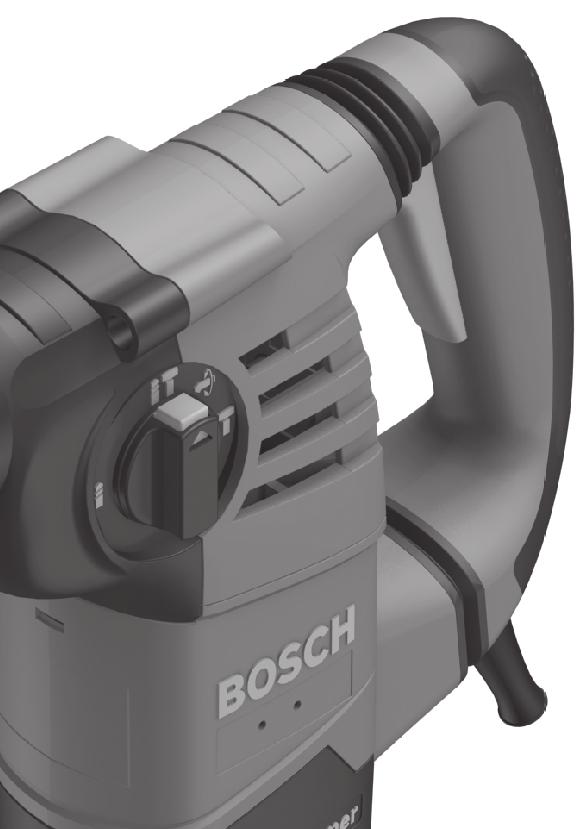
14 OBJ_BUCH book Page 27 Tuesday, April 7, :51 AM English 27 Operation Starting Operation Observe the mains voltage! The voltage of the power source must correspond with the data on the type plate of the machine. Setting the Operating Mode The operating mode of the power tool is selected with the mode selector switch 9. Note: Change the operating mode only when the machine is switched off! Otherwise, the machine can be damaged. To change the operating mode, push the release button 8 and turn the mode selector switch 9 to the requested position until it can be heard to latch. Position for hammer drilling in concrete or stone Position for drilling without impact in wood, metal, ceramic and plastic as well as for screwdriving Vario-Lock position for adjustment of the chiselling position The mode selector switch 9 does not latch in this position. Position for chiselling Reversing the Rotational Direction The rotational direction switch 13 is used to reverse the rotational direction of the machine. Actuate the rotational direction switch 13 only when the machine is at a standstill. Right rotation: Turn the rotational direction switch 13 to the stop in position. Left rotation: Turn the rotational direction switch 13 to the stop in position. Set the direction of rotation for hammer drilling, drilling and chiselling always to right rotation. Switching On and Off To start the machine, press the On/Off switch 7. To switch off the machine, release the On/Off switch 7. Setting the Speed/Impact Rate The speed/impact rate of the switched on power tool can be variably adjusted, depending on how far the On/Off switch 7 is pressed. Light pressure on the On/Off switch 7 results in low speed/impact rate. Further pressure on the switch increases the speed/impact rate. Safety Clutch If the tool insert becomes caught or jammed, the drive to the drill spindle is interrupted. Because of the forces that occur, always hold the power tool firmly with both hands and provide for a secure stance. If the power tool jams, switch the machine off and loosen the tool insert. When switching the machine on with the drilling tool jammed, high reaction torques can occur. Working Advice Changing the Chiselling Position (Vario-Lock) The chisel can be locked in 36 positions. In this manner, the optimum working position can be set for each application. Insert the chisel into the tool holder. Turn the mode selector switch 9 to the Vario- Lock position (see Setting the Operating Mode, page 27). Turn the tool holder to the desired chiselling position. Turn the mode selector switch 9 to the chiselling position. The tool holder is now locked. For chiselling, set the rotation direction to right rotation. Bosch Power Tools E56 (7.4.09)
15 OBJ_BUCH book Page 28 Tuesday, April 7, :51 AM 28 English Inserting Screwdriver Bits (see figure L) Apply the power tool to the screw/nut only when it is switched off. Rotating tool inserts can slip off. To work with screwdriver bits, a universal bit holder 27 with SDS-plus shank (accessory) is required. Clean the shank end of the adapter shank and apply a light coat of grease. Insert the universal bit holder with a turning motion into the tool holder until it automatically locks. Check the locking effect by pulling the universal bit holder. Insert a screwdriver bit into the universal bit holder. Use only screwdriver bits that match the screw head. Turn the mode selector switch 9 to the drilling position. To remove the universal bit holder, pull the locking sleeve 5 toward the rear and remove the universal bit holder 27 out of the tool holder. Maintenance and Service Maintenance and Cleaning Before any work on the machine itself, pull the mains plug. For safe and proper working, always keep the machine and ventilation slots clean. A damaged dust protection cap should be changed immediately. We recommend having this carried out by an after-sales service. Clean the tool holder 3 each time after using. If the machine should fail despite the care taken in manufacturing and testing procedures, repair should be carried out by an after-sales service centre for Bosch power tools. In all correspondence and spare parts order, please always include the 10-digit article number given on the type plate of the machine. After-sales Service and Customer Assistance Our after-sales service responds to your questions concerning maintenance and repair of your product as well as spare parts. Exploded views and information on spare parts can also be found under: Our customer consultants answer your questions concerning best buy, application and adjustment of products and accessories. Great Britain Robert Bosch Ltd. (B.S.C.) P.O. Box 98 Broadwater Park North Orbital Road Denham Uxbridge UB 9 5HJ Tel. Service: +44 (0844) Fax: +44 (0844) SPT-Technical.de@de.bosch.com Ireland Origo Ltd. Unit 23 Magna Drive Magna Business Park City West Dublin 24 Tel. Service: +353 (01) Fax: +353 (01) Australia, New Zealand and Pacific Islands Robert Bosch Australia Pty. Ltd. Power Tools Locked Bag 66 Clayton South VIC 3169 Customer Contact Center Inside Australia: Phone: +61 (01300) Fax: +61 (01300) Inside New Zealand: Phone: +64 (0800) Fax: +64 (0800) Outside AU and NZ: Phone: +61 (03) E56 (7.4.09) Bosch Power Tools
16 OBJ_BUCH book Page 29 Tuesday, April 7, :51 AM English 29 Republic of South Africa Customer service Hotline: +27 (011) Gauteng BSC Service Centre 35 Roper Street, New Centre Johannesburg Tel.: +27 (011) Fax: +27 (011) bsctools@icon.co.za KZN BSC Service Centre Unit E, Almar Centre 143 Crompton Street Pinetown Tel.: +27 (031) Fax: +27 (031) bsc.dur@za.bosch.com Western Cape BSC Service Centre Democracy Way, Prosperity Park Milnerton Tel.: +27 (021) Fax: +27 (021) bsc@zsd.co.za Bosch Headquarters Midrand, Gauteng Tel.: +27 (011) Fax: +27 (011) rbsa-hq.pts@za.bosch.com Disposal The machine, accessories and packaging should be sorted for environmental-friendly recycling. Only for EC countries: Do not dispose of power tools into household waste! According the European Guideline 2002/96/EC for Waste Electrical and Electronic Equipment and its implementation into national right, power tools that are no longer usable must be collected separately and disposed of in an environmentally correct manner. Subject to change without notice. Bosch Power Tools E56 (7.4.09)
GBH 5-40 DE Professional
 Robert Bosch GmbH Power Tools Division 70745 Leinfelden-Echterdingen www.bosch-pt.com GBH 5-40 DE Professional 1 619 929 720 (2007.08) O / 104 de Originalbetriebsanleitung en Original instructions fr Notice
SAFETY PRECAUTIONS SPECIFICATIONS
 SAFETY PRECAUTIONS Read the instructions carefully before use and save them for future reference. Before you connect the appliance: Ensure that the voltage rating on the type plate corresponds to your
Installation Instructions
 Installation Instructions (Cat. No. 1794-IE8 Series B) This module mounts on a 1794 terminal base unit. 1. Rotate keyswitch (1) on terminal base unit (2) clockwise to position 3 as required for this type
SAFETY PRECAUTIONS SPECIFICATIONS
 SAFETY PRECAUTIONS Read the instructions carefully before use and save them for future reference. Before you connect the appliance: Ensure that the voltage rating on the type plate corresponds to your
IMPORTANT! RETAIN FOR FUTURE REFERENCE PLEASE READ CAREFULLY VIKTIGT! BEHÅLL FÖR FRAMTIDA REFERENS LÄS IGENOM INSTRUKTIONSMANUALEN
 Heart & Stripes Junior Bed Instructions Manual Instruktions Manual IMPORTANT! RETAIN FOR FUTURE REFERENCE PLEASE READ CAREFULLY VIKTIGT! BEHÅLL FÖR FRAMTIDA REFERENS LÄS IGENOM INSTRUKTIONSMANUALEN Thank
ARC 32. Tvättställsblandare/Basin Mixer. inr.se
 ARC 32 Tvättställsblandare/Basin Mixer inr.se SE Användning och skötsel Manualen är en del av produkten. Bevara den under hela produktens livscykel. Vi rekommenderar er att noggrant läsa igenom manualen
SAFETY PRECAUTIONS SPECIFICATIONS
 SAFETY PRECAUTIONS Read the instructions carefully before use and save them for future reference. Before you connect the appliance: Ensure that the voltage rating on the type plate corresponds to your
GST Professional 14,4 V 18 V 24 V. Robert Bosch GmbH Power Tools Division Leinfelden-Echterdingen Germany.
 OBJ_DOKU-10647-00.fm Page 1 Tuesday, October 20, 2009 10:55 AM Robert Bosch GmbH Power Tools Division 70745 Leinfelden-Echterdingen Germany www.bosch-pt.com 2 609 92 701 (2009.10) O / 18 WEU GST Professional
81152 TRANSFER CASE SHIFT HANDLE
 Installation Instructions for TRANSFER CASE SHIFT HANDLE for 2007 2018 JEEP JK WRANGLER 1 2 3 ITEM NO. PART NO. DESCRIPTION QTY. 1 4101359 SHIFT KNOB, JEEP WRANGLER JK, MOLDED 1 2 1794720 JAM NUT, 3/8
INKOPPLINGSANVISNING ELTRYCKSLÅS WIRING DIAGRAM SOLENOID LOCK
 INKOPPLINGSANVISNING ELTRYCKSLÅS WIRING DIAGRAM SOLENOID LOCK SE EN S. 2-4 P. 5-7 SL 510/511 SL 520/521 SL 530-50/531-50 2013 11 07 SE TEKNISK SPECIFIKATION Driftspänning. Ström. Reed relä. Drifttemperatur.
IMPORTANT! RETAIN FOR FUTURE REFERENCE PLEASE READ CAREFULLY VIKTIGT! BEHÅLL FÖR FRAMTIDA REFERENSLÄS IGENOM INSTRUKTIONSMANUALEN NOGGRANT
 13060 Basic Cot One Instruction Manual Instruktion Manual IMPORTANT! RETAIN FOR FUTURE REFERENCE PLEASE READ CAREFULLY VIKTIGT! BEHÅLL FÖR FRAMTIDA REFERENSLÄS IGENOM INSTRUKTIONSMANUALEN NOGGRANT Thank
GSG 300 Professional. Robert Bosch GmbH Power Tools Division Leinfelden-Echterdingen Germany.
 OBJ_DOKU-868-004.fm Page 1 Wednesday, August 25, 2010 1:38 PM Robert Bosch GmbH Power Tools Division 70745 Leinfelden-Echterdingen Germany www.bosch-pt.com GSG 300 Professional 3 609 929 B97 (2010.08)
GSR 10,8-LI Professional
 OBJ_DOKU-17707-001.fm Page 1 Thursday, August 27, 2009 2:43 PM Robert Bosch GmbH Power Tools Division 70745 Leinfelden-Echterdingen Germany www.bosch-pt.com GSR 10,8-LI Professional 2 609 140 669 (2009.09)
BBT057/ BBC057 BBCD057/ BBT057-NL HOLDEN COLORADO 9/2016+ HOLDEN TRAILBLAZER WD & 4WD Models
 INSTALLATION GUIDE BBT057/ BBC057 BBCD057/ BBT057-NL HOLDEN COLORADO 9/2016+ HOLDEN TRAILBLAZER 2017+ 2WD & 4WD Models Ironman 4x4 BBT/ BBC/ BBCD/BBT057-NL Bull Bars fit to a Holden Colorado 9/2016+ It
Joki Joki Air. JCD70-xx JAD90-xx. lasiesta.com. Manual. Betriebsanleitung. Manuel. Manual. Manuale. Gebruiksaanwijzing.
 lasiesta.com LA SIESTA GmbH Im Wiesenweg 4 55270 Jugenheim Germany Tel: +49 6130 9119-19 LA SIESTA Inc. 7355 S.W. 87 th Ave., Ste. 100 Miami, FL 33173 USA Tel: +1 786 401-1138 EN DE FR ES IT NL DA SV FI
GDR GDS Professional 14,4 V-LI 18 V-LI. Robert Bosch GmbH Power Tools Division Leinfelden-Echterdingen Germany.
 OBJ_DOKU-14451-001.fm Page 1 Thursday, October 23, 2008 7:50 AM Robert Bosch GmbH Power Tools Division 70745 Leinfelden-Echterdingen Germany www.bosch-pt.com 2 609 140 600 (2008.10) O / 268 UNI GDR GDS
Isio. Robert Bosch GmbH Power Tools Division Leinfelden-Echterdingen Germany. F 016 L (2010.
 OBJ_DOKU-15498-002.fm Page 1 Friday, August 6, 2010 10:30 AM WEU WEU Robert Bosch GmbH Power Tools Division 70745 Leinfelden-Echterdingen Germany www.bosch-garden.com Isio F 016 L70 633 (2010.08) O / 163
Windlass Control Panel v1.0.1
 SIDE-POWER Windlass Systems 86-08950 Windlass Control Panel v1.0.1 EN Installation manual Behåll denna manual ombord! S Installations manual SLEIPNER AB Kilegatan 1 452 33 Strömstad Sverige Tel: +46 525
Multifunktions-Detector Multi detector
 Multifunktions-Detector Multi detector... 7 Numeric Display Low Battery Alert Wood Alternating Current Metal Sensor Range Metal Metal Object Sensor Range Alternating Current Battery Compartment Bar Graph-Display
SAFETY PRECAUTIONS SPECIFICATIONS
 SAFETY PRECAUTIONS Read the instructions carefully before use and save them for future reference. Before you connect the appliance: Ensure that the voltage rating on the type plate corresponds to your
AHS 48 LI 52 LI. Robert Bosch GmbH Power Tools Division Leinfelden-Echterdingen Germany.
 OBJ_DOKU-9003-006.fm Page 1 Monday, December 13, 2010 12:52 PM Robert Bosch GmbH Power Tools Division 70745 Leinfelden-Echterdingen Germany www.bosch-garden.com F 016 L70 729 (2010.12) O / 298 UNI AHS
Support Manual HoistLocatel Electronic Locks
 Support Manual HoistLocatel Electronic Locks 1. S70, Create a Terminating Card for Cards Terminating Card 2. Select the card you want to block, look among Card No. Then click on the single arrow pointing
BBT042/ BBC042/ BBCD042 NISSAN NAVARA D40 V STX & PATHFINDER R WD & 4WD Models
 INSTALLATION GUIDE BBT042/ BBC042/ BBCD042 NISSAN NAVARA D40 V6 2010+ STX & PATHFINDER R51 2010+ 2WD & 4WD Models Ironman 4x4 BBT/ BBC/ BBCD042 Bull Bars fit to a Nissan Navara D40 STX & Pathfinder R51.
LINC MODELL 13. INR SVERIGE AB Kosterögatan 15 SE-211 24 Malmö 13 EN 1428:2005+A1:2008
 LINC MODELL 13 151005 Produkten är anpassad till branschregler Säker Vatteninstallation. INR garanterar produktens funktion om branschreglerna och monteringsanvisningen följs. INR SVERIGE AB Kosterögatan
SVENSK STANDARD SS-ISO :2010/Amd 1:2010
 SVENSK STANDARD SS-ISO 14839-1:2010/Amd 1:2010 Fastställd/Approved: 2010-11-08 Publicerad/Published: 2010-11-30 Utgåva/Edition: 1 Språk/Language: engelska/english ICS: 01.040.17; 17.160 Vibration och stöt
DNM 60 L DNM 120 L PROFESSIONAL
 DNM 60 L DNM 120 L PROFESSIONAL Bedienungsanleitung Operating instructions Instructions d emploi Instrucciones de servicio Manual de instruções Istruzioni d uso Gebruiksaanwijzing Betjeningsvejledning
Boiler with heatpump / Värmepumpsberedare
 Boiler with heatpump / Värmepumpsberedare QUICK START GUIDE / SNABBSTART GUIDE More information and instruction videos on our homepage www.indol.se Mer information och instruktionsvideos på vår hemsida
Dokumentnamn Order and safety regulations for Hässleholms Kretsloppscenter. Godkänd/ansvarig Gunilla Holmberg. Kretsloppscenter
 1(5) The speed through the entire area is 30 km/h, unless otherwise indicated. Beware of crossing vehicles! Traffic signs, guardrails and exclusions shall be observed and followed. Smoking is prohibited
Instruction Manual. Svenska, English. Power Bank. Model: PRBN
 Instruction Manual Svenska, English Power Bank Model: PRBN Innehåll / Content Innehåll Säkerhetsföreskrifter... 4 Delar... 5 Specifikationer... 6 Miljö / Lag och säkerhet / Förbehåll... 7 Content Safety
VASSVIK FIXED STAND SE / ENG
 VASSVIK FIXED STAND SE / ENG SE VIKTIGT Läs noga igenom instruktionerna före användning och spar dessa för framtida bruk. VARNING: Barnets huvud bör inte ligga lägre än barnets kropp. Lägg inte till ytterligare
Rev No. Magnetic gripper 3
 Magnetic gripper 1 Magnetic gripper 2 Magnetic gripper 3 Magnetic gripper 4 Pneumatic switchable permanent magnet. A customized gripper designed to handle large objects in/out of press break/laser cutting
Nathi Skötbord Changing unit Table à langer murale Wickeltisch Verschoontafel Puslebord Cambiador de pared Přebalovací pult Fasciatoio
 Nathi Skötbord Changing unit Table à langer murale Wickeltisch Verschoontafel Puslebord Cambiador de pared Přebalovací pult Fasciatoio Пеленальный стол Tested and approved according to SS-EN 12221:2008+A1_2013
INSTALLATION INSTRUCTIONS
 INSTALLATION - REEIVER INSTALLATION INSTRUTIONS RT0 RF WIRELESS ROOM THERMOSTAT AND REEIVER MOUNTING OF WALL MOUTING PLATE - Unscrew the screws under the - Pack contains... Installation - Receiver... Mounting
LINC 23. Tvättställsblandare/Basin Mixer. inr.se 130226A
 LINC 23 Tvättställsblandare/Basin Mixer 130226A inr.se S Användande och skötsel Manualen är en del av produkten. Bevara den under hela produktens livscykel. Vi rekommenderar att noggrant läsa igenom manualen
Contents / Innehållsförteckning
 Contents / Innehållsförteckning Copyright This manual is the copyright of CI no 55650-4137. No part of this manual may be revised, copied or transmitted in any way without written permission from CI no
Robert Bosch GmbH ART F 016 L UNI
 OBJ_DOKU-8678-003.fm Page 1 Wednesday, October 27, 2010 3:55 PM Robert Bosch GmbH Power Tools Division 70745 Leinfelden-Echterdingen Germany www.bosch-garden.com F 016 L70 778 (2010.10) O / 298 UNI ART
LÄNKHJUL S3. Monteringsanvisning för: Länkhjul S3
 MONTERINGSANVISNING LÄNKHJUL S3 Art.no. 8822117 Rev.2018-01 Link to english Monteringsanvisning för: Länkhjul S3 art.nr. 2002010 Länkhjul S3 90 mm art.nr. 2002020 Länkhjul S3 120 mm art.nr. 2002030 Länkhjul
GCM 8 SJL Professional
 OBJ_BUCH-1736-002.book Page 1 Wednesday, October 31, 2012 3:55 PM Robert Bosch GmbH Power Tools Division 70745 Leinfelden-Echterdingen Germany www.bosch-pt.com GCM 8 SJL Professional 1 609 92A 04K (2012.11)
säkerhetsutrustning / SAFETY EQUIPMENT
 säkerhetsutrustning / SAFETY EQUIPMENT Hastighetsvakt / Speed monitor Kellves hastighetsvakter används för att stoppa bandtransportören när dess hastighet sjunker under beräknade minimihastigheten. Kellve
Monteringsanvisning Nödutrymningsbeslag ASSA 179E
 Monteringsanvisning Nödutrymningsbeslag ASSA 179E Denna monteringsanvisning avser nödutrymningsbeslag ASSA 179E med artikelnummer 364371 i kombination med låshus Abloy EL580 med artikelnummer EL580100011.
INSTRUCTION MANUAL SVENSKA / ENGLISH MULTISANDER MSP130
 INSTRUCTION MANUAL SVENSKA / ENGLISH MULTISANDER MSP130 INNEHÅLLSFÖRTECKNING / TABLE OF CONTENT SVENSKA Säkerhetsföreskrifter...4-7 Delar...8 Användning...9 Underhåll... 10 Specifikationer... 10 Information...11
Tekniska data Mutterdragare
 Tekniska data 91-250 Mutterdragare (GB) Technical data (S) Teknisk data Power supply: 230 V~/50 Hz Spänning: 230 V~/50 Hz Input power: 850 W Effekt: 850 W Speed: 2100 R.P.M. Varvtal: 2100 v/min Drive:
Users manual Bruksanvisning Gebrauchanweisung Guide d instructions
 Multi-pressure bucket pump Bärbar fettpump hochdruck abschmierpumpe distributeur manuel de graisse Users manual Bruksanvisning Gebrauchanweisung Guide d instructions 11018-1 - 815850 R02/03 IMPORTANT:
ORBITAL SANDER 7381 (F )
") ORBITAL SANDER 7381 (F0157381.. ) 6 ORIGINAL INSTRUCTIONS 8 NOTICE ORIGINALE 11 ORIGINALBETRIEBSANLEITUNG ORIGINELE GEBRUIKSAANWIJZING 20 ORIGINAL BRUGSANVISNING ORIGINAL BRUKSANVISNING ALKUPERÄISET OHJEET
ORBITAL SANDER 7381 (F0157381.. ) 6 ORIGINAL INSTRUCTIONS 8 NOTICE ORIGINALE 11 ORIGINALBETRIEBSANLEITUNG ORIGINELE GEBRUIKSAANWIJZING 20 ORIGINAL BRUGSANVISNING ORIGINAL BRUKSANVISNING ALKUPERÄISET OHJEET
Your No. 1 Workout. MANUAL pro
 Your No. 1 Workout MANUAL pro Innehåll/Contents Svenska Viktigt om säkerhet Specifikationer & delar Rekommenderade övningar 3 5 6-7 2 English Safety instructions Specifications & parts Recommended exercises
 BÄNKVÅG / BENCH SCALE Modell : SW-III / Model : SW-III ANVÄNDARMANUAL / USER MANUAL SW-III WWW.LIDEN-WEIGHING.SE 2014-03-26 OBS! Under vågen sitter en justerbar skruv (se bild). Standardinställning är
GWS Professional LVI LVI LVI LVI. Robert Bosch GmbH Power Tools Division Leinfelden-Echterdingen.
 OBJ_DOKU-7159-004.fm Page 1 Wednesday, June 4, 2008 11:25 AM Robert Bosch GmbH Power Tools Division 70745 Leinfelden-Echterdingen www.bosch-pt.com 1 609 929 L56 (2008.06) O / 372 UNI GWS Professional 22-180
Ringmaster RM3 - RM 5 RM3 RM 4 RM 5
 RM3 - RM 5 Ringmaster We offer ball pickers in 5 different sizes with a picking width of up to 6 m. RM3 - RM5 has a self-supporting chassis so that the collected balls do not place a load on the picking
Montageanvisning Airway system 1000/1500 Assembly instruction Airway system 1000/1500
 S.Det är lämpligt att denna information överlämnas till användaren av anläggningen. GB. It is appropriate that this information is passed on to the user of the installation. D. Diese informationen sind
INDUKTIV SLINGDETEKTOR INDUCTIVE LOOP DETECTOR
 INDUKTIV SLINGDETEKTOR INDUCTIVE LOOP DETECTOR Slingdetektorn används som ett alternativ till mekaniska gränslägen, momentbrytare eller annat gränsläge i gödselrännor. Detektorn är kopplad till en trådslinga
BBT014/ BBC014/ BBCD014 PJ & PK FORD RANGER WD & 4WD Models
 INSTALLATION GUIDE BBT014/ BBC014/ BBCD014 PJ & PK FORD RANGER 2007+ 2WD & 4WD Models Ironman 4x4 BBT/ BBC/ BBCD014 Bull Bars fit to a Ford Ranger. It will take about 3 hours to install. NOTE: This product
Plain A262. För T16 (T5) lysrör. Innehåll. Monteringsanvisning. A. Instruktion för rampmontering
 lysrör. Innehåll. Monteringsanvisning. A. Instruktion för rampmontering") Plain A262 För T16 (T5) lysrör Innehåll Ramparmatur: ändmodul En stängd gavel/ en öppen gavel Plint i båda ändarna Överkopplingssladd 1 rampgavel 1 lysrörsbytare Ramparmatur: mellanmodul Plint i en ände
Plain A262 För T16 (T5) lysrör Innehåll Ramparmatur: ändmodul En stängd gavel/ en öppen gavel Plint i båda ändarna Överkopplingssladd 1 rampgavel 1 lysrörsbytare Ramparmatur: mellanmodul Plint i en ände
FORTA M315. Installation. 218 mm.
 1 Installation 2 1 2 1 218 mm. 1 2 4 5 6 7 8 9 2 G, G0= Max 100 m 1.5 mm² (AWG 15) X1, MX, Y, VH, VC = Max 200 m 0.5 mm² (AWG 20) Y X1 MX VH VC G1 G0 G 0 V 24 V~ IN 0-10 0-5, 2-6 60 s OP O 1 2 4 5 6 7
Diskant Yta eller Vikelfäste montering Mount
 Installation och Bruksanvisning Inledning Välj fästpunkterna för dina dome TW250 Silk diskanter. Kom ihåg att för bästa prestanda bör diskanterna monteras så nära mitten av bas som möjligt, med fri, direkt
 BÄNKVÅG / BENCH SCALE ANVÄNDARMANUAL / USER MANUAL SW-III www.liden-weighing.com Svenska OBS! Under vågen sitter en justerbar skruv (se bild). Standardinställning är den för vägning. Om ni vill rengöra
BEAM. Product Manual Produktmanual
 BEAM Product Manual Produktmanual BEAM Technical Specifications Tekniska Specifikationer Description Product number Mode Voltage Current Vehicle interface Cable length Encapsulation Operating temperature
BATH MIXER 160 LINC 21. incl. HAND SHOWER. inr.se
 LINC 21 BATH MIXER 150 BATH MIXER 160 incl. HAND SHOWER 110309 inr.se Innan montering Vi förordar en sakkunnig VVS-installatör vid installation och service. Ledningarna ska renspolas innan installation.
USER INSTRUCTIONS. Smart-Splitter A Smart-Line Product
 USER INSTRUCTIONS BRUKSANVISNING I ORIGINAL. USER INSTRUCTIONS IN ORIGINAL FORMAT. ARTIKELNR. / ARTICLE NO: 0458-395-2800 Smart-Splitter A Smart-Line Product Patented 1 2 Greppyta Grip area 10 3 4 5 6
Bathtub Filler CN EN. TBP02201 Type / TBP02202 Type. Installation Manual. Continued on the back cover
 03N74E Installation Manual 207.8 Bathtub Filler TBP0220 Type / TBP02202 Type For best results, install the product correctly according to the instructions in this Installation Manual. After installation,
P650 - Takscreen. Installationsguide EN
 P650 - Takscreen Installationsguide 1309-150507EN V650-Tallinn Installation manual Montera främre linhjul 12 13 Placera linan över linhjulet och skruva tillbaka täcklocket på linhjulhuset (7). Öppna linhjulshuset
LINC Modell 17 130624A
 LINC Modell 17 130624A Denna produkt är anpassad till Branschregler Säker Vatteninstallation. INR garanterar produktens funktion om branschregler och monteringsanvisning följs. INR SVERIGE AB Kosterögatan
Beijer Electronics AB 2000, MA00336A, 2000-12
 Demonstration driver English Svenska Beijer Electronics AB 2000, MA00336A, 2000-12 Beijer Electronics AB reserves the right to change information in this manual without prior notice. All examples in this
ASSEMBLY INSTRUCTIONS SCALE - SYSTEM
 ASSEMBLY INSTRUCTIONS 60 mm 00 mm 600 mm 000 mm R50 mm ALL COMPONENTS Metal profile 60 mm (start and end of system) Metal profile connection Wire Felt square Metal profile 00 mm Metal profile connection
UV-C TECH 16 WATT 40 WATT 75 WATT 130 WATT AMALGAM. UV-C and Pool equipment MEMBER OF:
 UV-C TECH UV-C and Pool equipment 16 WATT 40 WATT 75 WATT 130 WATT AMALGAM MEMBER OF: 2 BLUE LAGOON UV-C TECH UV-C and Pool equipment MANUAL BLUE LAGOON UV-C TECH BLUE LAGOON UV-C TECH EN 6-8 BLUE LAGOON
Industri-Vågar WEIGHING TENSIOMETER MODEL WT12 SERVICE ELLER KALIBRERING RING
 Industri-Vågar WEIGHING TENSIOMETER MODEL WT12 SERVICE ELLER KALIBRERING RING 040-984200 The WF12 can be rigged in any position to satisfy any loading condition: suspended weights, inserted in tensioned
Viktig information för transmittrar med option /A1 Gold-Plated Diaphragm
 Viktig information för transmittrar med option /A1 Gold-Plated Diaphragm Guldplätering kan aldrig helt stoppa genomträngningen av vätgas, men den får processen att gå långsammare. En tjock guldplätering
Information technology Open Document Format for Office Applications (OpenDocument) v1.0 (ISO/IEC 26300:2006, IDT) SWEDISH STANDARDS INSTITUTE
 v1.0 (ISO/IEC 26300:2006, IDT) SWEDISH STANDARDS INSTITUTE") SVENSK STANDARD SS-ISO/IEC 26300:2008 Fastställd/Approved: 2008-06-17 Publicerad/Published: 2008-08-04 Utgåva/Edition: 1 Språk/Language: engelska/english ICS: 35.240.30 Information technology Open Document
SVENSK STANDARD SS-ISO/IEC 26300:2008 Fastställd/Approved: 2008-06-17 Publicerad/Published: 2008-08-04 Utgåva/Edition: 1 Språk/Language: engelska/english ICS: 35.240.30 Information technology Open Document
STANDARD. UTM Ingegerd Annergren UTMS Lina Orbéus. UTMD Anders Johansson UTMS Jan Sandberg
 1(7) Distribution: Scania, Supplier Presskruvar med rundat huvud - Metrisk gänga med grov delning Innehåll Sida Orientering... 1 Ändringar från föregående utgåva... 1 1 Material och hållfasthet... 1 2
Active Speaker System X-Line 50 AW
 Active Speaker System X-Line 50 AW Important Safety Information: Read all documentation before operating your equipment. Retain all documentation for future reference. Save the carton and packing material
BBT034/ BBC034/ BBCD034 BBCD060/ BBT060-NL/ BB060-TL/ BB060-SL VOLKSWAGEN AMAROK
 INSTALLATION GUIDE BBT034/ BBC034/ BBCD034 BBCD060/ BBT060-NL/ BB060-TL/ BB060-SL VOLKSWAGEN AMAROK Ironman 4x4 BBT/ BBC/ BBCD034 BBCD060/ BBT060-NL/ BB060-TL/ BB060-SL Bull Bars fit to a Volkswagen Amarok.
ASSEMBLY INSTRUCTIONS SCALE SQUARE - STANDARD
 ASSEMBLY INSTRUCTIONS ALL COMPONENTS Metal profile 0 mm Gripper Ceiling attachments Screws for ceiling attachements (not included) Wires Metal profile 60 mm Metal profile 00 mm Felt - Full Felt - Half
MCP-16RC, Air Purification
 Kompakt patronfilter med tryckstötsrensning. MCP-16RC Air Purification Tower är ett kompakt patronfilter för decentraliserad luftrening inomhus, där luft återåtervinning är möjlig. Den kompakta filterenheten
Preschool Kindergarten
 Preschool Kindergarten Objectives CCSS Reading: Foundational Skills RF.K.1.D: Recognize and name all upper- and lowercase letters of the alphabet. RF.K.3.A: Demonstrate basic knowledge of one-toone letter-sound
Bruksanvisning Directions for use
 Bruksanvisning Directions for use KOMBIDON OUTSIDE WALL HOOD SVENSK/ENGLISH VERSION SVENSKA Denna montageanvisning omfattar produkten KOMBIDON. BESKRIVNING/ ANVÄNDNING Kombidon från AB C.A. Östberg är
Installation Instructions
 Installation Instructions (Catalog Number 1771-IL Series D) Use this document as a guide when installing the catalog number 1771-IL/D analog input module. The isolated analog input module is sensitive
ASSEMBLY INSTRUCTIONS SCALE CIRCLE - STANDARD
 ASSEMBLY INSTRUCTIONS ALL COMPONENTS Metal profile 0 mm Gripper Ceiling attachments Screws for ceiling attachements (not included) Wires Metal profile 60 mm Metal profile 00 mm Felt - Full Felt - Half
Om oss DET PERFEKTA KOMPLEMENTET THE PERFECT COMPLETION 04 EN BINZ ÄR PRECIS SÅ BRA SOM DU FÖRVÄNTAR DIG A BINZ IS JUST AS GOOD AS YOU THINK 05
 Om oss Vi på Binz är glada att du är intresserad av vårt support-system för begravningsbilar. Sedan mer än 75 år tillverkar vi specialfordon i Lorch för de flesta olika användningsändamål, och detta enligt
RADIATION TEST REPORT. GAMMA: 30.45k, 59.05k, 118.8k/TM1019 Condition D
 RADIATION TEST REPORT PRODUCT: OP47AYQMLL Die Type: 147X FILE: OP47_LDR.xlsx DATE CODE: 95 GAMMA: 3.45k, 59.5k, 118.8k/TM119 Condition D GAMMA SOURCE: Co6 DOSE RATE: 8.6mRad(si)/s FACILITIES: University
 INSTALLATION INSTRUCTIONS Accessory S P/N 08E12-SZT-100 Application CR-Z Publications No. Issue Date SEP PARTS LIST Left illuminated door sill trim Right illuminated door sill trim Illumination harness
Montageanvisning Airway system 1000/1500 Assembly instruction Airway system 1000/1500
 S.Det är lämpligt att denna information överlämnas till användaren av anläggningen. GB. It is appropriate that this information is passed on to the user of the installation. D. Diese informationen sind
SkillGuide. Bruksanvisning. Svenska
 SkillGuide Bruksanvisning Svenska SkillGuide SkillGuide är en apparat utformad för att ge summativ återkoppling i realtid om hjärt- och lungräddning. www.laerdal.com Medföljande delar SkillGuide och bruksanvisning.
CompactAIR Center Ventilation - Filtrering - Uppvärmning CompactAIR Center Ventilation - Filtration - Heating
 CompactAIR / CompactAIR CompactAIR Center Ventilation - Filtrering - Uppvärmning CompactAIR Center Ventilation - Filtration - Heating Typenschlüssel / Type Code Beteckning / Type code Compact AIR / CompactAIR
VARIOBARRIER S/M MIMSAFE BY CHOICE
 VAROBARRR S/M MMSA BY CHOC K L A B D M C H A B C D 522 K 524 Right leg Right leg 514L 514R 510L 510R L 526L M 526R S508 S509 521 6X 521 + H 527 529 528 8X/1 18X 8X/1 M-460641AL M-SM6X14A M-460641B M-M37202_2014
PFC and EMI filtering
 PFC and EMI filtering Alex Snijder Field Application Engineer Wurth Elektronik Nederland B.V. November 2017 EMC Standards Power Factor Correction Conducted emissions Radiated emissions 2 Overview of standard
Digital Personvåg MANUAL H
 Digital Personvåg MANUAL H151-00-1 www. Specifikationer Kapacitet & Noggrannhet Strömförsörjning Arbetsmiljö 250kg / 0.1kg Adapter 120VAC-9VDC-50Hz / 230VAC 9VDC 50Hz Arbetstemperatur: 10 C to 35 C Förvaring,
BBT034/ BBC034/ BBCD034 VOLKSWAGEN AMAROK. Ironman 4x4 BBT/ BBC/ BBCD034 Bull Bars fit to a Volkswagen Amarok. It will take about 3 hours to install.
 INSTALLATION GUIDE BBT034/ BBC034/ BBCD034 VOLKSWAGEN AMAROK Ironman 4x4 BBT/ BBC/ BBCD034 Bull Bars fit to a Volkswagen Amarok. It will take about 3 hours to install. IMPORTANT - If your vehicle has front
Monteringsanvisning Podie T 4100 K
 Monteringsanvisning Podie T 4100 K Monteringsanvisning Förbered fundamentet 1. Montera ställfötterna. Montera tvättmaskin SV 1. Fäst gaffelbeslagen i bakkant med brickor och skruv. OBS! Placera beslagen
manual Facial spa Art nr: 48682 Rubicson 2016-06-08
 manual Facial spa Art nr: 8682 EN NO SV 2016-06-08 Rubicson ENGLISH Overview Use Fill the container ENGLISH 1. Make sure that the power cord is not connected to a wall socket. 1 2 2. Remove the funnel
Får endast utföras av behörig personal. May only be carried out by authorized electrician
 Instruktion för DMIS Instruction for DMIS FLE400FC, FLE850MP, W3400H, W4400H/W4600H (-980/1287) W3850H/W31100H, W4850/W41100H (-1220/636) Clarus Control 471 1530-75 2016.05.04 Får endast utföras av behörig
Installation. Twice Nisch. Twice Corner SVENSKA ENGLISH
 Installation Arrow Skandinavien AB Tel: +46 (0)31 330 00 10 www.arrowshower.com Twice Corner Twice Nisch SVENSKA (SV) Installationsanvisning för Arrow duschvägg. Vi förbättrar ständigt våra installationsanvisningar.
VASSVIK ROCKING STAND
 VASSVIK ROCKING STAND SE / ENG SE VIKTIGT Läs noga igenom instruktionerna före användning och spar dessa för framtida bruk. VARNING: Barnets huvud bör inte ligga lägre än barnets kropp. Lägg inte till
Användarhandbok. USB Charging Dock DK52
 Användarhandbok USB Charging Dock DK52 Innehåll Inledning...3 Om DK52 USB Charging Dock...3 Använda DK52 USB Charging Dock...4 Använda tillbehören...4 Ladda...4 Juridisk information...6 Declaration of
Lösenordsportalen Hosted by UNIT4 For instructions in English, see further down in this document
 Lösenordsportalen Hosted by UNIT4 For instructions in English, see further down in this document Användarhandledning inloggning Logga in Gå till denna webbsida för att logga in: http://csportal.u4a.se/
KTH MMK JH TENTAMEN I HYDRAULIK OCH PNEUMATIK allmän kurs 2006-12-18 kl 09.00 13.00
 KTH MMK JH TENTAMEN I HYDRAULIK OCH PNEUMATIK allmän kurs 2006-12-18 kl 09.00 13.00 Svaren skall vara läsligt skrivna och så uppställda att lösningen går att följa. När du börjar på en ny uppgift - tag
Isolda Purchase - EDI
 Isolda Purchase - EDI Document v 1.0 1 Table of Contents Table of Contents... 2 1 Introduction... 3 1.1 What is EDI?... 4 1.2 Sending and receiving documents... 4 1.3 File format... 4 1.3.1 XML (language
PRESS FÄLLKONSTRUKTION FOLDING INSTRUCTIONS
 PRESS FÄLLKONSTRUKTION FOLDING INSTRUCTIONS Vänd bordet upp och ner eller ställ det på långsidan. Tryck ner vid PRESS och fäll benen samtidigt. OBS! INGA STORA KRAFTER KRÄVS!! Om benen sitter i spänn tryck
FLUID SOLUTIONS 700ZDT & 700NDT. NAMUR Solenoid Valve 3/2 5/2 INSTALLATION, OPERATION & MAINTENANCE MANUAL. JWB USA, Inc. TUNING FLUID SOLUTIONS
 700ZDT & 700NDT NAMUR Solenoid Valve 3/2 5/2 INSTALLATION, OPERATION & MAINTENANCE MANUAL TUNING JWB USA, Inc. Table of content TABLE OF CONTENTS CHAPTER 1: PRODUCT DESCRIPTION 1 CHAPTER 2: METHOD of OPERATION
Användarhandbok. MHL to HDMI Adapter IM750
 Användarhandbok MHL to HDMI Adapter IM750 Innehåll Inledning...3 MHL to HDMI Adapter-översikt...3 Komma igång...4 Smart Connect...4 Uppgradera Smart Connect...4 Använda MHL to HDMI Adapter...5 Ansluta
Installation Instruction Monteringsinstruktion JK400
 Installation Instruction Monteringsinstruktion JK400 Tools: 2pcs of spanner 13 and 17mm or 2pcs of adjustable spanner, cross slotted screwdriver PZ 2 Warning: Plates can be sharp in the edges and corners,
Monteringsanvisning benfundament TM 8055, TM 8060, T 8118 K. Art nr ,
 Monteringsanvisning benfundament TM 8055, TM 8060, T 8118 K Art nr 102056, 102057 Monteringsanvisning Förbered fundamentet 1. Montera ställfötterna. Montera tvättmaskin SV 1. Fäst gaffelbeslagen i bakkant