Beta 1934MAV 1934MAV70. Manuale d'uso ed istruzioni. Operation manual and instructions. Notice d'utilisation et instructions. Gebruikshandleiding
|
|
|
- Margareta Hansson
- för 6 år sedan
- Visningar:
Transkript
1 Beta 1934MAV 1934MAV70 I GB F NL D E P S SF DK N H TR PL Manuale d'uso ed istruzioni Operation manual and instructions Notice d'utilisation et instructions Gebruikshandleiding Bedienungsanleitung Manual de uso e instrucciones Manual de uso e instruções Bruksanvisning Käyttöohjeet Brugsmanual Bruksveiledning Használati kézikönyv és útmutató Kullanım ve Talimat Kılavuzu Instrukcja obsługi i zalecenia


2 Beta 1934MAV MAV70 ➀ ➁ ➂ ➃ ➄
3 Beta I MANUALE D USO ED ISTRUZIONI PER MICROSMERIGLIATRICI ASSIALI PRODOTTI DA: BETA UTENSILI S.P.A. Via A. Volta 18, 20845, Sovico (MB) ITALIA Documentazione redatta originariamente in lingua ITALIANA. ATTENZIONE IMPORTANTE LEGGERE COMPLETAMENTE IL PRESENTE MANUALE PRIMA DI UTILIZZARE L UTENSILE PNEUMATICO. IN CASO DI MANCATO RISPETTO DELLE NORME DI SICUREZZA E DELLE ISTRUZIONI OPERATIVE, POSSONO VERIFICARSI SERI INFORTUNI. Conservare accuratamente le istruzioni di sicurezza e consegnarle al personale utilizzatore. DESTINAZIONE D USO La microsmerigliatrice assiale pneumatica è destinata al seguente uso: levigare superfici asportare bave e/o residui di lavorazione è possibile l impiego della microsmerigliatrice anche in luoghi aperti esposti ad acqua e aria Non sono consentite le seguenti operazioni: è vietato l utilizzo di mole o dispositivi analoghi con diametro superiore a 50 mm è vietato l uso di mole a disco da taglio o frese è vietato l uso in ambienti contenenti atmosfere potenzialmente esplosive SICUREZZA DELLA POSTAZIONE DI LAVORO Prestare attenzione alle superfici che possono diventare scivolose a causa dell uso della macchina ed al pericolo di inciampamento nel tubo flessibile dell aria. Durante l utilizzo dell utensile pneumatico per lavori eseguiti in quota, adottare tutte le misure preventive atte ad eliminare o minimizzare i rischi ad altri lavoratori conseguenti a cadute accidentali dell attrezzatura (per esempio mediante segregazione dell area di lavoro, adeguata segnalazione, etc.). Non utilizzare l utensile pneumatico in ambienti contenenti atmosfere potenzialmente esplosive perché possono svilupparsi scintille in grado di incendiare polveri o vapori. Evitare il contatto con apparecchiature in tensione in quanto l utensile pneumatico non è isolato. Il contatto con elementi in tensione può causare una scossa elettrica. Al fine di rilevare linee di alimentazione nascoste, utilizzare idonee apparecchiature di ricerca oppure rivolgersi alla locale società erogatrice. Un contatto con linee elettriche può provocare lo sviluppo di incendi e di scosse elettriche. Danneggiando le linee del gas si crea il pericolo di esplosioni. Penetrando una tubazione dell acqua si provocano seri danni materiali. Impedire che bambini o visitatori possano avvicinarsi alla postazione di lavoro mentre si sta operando con l utensile pneumatico. La presenza di altre persone provoca distrazione che può comportare la perdita del controllo sull utensile pneumatico. SICUREZZA DEGLI UTENSILI PNEUMATICI Non puntare mai il flusso d aria verso se stessi o verso altre persone. L aria compressa può causare lesioni serie. Controllare i raccordi di collegamento e le tubazioni di alimentazione. Tutti i gruppi, i giunti e i tubi flessibili devono essere installati conformemente ai dati tecnici relativi alla pressione e al flusso d aria. Una pressione troppo bassa pregiudica il funzionamento dell utensile pneumatico; una pressione alta può causare danni e/o lesioni. Evitare di piegare o stringere i tubi flessibili. Evitare l uso di solventi e di spigoli taglienti. Proteggere i tubi da calore, olio e parti rotanti. Sostituire immediatamente un tubo flessibile danneggiato. Una tubazione di alimentazione difettosa può provocare movimenti incontrollati del tubo dell aria compressa. Polveri oppure trucioli sollevati dall aria possono provocare lesioni agli occhi. Accertarsi che le fascette per tubi flessibili siano sempre ben fissate.
4 INDICAZIONE PER LA SICUREZZA DEL PERSONALE Si raccomanda la massima attenzione avendo cura di concentrarsi sempre sulle proprie azioni. Non utilizzare l utensile pneumatico in caso di stanchezza o sotto l effetto di droghe, bevande alcoliche o medicinali. Utilizzare sempre i seguenti dispositivi individuali di protezione: occhiali di protezione scarpe di sicurezza otoprotettori guanti di protezione per agenti fisici guanti antivibrazione, da utilizzare a seguito di specifica analisi del livello di esposizione giornaliera alle vibrazioni per sistema mano-braccio Avere cura di mettersi in posizione sicura mantenendo l equilibrio in ogni momento. Una posizione di lavoro sicura ed un adatta postura del corpo permettono di poter controllare meglio l utensile pneumatico in caso di situazioni inaspettate. Non indossare vestiti larghi. Non portare bracciali e catenine. Tenere capelli, vestiti e guanti lontano da parti in movimento. Vestiti larghi, gioielli o capelli lunghi possono impigliarsi nelle parti in movimento. Non respirare direttamente l aria di scarico, evitando che possa arrivare agli occhi. L aria di scarico dell utensile pneumatico può contenere acqua, olio, particelle metalliche ed impurità. Questi elementi possono provocare pericoli. Non appoggiare mai la microsmerigliatrice prima che la mola sia completamente arrestata. UTILIZZO ACCURATO DELLA MICROSMERIGLIATRICE ASSIALE Per bloccare e supportare il pezzo in lavorazione utilizzare dispositivi di serraggio oppure morse. Non tenere il pezzo in lavorazione con una mano o bloccato con il corpo: così facendo non è più possibile operare in sicurezza. Non sottoporre l utensile pneumatico a sovraccarico. Effettuare i propri lavori utilizzando l utensile pneumatico esclusivamente per i casi previsti. Verificare sempre l integrità della macchina. Non utilizzare alcun utensile pneumatico il cui interruttore di avvio/arresto sia difettoso. Un utensile pneumatico che non può più essere arrestato o avviato è pericoloso e deve essere riparato. Interrompere sempre l alimentazione dell aria prima di effettuare operazioni di regolazione sulla microsmerigliatrice, prima di sostituire accessori oppure nel caso in cui lo stesso non venga utilizzato. Questa misura preventiva impedisce l avvio accidentale dell utensile pneumatico. Togliere gli utensili di regolazione prima dell utilizzo della microsmerigliatrice in quanto possono essere proiettati ad elevata velocità. Quando gli utensili pneumatici non vengono utilizzati, conservarli al di fuori del raggio di accesso dei bambini. Non permettere di usare l utensile pneumatico a persone che non abbiano letto le presenti istruzioni. Effettuare accuratamente la verifica dell utensile pneumatico accertandosi che le parti mobili dell utensile funzionino perfettamente, non si inceppino e non vi siano pezzi rotti o danneggiati al punto da pregiudicarne il funzionamento. Far riparare le parti danneggiate prima dell impiego dell utensile pneumatico. Controllare che la microsmerigliatrice sia in buone condizioni. Accertarsi che l albero e le relative filettature non siano danneggiate o usurate. Prima di ogni utilizzo verificare che la mola sia in buone condizioni, sia idonea al tipo di lavorazione da eseguire, non presenti danneggiamenti, scheggiature, crepe, etc. Accertarsi che il numero di giri indicato sulla mola abrasiva (o sulla sua confezione) sia uguale o superiore a quello indicato sulla microsmerigliatrice. Accertarsi che non siano presenti altre persone nelle vicinanze. Verificare periodicamente che la velocità della microsmerigliatrice non sia maggiore di quella indicata dal fornitore. Questa verifica deve essere eseguita senza montaggio della mola. Al momento dell arresto porre la microsmerigliatrice in una posizione stabile e sicura. L arresto della mola non è immediato. Utilizzare esclusivamente mole idonee per l attività prevista, come ad esempio: mole per levigare superfici mole per asportare bave e/o residui di lavorazione La microsmerigliatrice pneumatica non deve essere modificata. Le modifiche possono ridurre l efficacia delle misure di sicurezza ed aumentare i rischi per l operatore. Far riparare la microsmerigliatrice pneumatica solo ed esclusivamente da personale specializzato. Utilizzare pezzi di ricambio originali.
5 INDICAZIONI DI SICUREZZA PER LA MICROSMERIGLIATRICE ASSIALE Controllare che la targhetta di identificazione sia leggibile: eventualmente procurarsi dal produttore la targhetta per la sostituzione. La microsmerigliatrice pneumatica si può fermare se: viene sovraccaricata. Nel caso di bloccaggio della mola, arrestare immediatamente la microsmerigliatrice, mantenendola inattiva fino al completo sbloccaggio della mola stessa. Non tentare di estrarre la mola ancora in funzione. Prima di riprendere qualsiasi attività verificare che la mola sia fissata correttamente e non sia danneggiata. Possono essere scagliati dei pezzi ad elevata velocità nel caso di rottura del pezzo in lavorazione o della mola. Fare molta attenzione alle scintille di smerigliatura in quanto possono essere fonte di potenziali pericoli sia per le cose che per le persone che ne sono esposte. Possono incendiare indumenti e provocare ustioni. L operatore ed il personale addetto alla manutenzione devono essere in grado di gestire fisicamente il peso e la potenza dell utensile pneumatico. E importante essere preparati a movimenti inaspettati della microsmerigliatrice causati dal bloccaggio o dalla rottura della mola. Tenere sempre ben salda la microsmerigliatrice e portare il proprio corpo e le proprie braccia in una posizione che permetta di compensare questi movimenti. Non avvicinare mai la mano alla mola: ci si può ferire. Controllare periodicamente che la velocità della microsmerigliatrice non sia maggiore di quella indicata. Arrestare l utensile in caso di interruzione dell alimentazione dell aria oppure di una pressione di esercizio ridotta. Controllare la pressione d esercizio e, a pressione d esercizio ottimale, avviare di nuovo. Durante l utilizzo dell utensile pneumatico è possibile che l operatore provi sensazioni fastidiose a mani, braccia, spalle e nell area del collo. Assumere una posizione comoda cambiando la postura può aiutare ad evitare fastidi ed affaticamento. Prestare attenzione nel caso di funzionamento prolungato dell utensile pneumatico: parte dell utensile stesso e l accessorio possono diventare caldi. Utilizzare idonei guanti di protezione per agenti fisici. Pericoli dovuti a polveri e fumi: in funzione della tipologia del materiale lavorato, i fumi generati durante l utilizzo dell utensile pneumatico possono causare patologie alla salute delle persone. E necessaria un adeguata indagine di igiene ambientale per stabilire l esatta assegnazione del tipo e del grado di protezione dello specifico dispositivo di protezione individuale da utilizzare per le vie respiratorie. Durante l utilizzo dell utensile pneumatico sul pezzo da lavorare si generano rumori, a volte anche nocivi, per il personale esposto. E necessaria un adeguata indagine fonometrica per stabilire l esatta assegnazione dello specifico dispositivo di protezione individuale dell udito (otoprotettore) da utilizzare. Se da specifica indagine eseguita risulta che l esposizione giornaliera alle vibrazioni generata durante l utilizzo dell utensile pneumatico supera il valore limite di azione prevista dalla normativa vigente nel rispettivo paese, si devono utilizzare specifici guanti antivibrazione. Qualora doveste accorgervi che la pelle delle dita diventa intorpidita, oppure bianca, presenta formicolio o dolore, sospendere il lavoro con l utensile pneumatico. Informare il datore di lavoro e consultare un medico. Non far sobbalzare la mola sul pezzo in lavorazione: questo può causare un aumento sensibile delle vibrazioni. Tenere l utensile pneumatico con una presa sicura ma non eccessivamente salda, considerando le necessarie forze di reazione della mano. Non trasportatore mai l utensile pneumatico tenendolo per il tubo flessibile.
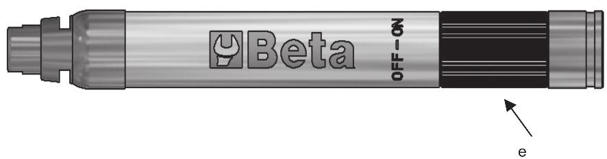
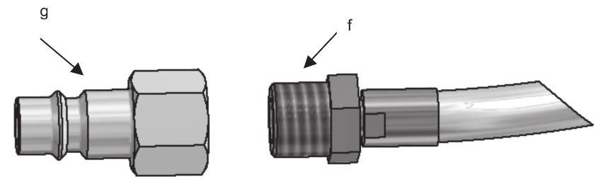
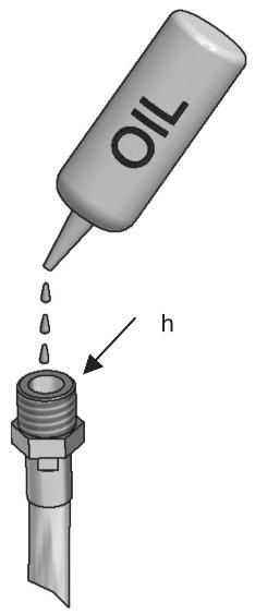
6 DISPOSITIVI DI PROTEZIONE INDIVIDUALI PREVISTI DURANTE L UTILIZZO DELL UTENSILE PNEUMATICO La mancata osservanza delle seguenti avvertenze può causare lesioni fisiche e/o patologie. NDOSSARE SEMPRE DISPOSITIVI OTOPROTETTORI QUANDO SI ADOPERA L UTENSILE PNEUMATICO INDOSSARE SEMPRE GLI OCCHIALI PROTETTIVI QUANDO SI ADOPERA L UTENSILE PNEUMATICO O QUANDO SI ESEGUE L ATTIVITÀ DI MANUTENZIONE UTILIZZARE SEMPRE GUANTI DI PROTEZIONE PER AGENTI FISICI DURANTE L UTILIZZO DELL UTENSILE PNEUMATICO UTILIZZARE SEMPRE CALZATURE DI SICUREZZA Ulteriori dispositivi di protezione individuali da utilizzare in funzione dei valori riscontrati nell indagine di igiene ambientale/analisi rischi nell eventualità che i valori superino i limiti previsti dalle vigenti normative. UTILIZZARE GUANTI ANTIVIBRAZIONE DURANTE L UTILIZZO DELL UTENSILE PNEUMATICO A SEGUITO DI SPECIFICA ANALISI DEL LIVELLO DI ESPOSIZIONE GIORNALIERA ALLE VIBRAZIONI PER SISTEMA MANO-BRACCIO UTILIZZARE MASCHERA DI PROTEZIONE PER AGENTI FISICI IN FUNZIONE DEL RISULTATO DI IGIENE AMBIENTALE UTILIZZARE CASCO DI PROTEZIONE DATI TECNICI 1934MAV 1934MAV70 VELOCITÀ A VUOTO giri/min giri/min CAPACITÀ PINZA Ø3 mm Ø3 mm POTENZA 0.04 kw 0.08 kw ATTACCO ARIA 1/4 GAS 1/4 GASr PRESSIONE MASSIMA 6.2 Bar 6.2 Bar DIAMETRO INT. MINIMO TUBO ARIA 4.5 mm 4.5 mm CONSUMO D DARIA MEDIO 115 l/min 115 l/min PESO 200 g 210 g LUNGHEZZA TOTALE 150 mm 150 mm LUNGHEZZA TUBO 1.5 m 1.5 m LIVELLO PRESSIONE SONORA 71.0 db(a) (EN ISO 15744) 80.0 db(a) (EN ISO 15744) LIVELLO POTENZA ACUSTICA 76.0 db(a) (EN ISO 15744) 87.0 db(a) (EN ISO 15744) LIVELLO VIBRAZIONI 2.5 m/s 2 (ISO ) 4 m/s 2 (ISO ) LEGENDA a: albero rotazione mola e: comando azionamento smerigliatrice b: protezione tubo con scarico aria f: attacco aria c: chiave a forchetta g: raccordo attacco aria 1/4 GAS d: mola h: lubrificazione olio ISTRUZIONI Collegamento alimentazione dell aria Per un utilizzo corretto dell utensile pneumatico rispettare sempre la pressione massima di 6.2 bar, misurata all ingresso dell utensile. Alimentare l utensile pneumatico con aria pulita e priva di condensa (immagine 4). Una pressione troppo elevata o la presenza di umidità nell aria di alimentazione riducono la durata delle parti meccaniche e possono causare danni all utensile..
7 UTILIZZO Avviamento / Arresto Per avviare la microsmerigliatrice ruotare il comando di azionamento e posizionarlo su ON (immagine 3-e). Al termine del lavoro riposizionare il comando sulla posizione OFF. La microsmerigliatrice si arresta in un tempo inferiore a 5s. La microsmerigliatrice è dotata di scarico dell aria posteriore attraverso la protezione del tubo (immagine 1-b). Al momento dell arresto porre la microsmerigliatrice in una posizione stabile e sicura. L arresto della mola non è immediato. Inserimento/sostituzione mola Per il montaggio della mola sulla microsmerigliatrice assiale (immagine 2) procedere nel seguente modo: allentare la ghiera mandrino porta mola dell albero rotante con l utilizzo delle apposite chiavi a forchetta; inserire la mola all interno della pinza e bloccare la ghiera con le chiavi a forchetta. E possibile il solo inserimento di un diametro dello stelo della mola da 3mm. controllare che la mola sia ben fissata; la smerigliatrice prevede un solo senso di rotazione (senso orario). Sostituire la mola della microsmerigliatrice assiale nel seguente modo: allentare la ghiera mandrino porta mola dell albero rotante con l utilizzo delle apposite chiavi a forchetta; la mola è svincolata ed è possibile la sua rimozione; inserire la nuova mola e procedere come sopra. Interrompere sempre l alimentazione dell aria prima di effettuare operazioni di regolazione o inserimento mola. Questa misura preventiva impedisce l avvio accidentale dell utensile pneumatico. Lubrificazione/Ingrassaggio E indispensabile collegare l utensile pneumatico ad un gruppo filtro-lubrificatore di linea a micronebbia (si consiglia art. Beta 1919F1/4), regolato a due gocce al minuto. In questo caso si avrà una resa elevata con una ridotta usura delle parti meccaniche. Nel caso la linea fosse sprovvista di lubrificazione, è necessario immettere periodicamente nell utensile pneumatico, attraverso il foro di alimentazione dell aria, l olio ISO 32 (immagine 5-h). MANUTENZIONE Gli interventi di manutenzione e di riparazione devono essere eseguiti solo ed esclusivamente da personale specializzato. Per tali interventi potete rivolgervi al centro riparazioni di Beta Utensili S.P.A. attraverso il nostro rivenditore Beta di fiducia. SMALTIMENTO L utensile pneumatico, gli accessori e gli imballaggi devono essere inviati ad un centro di raccolta smaltimento rifiuti, secondo le leggi vigenti del Paese in cui vi trovate. GARANZIA Questo utensile è fabbricato e collaudato secondo le norme attualmente vigenti nella Comunità Europea ed è coperto da garanzia per un periodo di 12 mesi per uso professionale o 24 mesi per uso non professionale. Vengono riparati guasti dovuti a difetti di materiale o di produzione mediante ripristino o sostituzione dei pezzi difettosi a nostra discrezione. L effettuazione di uno o più interventi nel periodo di garanzia non modifica la data di scadenza della stessa. Non sono soggetti a garanzia difetti dovuti all usura, all uso errato od improprio e alle rotture causate da colpi e/o cadute. La garanzia decade quando vengono apportate modifiche, quando l utensile pneumatico viene manomesso o quando viene inviato all assistenza smontato. Sono espressamente esclusi danni causati a persone e/o cose di qualsiasi genere e/o natura, diretti e/o indiretti. DICHIARAZIONE DI CONFORMITÀ Dichiariamo sotto la nostra piena responsabilità che il prodotto descritto è conforme a tutte le disposizioni pertinenti della Direttiva Macchine 2006/42/CE e relative modifiche, nonché alla seguente normativa: EN ISO Il Fascicolo Tecnico è disponibile presso: BETA UTENSILI S.P.A. Via A. Volta Sovico (MB) - ITALIA Nome e qualifica del Responsabile MASSIMO CICERI (Consigliere Delegato) BETA UTENSILI S.P.A. Data 01/01/2015 Via A. Volta Sovico (MB) ITALIA
8 Beta GB OPERATION MANUAL AND INSTRUCTIONS FOR MICRO DIE GRINDERS MANUFACTURED BY: BETA UTENSILI S.P.A. Via A. Volta 18, 20845, Sovico (MB) ITALY Original documentation drawn up in ITALIAN. CAUTION IMPORTANT! READ THIS MANUAL THOROUGHLY BEFORE USING THE PNEUMATIC TOOL. FAILURE TO COMPLY WITH THE SAFETY STANDARDS AND OPERATING INSTRUCTIONS MAY RESULT IN SERIOUS INJURY. Store the safety instructions with care and hand them over to the users. PURPOSE OF USE The air micro die grinder can be used for the following purposes: smoothing surfaces removing burrs and/or scraps the micro die grinder can also be used in open places exposed to water and air The air micro die grinder must not be used for the following operations: no grinding wheels or similar devices exceeding 50 mm in diameter may be used no cutting disc wheels or milling cutters may be used the micro die grinder must not be used in environments containing potentially explosive atmospheres WORK AREA SAFETY Beware of both surfaces that may become slippery due to the use of the machine and the danger of tripping over the air hose. While using the pneumatic tool for jobs performed high from the ground, take all necessary precautions, to eliminate or minimize risk to other workers, following the accidental falling of any tools (for example, isolation of the work area and proper signs). Do not operate the pneumatic tool in environments containing potentially explosive atmospheres, because sparks may be generated, which can ignite the dust or fumes. Avoid contact with live equipment, because the pneumatic tool is not insulated. Contact with live parts can cause electric shocks. To find any hidden power supply lines, use suitable search tools or contact the local power supply company. Contact with electric lines can cause fires and electric shocks. Damaging gas lines causes the risk of explosion. Penetrating a water pipe will result in severe material damage. Keep children and bystanders away from your workplace while operating the pneumatic tool. Distractions from other people can cause you to lose control over the pneumatic tool. PNEUMATIC TOOL SAFETY Do not point the air flow to yourself or other people. Compressed air can cause serious injury. Check the connections and the air supply lines. All units, couplers and hoses should conform to the product specifications in terms of pressure and air volume. Too low pressure impairs the function of the pneumatic tool; too high pressure can cause damage and/or injury. Do not bend or tighten any hoses; avoid using solvents and sharp edges. Keep the hoses away from heat, oil and rotating parts. Immediately replace any damaged hose. A defective feed pipe may cause uncontrolled movements of the compressed air pipe. Raised dust or chips may cause eye injury. Make sure that the hose clamps are always secured firmly.
9 PERSONNEL SAFETY Stay alert; watch what you are doing. Do not use the pneumatic tool while tired or under the influence of drugs, alcohol, or medication. Always use the following personal protective equipment: Eye protection; Safety shoes; Hearing protection; Protective gloves against physical agents; Anti-vibration gloves, to be worn following a specially conducted survey of the daily exposure of the hand-arm system to vibration. Make sure you are in a safe position, keeping proper balance at all times. A safe working position and a proper body posture enable better control of the pneumatic tool in unexpected situations. Do not wear loose clothing or jewellery. Keep your hair, clothing and gloves away from moving parts. Loose clothing, jewellery, and long hair can get caught in moving parts. Do not directly inhale the exhaust air, and prevent it from getting into your eyes. The exhaust air of the pneumatic tool can contain water, oil, metal particles and impurities, which may cause hazards. Do not place the micro die grinder before the grinding wheel has stopped completely. MICRO DIE GRINDER USE AND CARE Use clamping devices or a vice to secure and support the workpiece. Holding the workpiece by hand or against your body will not allow for safe operation of the pneumatic tool. Do not overload the pneumatic tool. Use the pneumatic tool intended for your work. Always check that the machine is free from defects. Do not use a pneumatic tool that has a defective On/Off switch. A pneumatic tool that can no longer be stopped or started is dangerous and must be repaired. Disconnect the air supply before making adjustments, changing accessories, or placing the micro die grinder aside. This safety measure prevents accidental starting of the pneumatic tool. Before using the micro die grinder, remove the adjusting tools, since these may be projected at high speed. Store idle pneumatic tools out of the reach of children. Do not allow persons unfamiliar with these instructions to operate the pneumatic tool. Maintain the pneumatic tool with care. Check for misalignment or binding of moving parts, breakage of parts and any other condition that may affect the operation of the pneumatic tool. Have damaged parts repaired before using the pneumatic tool. Check that the micro die grinder is in good condition. Make sure that the spindle and its threads are neither damaged nor worn. Before each use, make sure that the grinding wheel is in good condition and fit for the required job. It must not show any damage, splinters, cracks etc. Check that the number of revolutions shown on the abrasive wheel (or on the packaging) matches or exceeds the number of revolutions shown on the micro die grinder. Make sure that no other people are near the tool. Periodically check that the speed of the micro die grinder does not exceed the speed stated by the supplier. This check must be performed without the grinding wheel. When the grinding wheel stops, place the micro die grinder in a firm and safe position. The grinding wheel does not stop immediately. Only use grinding wheels suitable for the required job, like: grinding wheels for smoothing surfaces grinding wheels for removing burrs and/or scraps. Do not modify the air micro die grinder. This can reduce the effectiveness of safety measures and increase operator risk. Have the air micro die grinder repaired only through a qualified repair person. Only use original replacement parts.
10 MICRO DIE GRINDER SAFETY Check whether the nameplate is readable; if it is not, get a replacement nameplate from the manufacturer. The air micro die grinder may stop if: It is overloaded. If the grinding wheel gets jammed, stop the micro die grinder immediately, keeping it idle until the grinding wheel is fully unlocked. Do not attempt to pull out the grinding wheel while in operation. Before resuming work, make sure that the grinding wheel has been fixed properly and is not damaged. If the workpiece or the grinding wheel should break, loose parts may be thrown at high speed. Pay attention to grinding sparks, which may be potential hazards to exposed things and people. They may set clothes on fire and cause burns. Operators and maintenance personnel should be physically able to handle the weight and power of the pneumatic tool. It is important to be prepared for unexpected movements of the micro die grinder resulting from a jammed or broken wheel. Maintain a firm grip on the micro die grinder and position your body and arms to allow you to resist such movements. Keep your hands away from the grinding wheel: you may hurt yourself. Periodically check that the speed of the micro die grinder does not exceed the speed shown. Stop the tool in case of air supply failure or low operating pressure. Check the operating pressure; start the tool again when optimal operating pressure is resumed. When using the pneumatic tool, the operator may experience discomfort in the hands, arms, shoulders, or neck area. Adopting a comfortable posture and changing posture may help avoid discomfort and fatigue. Caution: If the pneumatic tool is used over a protracted period of time, part of the tool and the cutting accessory may become hot. Wear suitable protective gloves against physical agents. Dust and fumes hazards: Depending on the type of material being worked, the fumes generated while operating the pneumatic tool can cause diseases in humans. An appropriate environmental hygiene survey is required to determine the type and degree of protection of the personal protective equipment to use for the respiratory tract. Using the pneumatic tool on the workpiece generates noise, which may prove harmful to the exposed personnel. A proper phonometric survey is required to determine the personal hearing protective equipment (hearing protection) to use. If a specially conducted survey suggests that the daily exposure to vibration generated from the pneumatic tool exceeds the limit value under the regulations in force in the respective country, anti-vibration gloves must be worn. If you notice that the skin of your fingers becomes numb, turns white, tingles or hurts, stop working with the pneumatic tool, inform your employer and seek medical advice. Do not make the grinding wheel jump on the workpiece: this may result in significantly increased vibration. Hold the pneumatic tool with a secure yet not too firm grip, compliant with the required hand reaction forces. Never carry the pneumatic tool by the hose.
11 PERSONAL PROTECTIVE EQUIPMENT TO WEAR WHILE OPERATING PNEUMATIC TOOL Failure to observe the following warnings may result in physical injury and/or disease. ALWAYS WEAR HEARING PROTECTION WHILE OPERATING PNEUMATIC TOOL ALWAYS WEAR EYE PROTECTION WHILE OPERATING PNEUMATIC TOOL OR PERFORMING MAINTENANCE JOBS ALWAYS WEAR PROTECTIVE GLOVES AGAINST PHYSICAL AGENTS WHILE OPERATING PNEUMATIC TOOL ALWAYS WEAR SAFETY SHOES Additional personal protective equipment to wear according to the values found in the environmental hygiene/risk analysis survey if the values exceed the limits under current regulations. WEAR ANTI-VIBRATION GLOVES WHILE OPERATING PNEUMATIC TOOL FOLLOWING A SPECIALLY CONDUCTED SURVEY OF LEVEL OF DAILY EXPOSURE OF HAND-ARM SYSTEM TO VIBRATION WEAR PROTECTIVE MASK AGAINST PHYSICAL AGENTS IF THE VALUES FOUND IN THE ENVIRONMENTAL HYGIENE ANALYSIS SURVEY EXCEED THE LIMITS UNDER CURRENT REGULATIONS WEAR PROTECTIVE HELMET TECHNICAL DATA 1934MAV 1934MAV70 FREE SPEED 56,000 rpm rpm CHUCK CAPACITY Ø 3 mm Ø3 mm POWER 0.04 kw 0.08 kw AIR INLET 1/4 GAS 1/4 GAS MAXIMUM PRESSURE 6.2 bars 6.2 bars MINIMUM INTERNAL HOSE SIZE (ø) 4.5 mm 4.5 mm MEAN AIR CONSUMPTION 115 l/min 115 l/min WEIGHT 200 g 210 g OVERALL LENGTH 150 mm 150 mm TUBE LENGTH 1.5 m 1.5 m SOUND PRESSURE LEVEL 71.0 db(a) (EN ISO 15744) 80.0 db(a) (EN ISO 15744) SOUND POWER LEVEL 76.0 db(a) (EN ISO 15744) 87.0 db(a) (EN ISO 15744) VIBRATION LEVEL 2.5 m/s 2 (ISO ) 4 m/s 2 (ISO ) KEY TO SYMBOLS a: wheel rotation spindle e: grinder start control b: tube guard with air outlet f: air inlet c: open end wrench g: air inlet fitting 1/4 GAS d: grinding wheel h: oil lubrication INSTRUCTIONS Air supply connection For correct use of the pneumatic tool, always keep to a maximum pressure of 6.2 bars, as measured at the tool inlet. Feed the pneumatic tool with clean, condensate-free air (picture 4). Excessively high pressure or humidity in supply air results in shorter life for the mechanical parts and may damage the tool..
12 USE Start / Stop To start the micro grinder, turn the start control to ON (picture 3-e). After the job has been completed, turn the control back to OFF. The micro grinder will stop within 5s. The micro grinder is fitted with a rear air outlet through the tube guard (picture 1-b). When the grinding wheel stops, place the micro grinder in a firm and safe position. The grinding wheel does not stop immediately. Grinding wheel installation/replacement Install the grinding wheel on the micro die grinder (picture 2) as follows: Loosen the spindle nut of the rotating grinding wheel spindle by means of the open end wrenches; Fit the grinding wheel into the chuck, and lock the nut by means of the open end wrenches. Only a 3-mm diameter of the grinding wheel spindle will fit in; Make sure that the grinding wheel has been fixed correctly; The grinder can rotate in one direction only (clockwise). Replace the micro die grinder wheel as follows: Loosen the spindle nut of the rotating grinding wheel spindle by means of the open end wrenches; The grinding wheel has thus been released and can be removed; Fit in the new grinding wheel and follow the above instructions. Always disconnect the air supply before making adjustments or fitting in the grinding wheel. This precaution will prevent the pneumatic tool from being accidentally started. Lubrication/Greasing The pneumatic tool must be connected to a filter-lubricator unit (we recommend Beta item 1919F1/4) provided with an air-oil microfog mixer, set at two drops per minute. This will result in a high-performing tool and wear-resistant mechanical parts. If lubrication is not provided to the line, oil ISO 32 must be periodically poured into the pneumatic tool, through the air supply hole (picture 5-h). MAINTENANCE Maintenance and repair jobs must be carried out by trained personnel only. For such jobs, you can contact Beta Utensili S.P.A. s repair centre through your Beta dealer. DISPOSAL The pneumatic tool, accessories and packaging should be sent to a waste disposal centre, in accordance with the laws in force in your country. WARRANTY This tool is manufactured and tested in accordance with current EU regulations, and is covered by a 12-month warranty for professional use or a 24-month warranty for nonprofessional use. We will repair any breakdowns caused by material or manufacturing defects by fixing the defective pieces or replacing them at our discretion. Should assistance be required once or several times during the warranty period, the expiry date of this warranty will remain unchanged. This warranty will not cover defects due to wear, misuse or breakdowns caused by blows and/or falls. In addition, this warranty will no longer be valid if any changes are made, or if the pneumatic tool is forced or sent to the customer service in pieces. This warranty explicitly excludes any damage to people and/or things, whether direct or consequential. DECLARATION OF CONFORMITY We hereby declare, assuming full responsibility, that the described product complies with all the relevant provisions of Machine Directive 2006/42/EC and amendments thereto, as well as with the following standard: EN ISO The Technical Brochure is available at: BETA UTENSILI S.P.A. Via A. Volta Sovico (MB) - ITALY Name and title of person in charge MASSIMO CICERI (Managing Director) BETA UTENSILI S.P.A. Date 01/01/2015 Via A. Volta Sovico (MB) ITALY
13 Beta F NOTICE D'UTILISATION ET INSTRUCTIONS POUR MICRO-MEULEUSES DROITES PRODUITES PAR : BETA UTENSILI S.P.A. Via A. Volta 18, 20845, Sovico (MB) ITALIE Documentation rédigée à l origine en langue ITALIENNE. ATTENTION IL EST IMPORTANT DE LIRE INTÉGRALEMENT LE PRÉSENT MANUEL AVANT D UTILISER L OUTIL PNEUMATIQUE. LE NON-RESPECT DES NORMES DE SÉCURITÉ ET DES INSTRUCTIONS D UTILISATION PEUT PROVOQUER DE GRAVES ACCIDENTS. Garder scrupuleusement les instructions sur la sécurité et les remettre au personnel concerné. DESTINATION D UTILISATION La micro-meuleuse droite pneumatique est destinée à l'utilisation suivante : poncer les surfaces ; éliminer les bavures et/ou les résidus d'usinage ; il est possible d utiliser la micro-meuleuse en plein air ou dans des lieux exposés à l eau Les opérations suivantes ne sont pas autorisées : il est interdit d'utiliser des meules ou des dispositifs analogues ayant des diamètres supérieurs à 50 mm ; il est interdit d'utiliser des meules à disque de coupe ou des fraises ; il est interdit de l'utiliser dans des lieux contenant des atmosphères potentiellement explosives SÉCURITÉ DU POSTE DE TRAVAIL Faire attention aux surfaces qui peuvent devenir glissantes à cause de l utilisation de la machine et au risque de trébucher dans le tuyau flexible de l air. Lors de l utilisation de l outil pneumatique pour les travaux effectués en hauteur, adopter toutes les mesures de prévention pour éliminer ou réduire au minimum les risques envers les autres travailleurs, dus notamment aux possibles chutes accidentelles de l outil (en délimitant par exemple la zone de travail et en prévoyant des signaux visibles etc.). Ne pas utiliser l outil pneumatique dans des lieux présentant des atmosphères potentiellement explosives car les étincelles peuvent donner feu aux poussières ou aux vapeurs. Éviter le contact avec des appareils sous tension car l outil pneumatique n est pas isolé. Le contact avec des éléments sous tension peut provoquer une secousse électrique. Afin de détecter les lignes électriques cachées, utiliser des dispositifs de recherche prévus à cet effet ou s adresser à la société de distribution locale. Un contact avec des lignes électriques peut provoquer des incendies et des secousses électriques. L endommagement de conduites de gaz donne lieu à un risque d explosion. De même, de graves dommages matériels peuvent être causés par une intervention dans une conduite d eau. Empêcher que des enfants ou des visiteurs s approchent du poste de travail pendant les opérations avec l outil pneumatique. La présence d autres personnes peut distraire l opérateur qui peut perdre le contrôle de l outil pneumatique. MESURES DE SÉCURITÉ POUR LES OUTILS PNEUMATIQUES Ne diriger en aucun cas le débit d air vers soi-même ou vers d autres personnes. L air comprimé peut provoquer de graves lésions. Contrôler les branchements et les câbles d alimentation. Tous les groupes, les raccords et les tuyaux flexibles doivent être installés conformément aux données techniques relatives à la pression et au débit d air. Une pression trop basse empêche le fonctionnement de l outil pneumatique, une forte pression peut provoquer des dommages et/ou des lésions. Éviter de plier ou de serrer les tuyaux flexibles, éviter l utilisation de solvants et de bords coupants. Protéger les tuyaux contre la chaleur, l huile et les pièces tournantes. Remplacer immédiatement les tuyaux flexibles endommagés. Un tuyau d alimentation défectueux peut provoquer des mouvements incontrôlés du tuyau d air comprimé. Les poussières ou les copeaux soulevés par l air peuvent causer des lésions aux yeux. S assurer que les colliers pour tuyaux flexibles soient toujours bien fixés.
14 RECOMMANDATIONS POUR LA SÉCURITÉ DU PERSONNEL La plus grande attention doit être apportée aux actions effectuées. Ne pas utiliser l outil pneumatique en cas de fatigue ou sous l effet de drogues, de boissons alcooliques ou de médicaments. Utiliser systématiquement les équipements de protection individuelle suivants : Lunettes de protection ; Chaussures de sécurité ; Dispositifs de protection de l ouïe ; Gants de protection contre les agents physiques ; Gants anti-vibration, à utiliser suite à une analyse spécifique en fonction du niveau d exposition quotidienne aux vibrations du système main-bras. Se placer en position sûre en veillant à ne jamais perdre l équilibre. Une position de travail sûre et une posture correcte du corps permettent le plein contrôle de l outil pneumatique en cas de situations imprévues. Ne pas porter de vêtements larges. Ne pas porter de bracelets ou de chaînettes. Faire en sorte que la chevelure, les vêtements et les gants soient toujours loin des parties en mouvement. Les vêtements larges, les bijoux ou les cheveux peuvent être entraînés dans les parties en mouvement. Ne pas respirer directement l air d échappement et éviter qu il n atteigne les yeux. L air d échappement de l outil pneumatique peut contenir de l eau, de l huile, des particules métalliques et des impuretés qui peuvent représenter des risques. Ne jamais poser la micro-meuleuse avec que la meule ne soit complètement arrêtée. UTILISATION ATTENTIVE DE LA MICRO-MEULEUSE DROITE Pour bloquer et soutenir la pièce travaillée, utiliser des dispositifs de serrage ou des étaux. Ne pas tenir la pièce travaillée dans la main ou bloquée avec le corps : de cette manière la sécurité du travail n est pas garantie. Ne pas soumettre l outil pneumatique à une surcharge. Effectuer les travaux en utilisant exclusivement l outil pneumatique explicitement prévu pour le cas. Contrôler systématiquement l intégrité de la machine. N utiliser aucun outil pneumatique dont l interrupteur de mise en marche/arrêt est défectueux. Un outil pneumatique qui ne peut plus être arrêté ou mis en marche est dangereux et doit être réparé. Couper l arrivée d air avant d effectuer les opérations de réglage sur la micro-meuleuse, avant de remplacer des accessoires ou en cas d inutilisation de l outil. Ces mesures de prévention empêchent la mise en marche accidentelle de l outil pneumatique. Enlever les outils de réglage avant l utilisation de la micro-meuleuse car ils risquent d être projetés à haute vitesse. Lorsque les outils pneumatiques ne sont pas utilisés, les garder hors de portée des enfants. Ne pas permettre aux personnes qui n ont pas lu les présentes instructions d utiliser l outil pneumatique. Effectuer soigneusement le contrôle de l outil pneumatique en s assurant que les parties mobiles de l outil fonctionnent parfaitement, qu elles ne se bloquent pas et qu il n y ait pas d éléments cassés ou endommagés susceptibles d en empêcher le fonctionnement. Faire réparer les pièces endommagées avant l utilisation de l outil pneumatique. Contrôler les bonnes conditions de la micro-meuleuse. S assurer que l arbre et les filetages correspondants ne soient pas endommagés ou usés. Avant toute utilisation, vérifier que la meule soit dans de bonnes conditions et apte au type de travail à effectuer. La meule ne doit pas présenter de détériorations, d ébrèchements, de fissures etc. S'assurer que le nombre de tours indiqué sur la meule abrasive (ou sur son emballage) soit égal ou supérieur à celui indiqué sur la micro-meuleuse. S assurer qu il n y ait personne dans les alentours. Vérifier régulièrement que la vitesse de la micro-meuleuse ne soit pas supérieure à celle indiquée par le fournisseur. Ce contrôle doit être effectué sans montage de la meule. Au moment de l arrêt, placer la micro-meuleuse dans une position stable et sûre. L arrêt de la meule n est pas immédiat. Utiliser exclusivement des meules adaptées à l activité prévue, comme par exemple : des meules pour poncer la surface ; des meules pour éliminer les bavures et/ou les résidus d'usinage. La micro-meuleuse pneumatique ne doit pas être modifiée. Les modifications peuvent réduire l efficacité des mesures de sécurité et augmenter les risques pour l opérateur. Faire réparer la micro-meuleuse pneumatique seulement et exclusivement par un personnel spécialisé. Utiliser des pièces de rechange originales.
15 INDICATIONS DE SÉCURITÉ POUR LA MICRO-MEULEUSE DROITE Contrôler que la plaque d'identification soit lisible : se procurer, éventuellement, la plaque pour le remplacement chez le fabricant. La micro-meuleuse pneumatique peut s'arrêter : elle est surchargée. En cas de blocage de la meule, arrêter immédiatement la micro-meuleuse et la maintenir inactive jusqu'au déblocage complet de la meule même. Ne pas essayer d extraire la meule encore en fonction. Avant de reprendre toute activité, vérifier que la meule soit fixée correctement et non endommagée. Des pièces peuvent être projetées à haute vitesse en cas de rupture de la pièce travaillée ou de la meule. Faire très attention aux étincelles de polissage car elles peuvent être source de risques potentiels pour les objets et les personnes exposés. Elles peuvent donner feu aux vêtements et provoquer des brûlures. L opérateur et le personnel préposé à la maintenance doivent être en mesure de gérer physiquement le poids et la puissance de l outil pneumatique. Il est important d'être prêts à réagir aux mouvements soudains de la micro-meuleuse causés par le blocage ou la rupture de la meule. Tenir toujours fermement la micro-meuleuse et mettre le corps et les bras dans une position permettant de compenser ces mouvements. Ne jamais approcher la main de la meule : risques de blessure. Contrôler périodiquement que la vitesse de la micro-meuleuse ne soit pas supérieure à celle indiquée. Arrêter l outil en cas d interruption de l arrivée d air ou en cas de pression de fonctionnement réduite. Contrôler la pression d exercice et remettre en marche lorsque que la pression de fonctionnement est optimale. Pendant l utilisation de l outil pneumatique, il est possible que l opérateur éprouve des sensations gênantes aux mains, bras, épaules et dans la zone du cou. Le fait d adopter une position confortable et de changer de posture peut aider à éviter les gênes et la fatigue. Attention au fonctionnement prolongé de l outil pneumatique : une partie de l'outil et l'accessoire peuvent devenir chauds. Utiliser les gants de protection prévus à cet effet contre les agents physiques. Risques dérivant des poussières et des fumées : en fonction de la typologie du matériau travaillé, les fumées produites pendant l utilisation d une partie de l outil pneumatique peuvent causer des pathologies aux personnes. Une analyse attentive d hygiène environnementale est nécessaire pour définir l attribution correcte du type et du degré de prévention de l équipement spécifique de protection individuelle à utiliser pour les voies respiratoires. Pendant l utilisation de l outil pneumatique sur la pièce à travailler, le personnel est exposé à des bruits parfois nuisibles. Une analyse phonométrique est nécessaire pour définir l attribution correcte de l équipement spécifique de protection individuelle de l ouïe à utiliser. Si l analyse effectuée révèle que l exposition quotidienne aux vibrations générées pendant l utilisation de l outil pneumatique dépasse la valeur limite d action prévue par la norme en vigueur dans le pays concerné, il est nécessaire d utiliser des gants antivibrations prévus à cet effet. Si l on constate que la peau des doigts est engourdie ou qu elle blanchit, si l on ressent des fourmillements ou une douleur, interrompre l utilisation de l outil pneumatique, informer l employeur et consulter un médecin. Ne pas faire rebondir la meule sur la pièce travaillée : cela peut causer une augmentation sensible des vibrations. Tenir l'outil pneumatique de main ferme mais non excessivement en tenant compte des forces nécessaires de réaction de la main. Ne jamais transporter l outil pneumatique en le tenant par le tuyau flexible.
16 ÉQUIPEMENTS DE PROTECTION INDIVIDUELLE PRÉVUS LORS DE L UTILISATION DE L OUTIL PNEUMATIQUE Le non-respect des recommandations suivantes peut causer des lésions physiques et/ou des pathologies. PORTER SYSTÉMATIQUEMENT DES ÉQUIPEMENTS DE PROTECTION DE L OUÏE PENDANT L UTILISATION DE L OUTIL PNEUMATIQUE PORTER SYSTÉMATIQUEMENT DES LUNETTES DE PROTECTION PENDANT L UTILISATION DE L OUTIL PNEUMATIQUE OU PENDANT L ACTIVITÉ DE MAINTENANCE UTILISER SYSTÉMATIQUEMENT DES GANTS DE PROTECTION CONTRE LES AGENTS PHYSIQUES PENDANT L UTILISATION DE L OUTIL PNEUMATIQUE UTILISER SYSTÉMATIQUEMENT DES CHAUSSURES DE SÉCURITÉ Autres équipements de protection individuelle à utiliser en fonction des valeurs relevées au cours de l analyse d hygiène environnementale/des risques si les valeurs dépassent les limites prévues par les normes en vigueur. UTILISER DES GANTS ANTI-VIBRATION PENDANT L UTILISATION DE L OUTIL PNEUMATIQUE SUITE À UNE ANALYSE SPÉCIFIQUE EN FONCTION DU NIVEAU D EXPOSITION QUOTIDIENNE AUX VIBRATIONS DU SYSTÈME MAIN-BRAS UTILISER UN MASQUE DE PROTECTION CONTRE LES AGENTS PHYSIQUES EN FONCTION DES VALEURS RELEVÉES AU COURS DE L ANALYSE D HYGIÈNE ENVIRONNEMENTALE UTILISER UN CASQUE DE PROTECTION CARACTÉRISTIQUES TECHNIQUES 1934MAV 1934MAV70 VITESSE À VIDE tours/min tours/min CAPACITÉ PINCE Ø 3 mm Ø3 mm PUISSANCE 0,04 kw 0.08 kw FILETAGE D ARRIVÉE D AIR 1/4 GAS 1/4 GAS PRESSION MAXIMUM 6,2 bar 6.2 bar DIAMÈTRE INT. MINIMUM TUYAU AIR 4,5 mm 4.5 mm CONSOMMATION MOYENNE D AIR 115 l/min 115 l/min POIDS 200 g 210 g LONGUEUR TOTALE 150 mm 150 mm LONGUEUR DU TUYAU 1,5 m 1.5 m NIVEAU DE PRESSION ACOUSTIQUE 71.0 db(a) (EN ISO 15744) 80.0 db(a) (EN ISO 15744) NIVEAU DE PUISSANCE ACOUSTIQUE 76.0 db(a) (EN ISO 15744) 87.0 db(a) (EN ISO 15744) NIVEAU DE VIBRATIONS 2.5 m/s 2 (ISO ) 4 m/s 2 (ISO ) LÉGENDE a : arbre rotation meule b : protection tuyau avec échappement de l'air c : clé à fourche d : meule e : commande actionnement micro-meuleuse f : échappement de l air g : raccord branchement air 1/4 GAS h : lubrification huile INSTRUCTIONS Branchement à l arrivée d air Pour une utilisation optimale de l outil pneumatique, respecter toujours la pression maximum de 6,2 bar mesurée à l entrée de l outil. Alimenter l outil pneumatique avec de l air propre et sans condensation (image 4). Une pression trop élevée ou la présence d humidité dans l air d alimentation réduisent la durée des pièces mécaniques et peuvent causer des dommages à l outil.
17 UTILISATION Mise en marche / Arrêt Pour mettre la micro-meuleuse en marche, tourner la commande d'actionnement et la placer sur ON (image 3-e). Lorsque le travail est terminé, replacer la commande dans la position OFF. La micro-meuleuse s'arrête en moins de 5 secondes. La micro-meuleuse est dotée d'échappement de l'air par l'arrière à travers la protection du tuyau (image 1-b). Au moment de l arrêt, placer la micro-meuleuse dans une position stable et sûre. L arrêt de la meule n est pas immédiat. Montage / remplacement de la meule Pour monter la meule sur la micro-meuleuse droite (image 2), procéder de la façon suivante : desserrer l'embout mandrin porte-meule de l'arbre rotatif à l'aide des clés à fourche prévues à cet effet ; monter la meule à l'intérieur de la pince et bloquer l'embout à l'aide des clés à fourche. Il est possible de monter uniquement un diamètre de la tige de la meule de 3 mm ; contrôler que la meule soit bien fixée ; la meuleuse prévoit un seul sens de rotation (sens horaire). Remplacer la meule de la meuleuse droite de la façon suivante : desserrer l'embout mandrin porte-meule de l'arbre rotatif à l'aide des clés à fourche prévues à cet effet ; la meule est libérée et peut être ôtée ; monter la nouvelle meule et procéder comme ci-dessus. Interrompre systématiquement l arrivée d air avant d effectuer des opérations de réglage ou de montage de la meule. Cette mesure de prévention empêche la mise en marche accidentelle de l outil pneumatique. Lubrification/Graissage Pour obtenir un usage optimal, relier l outil pneumatique à un groupe filtre-lubrificateur de ligne à micro-brouillard (art. Beta 1919F1/4) réglé à deux gouttes par minute. Dans ce cas, le rendement sera supérieur et l usure des pièces mécaniques sera limitée. En l absence de lubrificateur dans la ligne, introduire périodiquement dans l outil pneumatique une huile ISO 32 à travers l orifice d arrivée d air (image 5-h). MAINTENANCE Les interventions de maintenance et de réparation doivent être exclusivement effectuées par un personnel spécialisé. Pour ces interventions, vous pouvez vous adresser au centre des réparations de Beta Utensili S.p.A. à travers votre revendeur Beta de référence. ÉCOULEMENT L outil pneumatique, les accessoires et les emballages doivent être envoyés à un centre d écoulement des déchets, conformément aux lois en vigueur du pays où vous vous trouvez. GARANTIE Cet outil est fabriqué et testé conformément aux normes actuellement en vigueur dans la Communauté Européenne et est couvert par une garantie de 12 mois pour une utilisation professionnelle et de 24 mois pour une utilisation non professionnelle. Toutes les pannes dues à un défaut matériel ou de production seront réparées, en ajustant ou en remplaçant les pièces défectueuses à notre discrétion. La réalisation d une ou de plusieurs interventions pendant la période de garantie n en modifie pas la date d échéance. La garantie ne couvre pas les problèmes dus à l usure des composants, à un usage erroné ou incorrect de l outil, aux ruptures causées pas des coups et/ou des chutes. La garantie ne s appliquera pas en cas de modifications ou d altérations de l outil pneumatique ou bien si celui-ci est envoyé à l assistance technique démonté. Tous les dommages causés aux personnes et/ou aux biens, directs et/ou indirects et de quelque genre ou nature que ce soit, sont exclus de la garantie. DÉCLARATION DE CONFORMITÉ Nous déclarons, en en assumant la pleine responsabilité, que le produit décrit est conforme à toutes les dispositions de la Directive Machines 2006/42/CE et modifications et intégrations successives, ainsi qu à la norme : EN ISO Le Fascicule Technique est disponible chez : BETA UTENSILI S.P.A. Via A. Volta Sovico (MB) - ITALIE Nom et fonction du Responsable MASSIMO CICERI (Administrateur Délégué) BETA UTENSILI S.P.A. Date 01/01/2015 Via A. Volta Sovico (MB) ITALIE
ARC 32. Tvättställsblandare/Basin Mixer. inr.se
 ARC 32 Tvättställsblandare/Basin Mixer inr.se SE Användning och skötsel Manualen är en del av produkten. Bevara den under hela produktens livscykel. Vi rekommenderar er att noggrant läsa igenom manualen
SAFETY PRECAUTIONS SPECIFICATIONS
 SAFETY PRECAUTIONS Read the instructions carefully before use and save them for future reference. Before you connect the appliance: Ensure that the voltage rating on the type plate corresponds to your
Användarhandbok. USB Charging Dock DK52
 Användarhandbok USB Charging Dock DK52 Innehåll Inledning...3 Om DK52 USB Charging Dock...3 Använda DK52 USB Charging Dock...4 Använda tillbehören...4 Ladda...4 Juridisk information...6 Declaration of
IMPORTANT! RETAIN FOR FUTURE REFERENCE PLEASE READ CAREFULLY VIKTIGT! BEHÅLL FÖR FRAMTIDA REFERENS LÄS IGENOM INSTRUKTIONSMANUALEN
 Heart & Stripes Junior Bed Instructions Manual Instruktions Manual IMPORTANT! RETAIN FOR FUTURE REFERENCE PLEASE READ CAREFULLY VIKTIGT! BEHÅLL FÖR FRAMTIDA REFERENS LÄS IGENOM INSTRUKTIONSMANUALEN Thank
Installation Instructions
 Installation Instructions (Cat. No. 1794-IE8 Series B) This module mounts on a 1794 terminal base unit. 1. Rotate keyswitch (1) on terminal base unit (2) clockwise to position 3 as required for this type
Instruction Manual. Svenska, English. Power Bank. Model: PRBN
 Instruction Manual Svenska, English Power Bank Model: PRBN Innehåll / Content Innehåll Säkerhetsföreskrifter... 4 Delar... 5 Specifikationer... 6 Miljö / Lag och säkerhet / Förbehåll... 7 Content Safety
Magnetic Charging Dock DK48
 Användarhandbok Magnetic Charging Dock DK48 Innehåll Inledning...3 Om den magnetiska laddningsdockan...3 Använda den magnetiska laddningsdockan...4 Välja ett tillbehör för telefonen...4 Ladda telefonen...4
IMPORTANT! RETAIN FOR FUTURE REFERENCE PLEASE READ CAREFULLY VIKTIGT! BEHÅLL FÖR FRAMTIDA REFERENSLÄS IGENOM INSTRUKTIONSMANUALEN NOGGRANT
 13060 Basic Cot One Instruction Manual Instruktion Manual IMPORTANT! RETAIN FOR FUTURE REFERENCE PLEASE READ CAREFULLY VIKTIGT! BEHÅLL FÖR FRAMTIDA REFERENSLÄS IGENOM INSTRUKTIONSMANUALEN NOGGRANT Thank
Användarhandbok. USB Charger UCH20
 Användarhandbok USB Charger UCH20 Innehåll Inledning...3 Om USB Charger...3 Använda USB-laddaren... 4 Ladda enheten...4 Juridisk information...5 Declaration of Conformity...6 2 Inledning Om USB Charger
Dokumentnamn Order and safety regulations for Hässleholms Kretsloppscenter. Godkänd/ansvarig Gunilla Holmberg. Kretsloppscenter
 1(5) The speed through the entire area is 30 km/h, unless otherwise indicated. Beware of crossing vehicles! Traffic signs, guardrails and exclusions shall be observed and followed. Smoking is prohibited
SAFETY PRECAUTIONS SPECIFICATIONS
 SAFETY PRECAUTIONS Read the instructions carefully before use and save them for future reference. Before you connect the appliance: Ensure that the voltage rating on the type plate corresponds to your
Your No. 1 Workout. MANUAL pro
 Your No. 1 Workout MANUAL pro Innehåll/Contents Svenska Viktigt om säkerhet Specifikationer & delar Rekommenderade övningar 3 5 6-7 2 English Safety instructions Specifications & parts Recommended exercises
Nathi Skötbord Changing unit Table à langer murale Wickeltisch Verschoontafel Puslebord Cambiador de pared Přebalovací pult Fasciatoio
 Nathi Skötbord Changing unit Table à langer murale Wickeltisch Verschoontafel Puslebord Cambiador de pared Přebalovací pult Fasciatoio Пеленальный стол Tested and approved according to SS-EN 12221:2008+A1_2013
Joki Joki Air. JCD70-xx JAD90-xx. lasiesta.com. Manual. Betriebsanleitung. Manuel. Manual. Manuale. Gebruiksaanwijzing.
 lasiesta.com LA SIESTA GmbH Im Wiesenweg 4 55270 Jugenheim Germany Tel: +49 6130 9119-19 LA SIESTA Inc. 7355 S.W. 87 th Ave., Ste. 100 Miami, FL 33173 USA Tel: +1 786 401-1138 EN DE FR ES IT NL DA SV FI
LINC 23. Tvättställsblandare/Basin Mixer. inr.se 130226A
 LINC 23 Tvättställsblandare/Basin Mixer 130226A inr.se S Användande och skötsel Manualen är en del av produkten. Bevara den under hela produktens livscykel. Vi rekommenderar att noggrant läsa igenom manualen
GBM Professional RE. Robert Bosch GmbH Power Tools Division Leinfelden-Echterdingen Germany.
 OBJ_DOKU-13735-002.fm Page 1 Monday, March 9, 2009 7:51 AM Robert Bosch GmbH Power Tools Division 70745 Leinfelden-Echterdingen Germany www.bosch-pt.com 2 609 140 656 (2009.03) O / 205 UNI GBM Professional
Rev No. Magnetic gripper 3
 Magnetic gripper 1 Magnetic gripper 2 Magnetic gripper 3 Magnetic gripper 4 Pneumatic switchable permanent magnet. A customized gripper designed to handle large objects in/out of press break/laser cutting
säkerhetsutrustning / SAFETY EQUIPMENT
 säkerhetsutrustning / SAFETY EQUIPMENT Hastighetsvakt / Speed monitor Kellves hastighetsvakter används för att stoppa bandtransportören när dess hastighet sjunker under beräknade minimihastigheten. Kellve
BBT057/ BBC057 BBCD057/ BBT057-NL HOLDEN COLORADO 9/2016+ HOLDEN TRAILBLAZER WD & 4WD Models
 INSTALLATION GUIDE BBT057/ BBC057 BBCD057/ BBT057-NL HOLDEN COLORADO 9/2016+ HOLDEN TRAILBLAZER 2017+ 2WD & 4WD Models Ironman 4x4 BBT/ BBC/ BBCD/BBT057-NL Bull Bars fit to a Holden Colorado 9/2016+ It
Användarhandbok. MHL to HDMI Adapter IM750
 Användarhandbok MHL to HDMI Adapter IM750 Innehåll Inledning...3 MHL to HDMI Adapter-översikt...3 Komma igång...4 Smart Connect...4 Uppgradera Smart Connect...4 Använda MHL to HDMI Adapter...5 Ansluta
Bathtub Filler CN EN. TBP02201 Type / TBP02202 Type. Installation Manual. Continued on the back cover
 03N74E Installation Manual 207.8 Bathtub Filler TBP0220 Type / TBP02202 Type For best results, install the product correctly according to the instructions in this Installation Manual. After installation,
GBH 4-32 DFR Professional
 OBJ_DOKU-5636-002.fm Page 1 Monday, March 2, 2009 4:13 PM Robert Bosch GmbH Power Tools Division 70745 Leinfelden-Echterdingen Germany www.bosch-pt.com GBH 4-32 DFR Professional 1 619 929 774 (2009.03)
BEAM. Product Manual Produktmanual
 BEAM Product Manual Produktmanual BEAM Technical Specifications Tekniska Specifikationer Description Product number Mode Voltage Current Vehicle interface Cable length Encapsulation Operating temperature
FÖRSKOLANS FRAMTID. EKONOMISK /ÉCONOMIQUE Föredelar/ avantages: Föredelar/avantages: Föredelar/avantages: Föredelar/avantages:
 FÖRSKOLANS FRAMTID LFSL förskola: En svensk förskola på franska Skolan tar över 5 åringarna Förskolans läggs ned École maternelle EKONOMISK /ÉCONOMIQUE Föredelar/ avantages: Föredelar/avantages: Föredelar/avantages:
Med förvaltningsområdet för finska och meänkieli (förvaltningsområdet) avses Gällivare, Haparanda, Kiruna, Pajala och Övertorneå kommuner.
 avses Gällivare, Haparanda, Kiruna, Pajala och Övertorneå kommuner.") : 1999:1176 Departement/ myndighet: Integrations- och jämställdhetsdepartementet D Rubrik: Lag (1999:1176) omrätt att använda finska och meänkieli hos förvaltningsmyndigheter och domstolar Utfärdad: 1999-12-09
: 1999:1176 Departement/ myndighet: Integrations- och jämställdhetsdepartementet D Rubrik: Lag (1999:1176) omrätt att använda finska och meänkieli hos förvaltningsmyndigheter och domstolar Utfärdad: 1999-12-09
SAFETY PRECAUTIONS SPECIFICATIONS
 SAFETY PRECAUTIONS Read the instructions carefully before use and save them for future reference. Before you connect the appliance: Ensure that the voltage rating on the type plate corresponds to your
MADE IN SWEDEN MADE IN SWEDEN
 Europe & Nordic Collection Instructions d assemblage d assemblage Assembly Instruction Assembly Instruction Montageanleitung Montageanleitung MADE IN SWEDEN MADE IN SWEDEN Med denna beskrivning vill vi
Ringmaster RM3 - RM 5 RM3 RM 4 RM 5
 RM3 - RM 5 Ringmaster We offer ball pickers in 5 different sizes with a picking width of up to 6 m. RM3 - RM5 has a self-supporting chassis so that the collected balls do not place a load on the picking
 Register your product and get support at www.philips.com/avent SCD505 EN User manual 3 DA Brugervejledning 13 DE Benutzerhandbuch 23 ES Manual del usuario 47 SV Användarhandbok 121 AR 141 Innehållsförteckning
Europe & Nordic Collection
 Europe & Nordic Collection Instructions d assemblage d assemblage Assembly Instruction Assembly Instruction Montageanleitung Montageanleitung MADE IN SWEDEN MADE IN SWEDEN Duschmontering A - O berg 5.indd
Boiler with heatpump / Värmepumpsberedare
 Boiler with heatpump / Värmepumpsberedare QUICK START GUIDE / SNABBSTART GUIDE More information and instruction videos on our homepage www.indol.se Mer information och instruktionsvideos på vår hemsida
Users manual Bruksanvisning Gebrauchanweisung Guide d instructions
 Multi-pressure bucket pump Bärbar fettpump hochdruck abschmierpumpe distributeur manuel de graisse Users manual Bruksanvisning Gebrauchanweisung Guide d instructions 11018-1 - 815850 R02/03 IMPORTANT:
BYD COMPANY LIMITED Indirizzo: No.3009, BYD Road, Pingshan, Shenzhen, , R.P.Cina
 December2017 BYD COMPANY LIMITED Indirizzo: No.3009, BYD Road, Pingshan, Shenzhen, 518118, R.P.Cina Contatto Globale Email: eubattery@byd.com Sito web: www.byd.com/energy Tel: +86-89888888-61801/61579
VASSVIK FIXED STAND SE / ENG
 VASSVIK FIXED STAND SE / ENG SE VIKTIGT Läs noga igenom instruktionerna före användning och spar dessa för framtida bruk. VARNING: Barnets huvud bör inte ligga lägre än barnets kropp. Lägg inte till ytterligare
LINC MODELL 13. INR SVERIGE AB Kosterögatan 15 SE-211 24 Malmö 13 EN 1428:2005+A1:2008
 LINC MODELL 13 151005 Produkten är anpassad till branschregler Säker Vatteninstallation. INR garanterar produktens funktion om branschreglerna och monteringsanvisningen följs. INR SVERIGE AB Kosterögatan
81152 TRANSFER CASE SHIFT HANDLE
 Installation Instructions for TRANSFER CASE SHIFT HANDLE for 2007 2018 JEEP JK WRANGLER 1 2 3 ITEM NO. PART NO. DESCRIPTION QTY. 1 4101359 SHIFT KNOB, JEEP WRANGLER JK, MOLDED 1 2 1794720 JAM NUT, 3/8
INKOPPLINGSANVISNING ELTRYCKSLÅS WIRING DIAGRAM SOLENOID LOCK
 INKOPPLINGSANVISNING ELTRYCKSLÅS WIRING DIAGRAM SOLENOID LOCK SE EN S. 2-4 P. 5-7 SL 510/511 SL 520/521 SL 530-50/531-50 2013 11 07 SE TEKNISK SPECIFIKATION Driftspänning. Ström. Reed relä. Drifttemperatur.
GDR GDS Professional 14,4 V-LI 18 V-LI. Robert Bosch GmbH Power Tools Division Leinfelden-Echterdingen Germany.
 OBJ_DOKU-14451-001.fm Page 1 Thursday, October 23, 2008 7:50 AM Robert Bosch GmbH Power Tools Division 70745 Leinfelden-Echterdingen Germany www.bosch-pt.com 2 609 140 600 (2008.10) O / 268 UNI GDR GDS
Contents / Innehållsförteckning
 Contents / Innehållsförteckning Copyright This manual is the copyright of CI no 55650-4137. No part of this manual may be revised, copied or transmitted in any way without written permission from CI no
Windlass Control Panel v1.0.1
 SIDE-POWER Windlass Systems 86-08950 Windlass Control Panel v1.0.1 EN Installation manual Behåll denna manual ombord! S Installations manual SLEIPNER AB Kilegatan 1 452 33 Strömstad Sverige Tel: +46 525
Företagsnamn: Grundfos Skapad av: Magnus Johansson Tel: +46(0) Datum:
 Datum:") Position Antal Beskrivning 1 HYDRO MULTI-E CRIE5-1 Art.nr.: 9913311 OBS! Bilden på produkten kan avvika från aktuell produkt GRUNDFOS Hydro Multi-E booster sets are designed for the transfer and pressure
Position Antal Beskrivning 1 HYDRO MULTI-E CRIE5-1 Art.nr.: 9913311 OBS! Bilden på produkten kan avvika från aktuell produkt GRUNDFOS Hydro Multi-E booster sets are designed for the transfer and pressure
Plain A262. För T16 (T5) lysrör. Innehåll. Monteringsanvisning. A. Instruktion för rampmontering
 lysrör. Innehåll. Monteringsanvisning. A. Instruktion för rampmontering") Plain A262 För T16 (T5) lysrör Innehåll Ramparmatur: ändmodul En stängd gavel/ en öppen gavel Plint i båda ändarna Överkopplingssladd 1 rampgavel 1 lysrörsbytare Ramparmatur: mellanmodul Plint i en ände
Plain A262 För T16 (T5) lysrör Innehåll Ramparmatur: ändmodul En stängd gavel/ en öppen gavel Plint i båda ändarna Överkopplingssladd 1 rampgavel 1 lysrörsbytare Ramparmatur: mellanmodul Plint i en ände
CompactAIR Center Ventilation - Filtrering - Uppvärmning CompactAIR Center Ventilation - Filtration - Heating
 CompactAIR / CompactAIR CompactAIR Center Ventilation - Filtrering - Uppvärmning CompactAIR Center Ventilation - Filtration - Heating Typenschlüssel / Type Code Beteckning / Type code Compact AIR / CompactAIR
INSTALLATION INSTRUCTIONS
 INSTALLATION - REEIVER INSTALLATION INSTRUTIONS RT0 RF WIRELESS ROOM THERMOSTAT AND REEIVER MOUNTING OF WALL MOUTING PLATE - Unscrew the screws under the - Pack contains... Installation - Receiver... Mounting
Accepterad monteringsanvisning 2016:1. Metris (RSK: ) Metris S (RSK: ) Metris (RSK: )
 Metris S (RSK: ) Metris (RSK: )") EN Table of contents 1 Instructions for use / assembly instructions 2 Assembly 4-5 Adjustment 6 Operation 7 Dimensions 8-9 Flow diagram 8-9 Spare parts 10-12 Cleaning 13 Test certificate 14 Contact information
EN Table of contents 1 Instructions for use / assembly instructions 2 Assembly 4-5 Adjustment 6 Operation 7 Dimensions 8-9 Flow diagram 8-9 Spare parts 10-12 Cleaning 13 Test certificate 14 Contact information
TN LR TT mg/l N b) 2,6-Dimethylphenole
 2,6-Dimethylphenole") TN LR TT 0.5-14 mg/l N b) 2,6-Dimethylphenole 283 Instrument specific information The test can be performed on the following devices. In addition, the required cuvette and the absorption range of the photometer
TN LR TT 0.5-14 mg/l N b) 2,6-Dimethylphenole 283 Instrument specific information The test can be performed on the following devices. In addition, the required cuvette and the absorption range of the photometer
FRANSKA. Anaconda en français. L argent. Pour mieux comprendre l émission
 Pour mieux comprendre l émission énervé l argent de poche à cause de l argent faire les magasins la robe le pantalon la jupe le pull ça suffit fonctionner j ai honte prêter faire la tête le rêve ne te
Användarhandbok. Xperia P TV Dock DK21
 Användarhandbok Xperia P TV Dock DK21 Innehåll Inledning...3 TV Dock baksida, översikt...3 Komma igång...4 LiveWare -hanteraren...4 Uppgradera LiveWare -hanteraren...4 Använda TV Dock...5 Ladda telefonen...5
SVENSK STANDARD SS-ISO :2010/Amd 1:2010
 SVENSK STANDARD SS-ISO 14839-1:2010/Amd 1:2010 Fastställd/Approved: 2010-11-08 Publicerad/Published: 2010-11-30 Utgåva/Edition: 1 Språk/Language: engelska/english ICS: 01.040.17; 17.160 Vibration och stöt
Accepterad monteringsanvisning 2016:1. Focus (RSK: ) 1 (12)
 1 (12)") EN Table of contents 1 Instructions for use / assembly instructions 2 Assembly 4 Adjustment 5 Dimensions 6 Flow diagram 6 Operation 7 Spare parts 8 Cleaning 9 Test certificate 10 Contact information 12
EN Table of contents 1 Instructions for use / assembly instructions 2 Assembly 4 Adjustment 5 Dimensions 6 Flow diagram 6 Operation 7 Spare parts 8 Cleaning 9 Test certificate 10 Contact information 12
VH110 Användarhandbok
 VH110 Användarhandbok Innehåll Översikt över headsetet...5 Introduktion...6 Laddning...7 Starta och stänga av enheten...8 Koppla ihop headsetet...9 Koppla ihop headsetet med telefonen...9 Sätta på sig
Sveriges internationella överenskommelser
 Sveriges internationella överenskommelser ISSN 0284-1967 Utgiven av utrikesdepartementet q J 9 9 2 * 7 g Sveriges internationella överenskommelser ISSN 0284-1967 Utgiven av utrikesdepartementet SÖ 1992:8
SkillGuide. Bruksanvisning. Svenska
 SkillGuide Bruksanvisning Svenska SkillGuide SkillGuide är en apparat utformad för att ge summativ återkoppling i realtid om hjärt- och lungräddning. www.laerdal.com Medföljande delar SkillGuide och bruksanvisning.
BATH MIXER 160 LINC 21. incl. HAND SHOWER. inr.se
 LINC 21 BATH MIXER 150 BATH MIXER 160 incl. HAND SHOWER 110309 inr.se Innan montering Vi förordar en sakkunnig VVS-installatör vid installation och service. Ledningarna ska renspolas innan installation.
Accepterad monteringsanvisning 2016:1. Talis S (RSK: ) Talis S (RSK: ) 1 (12)
 Talis S (RSK: ) 1 (12)") EN Table of contents 1 Instructions for use / assembly instructions 2 Assembly 4-5 Adjustment 6 Dimensions 7 Flow diagram 7 Operation 8 Spare parts 9 Cleaning 10 Test certificate 11 Contact information
EN Table of contents 1 Instructions for use / assembly instructions 2 Assembly 4-5 Adjustment 6 Dimensions 7 Flow diagram 7 Operation 8 Spare parts 9 Cleaning 10 Test certificate 11 Contact information
Accepterad monteringsanvisning 2016:1
 EN Table of contents 1 Instructions for use / assembly instructions 2 Assembly 4-6 Adjustment 7 Dimensions 8 Flow diagram 9 Test certificate 9 Operation 10 Spare parts 11 Cleaning 12 Contact information
The test can be performed on the following devices. In addition, the required cuvette and the absorption range of the photometer are indicated.
 TN HR TT b) i) 5-140 mg/l N 2,6-Dimethylphenole 284 Instrument specific information The test can be performed on the following devices. In addition, the required cuvette and the absorption range of the
GSS Professional 230 A 230 AE 280 A 280 AE. Robert Bosch GmbH Power Tools Division Leinfelden-Echterdingen Germany.
 OBJ_DOKU-7115-003.fm Page 1 Thursday, November 13, 2008 7:59 AM Robert Bosch GmbH Power Tools Division 70745 Leinfelden-Echterdingen Germany www.bosch-pt.com 1 609 929 N97 (2008.11) O / 234 UNI GSS Professional
Accepterad monteringsanvisning 2016:1. Talis S (RSK: ) Talis S 100 CoolStart (RSK: )
 Talis S 100 CoolStart (RSK: )") EN Table of contents 1 Instructions for use / assembly instructions 2 Assembly 4-5 Adjustment 6 Dimensions 7 Flow diagram 7 Operation 8 Spare parts 9 Cleaning 10 Test certificate 11 Contact information
EN Table of contents 1 Instructions for use / assembly instructions 2 Assembly 4-5 Adjustment 6 Dimensions 7 Flow diagram 7 Operation 8 Spare parts 9 Cleaning 10 Test certificate 11 Contact information
 BÄNKVÅG / BENCH SCALE Modell : SW-III / Model : SW-III ANVÄNDARMANUAL / USER MANUAL SW-III WWW.LIDEN-WEIGHING.SE 2014-03-26 OBS! Under vågen sitter en justerbar skruv (se bild). Standardinställning är
Fortsatt Luftvärdighet
 Fortsatt Luftvärdighet Luftvärdighetsuppgifterna Underhåll CAMO och Del-145 Vem ansvarar för vad Presentatör Johan Brunnberg, Flygteknisk Inspektör & Del-M Koordinator Sjö- och luftfartsavdelningen Enheten
Installation Instructions
 Installation Instructions (Catalog Number 1771-IL Series D) Use this document as a guide when installing the catalog number 1771-IL/D analog input module. The isolated analog input module is sensitive
GEX Professional 125 A 125 AC 150 AC. Robert Bosch GmbH Power Tools Division Leinfelden-Echterdingen Germany.
 OBJ_DOKU-7103-002.fm Page 1 Thursday, November 13, 2008 9:48 AM Robert Bosch GmbH Power Tools Division 70745 Leinfelden-Echterdingen Germany www.bosch-pt.com 1 609 929 N98 (2008.11) O / 248 UNI GEX Professional
Reservdelskatalog Parts Catalogue COMBI 40 AE /S15 - Season 2017
 2306/S1 - Season 201 Use GLOBAL GARDEN PRODUCT Genuine Spare Parts specified in the parts list for repair and/or replacement. The contents described in the parts list may change due to improvement. The
 BÄNKVÅG / BENCH SCALE ANVÄNDARMANUAL / USER MANUAL SW-III www.liden-weighing.com Svenska OBS! Under vågen sitter en justerbar skruv (se bild). Standardinställning är den för vägning. Om ni vill rengöra
VASSVIK ROCKING STAND
 VASSVIK ROCKING STAND SE / ENG SE VIKTIGT Läs noga igenom instruktionerna före användning och spar dessa för framtida bruk. VARNING: Barnets huvud bör inte ligga lägre än barnets kropp. Lägg inte till
Isolda Purchase - EDI
 Isolda Purchase - EDI Document v 1.0 1 Table of Contents Table of Contents... 2 1 Introduction... 3 1.1 What is EDI?... 4 1.2 Sending and receiving documents... 4 1.3 File format... 4 1.3.1 XML (language
GBH Professional 3-28 DRE 3-28 DFR. Robert Bosch GmbH Power Tools Division Leinfelden-Echterdingen Germany.
 OBJ_DOKU-13191-003.fm Page 1 Wednesday, April 8, 2009 2:08 PM Robert Bosch GmbH Power Tools Division 70745 Leinfelden-Echterdingen Germany www.bosch-pt.com 1 619 929 E56 (2009.04) PS / 320 UNI GBH Professional
Montageanvisning Airway system 1000/1500 Assembly instruction Airway system 1000/1500
 S.Det är lämpligt att denna information överlämnas till användaren av anläggningen. GB. It is appropriate that this information is passed on to the user of the installation. D. Diese informationen sind
Application Note SW
 TWINSAFE DIAGNOSTIK TwinSAFE är Beckhoffs safety-lösning. En översikt över hur TwinSAFE är implementerat, såväl fysiskt som logiskt, finns på hemsidan: http://www.beckhoff.se/english/highlights/fsoe/default.htm?id=35572043381
25 jan 2012, 14:29. Diplomat TabTension. Made in Sweden 1
 25 jan 2012, 14:29 Diplomat TabTension Made in Sweden 1 Thank you for choosing a Euroscreen to be part of your AV installation. We hope it will bring you many hours of entertainment and/or education depending
Accepterad monteringsanvisning 2016:1. Ecos M CoolStart (RSK: ) Ecos L CoolStart (RSK: ) 1 (12)
 Ecos L CoolStart (RSK: ) 1 (12)") EN Table of contents 1 Instructions for use / assembly instructions 2 Assembly 4-5 Adjustment 6 Dimensions 7 Flow diagram 7 Operation 8 Spare parts 9 Cleaning 10 Test certificate 11 Contact information
EN Table of contents 1 Instructions for use / assembly instructions 2 Assembly 4-5 Adjustment 6 Dimensions 7 Flow diagram 7 Operation 8 Spare parts 9 Cleaning 10 Test certificate 11 Contact information
[mm] s24 T15 P100012399 B 5-85%RH M11518
![[mm] s24 T15 P100012399 B 5-85%RH M11518](/thumbs/31/14813137.jpg "[mm] s24 T15 P100012399 B 5-85%RH M11518") de Zubehör: Module für elektrische Stellantriebe fr Accessoires : modules pour positionneurs électriques en Accessories: Modules for electric actuators it Accessori: moduli per attuatori elettrici es Accesorios:
de Zubehör: Module für elektrische Stellantriebe fr Accessoires : modules pour positionneurs électriques en Accessories: Modules for electric actuators it Accessori: moduli per attuatori elettrici es Accesorios:
Beijer Electronics AB 2000, MA00336A, 2000-12
 Demonstration driver English Svenska Beijer Electronics AB 2000, MA00336A, 2000-12 Beijer Electronics AB reserves the right to change information in this manual without prior notice. All examples in this
Tekniska data Mutterdragare
 Tekniska data 91-250 Mutterdragare (GB) Technical data (S) Teknisk data Power supply: 230 V~/50 Hz Spänning: 230 V~/50 Hz Input power: 850 W Effekt: 850 W Speed: 2100 R.P.M. Varvtal: 2100 v/min Drive:
Liberté d expression C est dangereux?
 SÄNDNINGSDATUM: 2008-09-30 ARBETSUPPGIFTER: LENA WILHELMSSON PRODUCENT: LÉO NOUCHI PROJEKTANSVARIG: GABRIELLA THINSZ Prenons la parole! C est dangereux? Vocabulaire traiter le marché du travail exécuter
Rapid REC IPX3 REC 023 M ELEKTRISK KONVEKTIONSUGN GODKÄNNANDE. 4 x 2/3 GN
 Rapid REC ELEKTRISK KONVEKTIONSUGN 4 x 2/3 GN FUNKTION Konvektion 70-300 C Lätthanterad med överskådlig kontrollpanel Timerstyrd eller kontinuerlig drift Timer upp till 120 minuter med signal vid avslutad
Användarhandbok. Trådlös visning med Miracast IM10
 Användarhandbok Trådlös visning med Miracast IM10 Innehåll Användarhandbok för trådlösning visning med Miracast...3 Konfigurera trådlös visning med Miracast...4 Maskinvara översikt...4 Starta och ansluta
BBT014/ BBC014/ BBCD014 PJ & PK FORD RANGER WD & 4WD Models
 INSTALLATION GUIDE BBT014/ BBC014/ BBCD014 PJ & PK FORD RANGER 2007+ 2WD & 4WD Models Ironman 4x4 BBT/ BBC/ BBCD014 Bull Bars fit to a Ford Ranger. It will take about 3 hours to install. NOTE: This product
SAFETY PRECAUTIONS SPECIFICATIONS
 SAFETY PRECAUTIONS Read the instructions carefully before use and save them for future reference. Before you connect the appliance: Ensure that the voltage rating on the type plate corresponds to your
USER INSTRUCTIONS. Smart-Splitter A Smart-Line Product
 USER INSTRUCTIONS BRUKSANVISNING I ORIGINAL. USER INSTRUCTIONS IN ORIGINAL FORMAT. ARTIKELNR. / ARTICLE NO: 0458-395-2800 Smart-Splitter A Smart-Line Product Patented 1 2 Greppyta Grip area 10 3 4 5 6
VARIOBARRIER S/M MIMSAFE BY CHOICE
 VAROBARRR S/M MMSA BY CHOC K L A B D M C H A B C D 522 K 524 Right leg Right leg 514L 514R 510L 510R L 526L M 526R S508 S509 521 6X 521 + H 527 529 528 8X/1 18X 8X/1 M-460641AL M-SM6X14A M-460641B M-M37202_2014
Questionnaire for visa applicants Appendix A
 Questionnaire for visa applicants Appendix A Business Conference visit 1 Personal particulars Surname Date of birth (yr, mth, day) Given names (in full) 2 Your stay in Sweden A. Who took the initiative
BBT042/ BBC042/ BBCD042 NISSAN NAVARA D40 V STX & PATHFINDER R WD & 4WD Models
 INSTALLATION GUIDE BBT042/ BBC042/ BBCD042 NISSAN NAVARA D40 V6 2010+ STX & PATHFINDER R51 2010+ 2WD & 4WD Models Ironman 4x4 BBT/ BBC/ BBCD042 Bull Bars fit to a Nissan Navara D40 STX & Pathfinder R51.
Istruzioni per l uso
 Istruzioni per l uso Bruksanvisning Montaggio e messa in funzione devono essere effettuati da personale specializzato ed autorizzato in conformità alle istruzioni per l uso. Montering och idrifttagning
ADDON SUB. Owners manual Bruksanvisning Manuel d utilisation Bedienungsanleitung Manual del propietario. Gebruikershandleiding
 ADDON SUB Owners manual Bruksanvisning Manuel d utilisation Bedienungsanleitung Manual del propietario Käyttöopas Gebruikershandleiding 1 välkommen till Audio Pro och Addon SUB aktiv SUBWOOFER Tack för
http://marvel.com/games/play/31/create_your_own_superhero http://www.heromachine.com/
 Name: Year 9 w. 4-7 The leading comic book publisher, Marvel Comics, is starting a new comic, which it hopes will become as popular as its classics Spiderman, Superman and The Incredible Hulk. Your job
Presenter SNP6000. Register your product and get support at SV Användarhandbok
 Register your product and get support at www.philips.com/welcome Presenter SNP6000 SV Användarhandbok 1 a b c d e 2 3 4 Federal Communication Commission Interference Statement This equipment has been tested
00-1595. Fiat 500 2007» Fiat Panda / 4x4 2003» Fiat Panda 4x4 Climbing / 4x4 Cross 20033» 619-0300
 00-1595 120 Fiat 500 2007» Fiat Panda / 4x4 2003» Fiat Panda 4x4 Climbing / 4x4 Cross 20033» 619-0300 rev. 2014-04-04 DC Congratulations on purchasing an ATS towbar Alexo Towbars Sweden offer quality towbars
 INSTALLATION INSTRUCTIONS Accessory S P/N 08E12-SZT-100 Application CR-Z Publications No. Issue Date SEP PARTS LIST Left illuminated door sill trim Right illuminated door sill trim Illumination harness
Om oss DET PERFEKTA KOMPLEMENTET THE PERFECT COMPLETION 04 EN BINZ ÄR PRECIS SÅ BRA SOM DU FÖRVÄNTAR DIG A BINZ IS JUST AS GOOD AS YOU THINK 05
 Om oss Vi på Binz är glada att du är intresserad av vårt support-system för begravningsbilar. Sedan mer än 75 år tillverkar vi specialfordon i Lorch för de flesta olika användningsändamål, och detta enligt
Monteringsanvisning Nödutrymningsbeslag ASSA 179E
 Monteringsanvisning Nödutrymningsbeslag ASSA 179E Denna monteringsanvisning avser nödutrymningsbeslag ASSA 179E med artikelnummer 364371 i kombination med låshus Abloy EL580 med artikelnummer EL580100011.
Franska PROCÈS-VERBAL modèle Ä pour enquête en recherche de paternité Ä-PROTOKOLL för utredning av faderskap
 Franska PROCÈS-VERBAL modèle Ä pour enquête en recherche de paternité Ä-PROTOKOLL för utredning av faderskap Ä Commencer ici/ Börja här Procès verbal n o /Protokoll nr.... Commune/ Kommun Commission responsable/
USER MANUAL. Svenska, English. Molly I.0 KITCHEN SCALE
 USER MANUAL Svenska, English Molly I.0 KITCHEN SCALE Svenska Säkerhetsföreskrifter...4 Användning...5 Underhåll...6 Specifikationer...6 Övrig information...7 English Safety precautions...8 Operation...9
CANALKLER 250S. Gänga i tum Thread in inch
 Skruvkoppling/Reusable coupling CANALKLER kopplingar används under högt tryck. Använd endast kopplingar som rekommenderas av Trelleborg och följ monteringsanvisningarna noggrant. Kontrollera så att slangen
Molift Raiser 75135G Etac Box 203, Anderstorp Sweden Tel Fax
 7G 8-0-07 SE SE EN EN Till och med serienummer 0900 Från serienummer 0900 Up to serial number 0900 From serial number 0900.... Etac Box 0, Anderstorp Sweden Tel + 7 8 7 00 Fax + 7 8 7 90 www.etac.com Svenska
Accepterad monteringsanvisning 2016:1. Focus (RSK: ) Focus 100 CoolStart (RSK: ) (RSK: )
 Focus 100 CoolStart (RSK: ) (RSK: )") EN Table of contents 1 Instructions for use / assembly instructions 2 Assembly 4-5 Adjustment 6 Dimensions 7 Flow diagram 7 Operation 8 Spare parts 9-10 Cleaning 11 Test certificate 12 Contact information
EN Table of contents 1 Instructions for use / assembly instructions 2 Assembly 4-5 Adjustment 6 Dimensions 7 Flow diagram 7 Operation 8 Spare parts 9-10 Cleaning 11 Test certificate 12 Contact information
HANTERING AV UPS CX
 HANTERING AV UPS CX2100-0904 Hantering av UPS-modulen CX2100-0904. I WES7 och TwinCAT 2. Inställning av UPS:en i WES7 UPS:ens konfigurationsflik Inställningsmöjligheterna för hur UPS:en beter sig finns
GWS Professional E Robert Bosch GmbH Power Tools Division Leinfelden-Echterdingen GERMANY.
 OBJ_DOKU-47229-001.fm Page 1 Monday, May 4, 2015 9:37 AM Robert Bosch GmbH Power Tools Division 70764 Leinfelden-Echterdingen GERMANY www.bosch-pt.com 1 609 92A 16N (2015.05) O / 273 EURO GWS Professional
Adress 15. August 2014
 , Zollerstr. 1, 78567 Fridingen, Germany Adress 15. August 2014 Brådskande Säkerhetsmeddelande Urgent Safety Notice Bästa kund, Dear valued customer, med anledning av en incident på marknaden fick vi kännedom