Installation Manual (for installing only) SGY-PM910H
|
|
|
- Kristin Forsberg
- för 6 år sedan
- Visningar:
Transkript
1 Installation Manual (for installing only) SGY-PM910H Important Information for the User
2 Table of Contents Introduction Pairing and Calibrating Introduction Getting Ready Installing the Sensors Troubleshooting Specifications and Support fi 2
3 Features This product is a sensor system that analyzes the pedaling of a bicycle in real time. It calculates the direction and intensity of the force acting on the pedals and calculates pedaling efficiency. Description of components Strain gauge unit: Magnet: Transmitters: Product mode Introduction Pedaling monitor mode: Dual power meter mode: Single power meter mode: Switching modes Pedaling monitor mode light Current mode Method 1 (Right sensor push switch) Method 2 (SGX-CA500) LED lighting method light Dual power meter mode light Current mode Method 1 (Right sensor push switch) Method 2 (SGX-CA500) LED lighting method light Single power meter mode blink Current mode Method 1 (Right sensor push switch) Method 2 (SGX-CA500) LED lighting method blink 3
4 Manuals Introduction User s Manual: Installation Manual (for dealers): Important Information for the User: Compatibility Crank sets Crank sets Remarks Installing, pairing, and calibrating the product requires specialized techniques and tools. Ask the installation center or distributor to install, pair, and calibrate it. 4
5 Product Configuration SGY-PM910H2 Pedaling monitor sensor (left side) Pedaling monitor sensor (right side) Getting Ready Magnet Others 5
6 fi SGY-PM910HL Pedaling monitor sensor (left side) Magnet Others SGY-PM910HR Pedaling monitor sensor (right side) Magnet Patch type Arm type (right side) Others User s Manual (this document) Warranty Card Batteries (CR2032) (preinstalled in the sensor) Right transmitter cover (metallic gray) Hex screws (M2.6 x 8 mm) x 3 (for the right transmitter x 3) Hex screws (M2.6 x 5 mm) x 3 (spare for the right transmitter cover x 3) Cable ties x 4 (for the right magnet x 2, spare x 2) Cushions for the arm type magnet installation Patch type magnet base Tape for installing the chain ring adapter Tape for installing the FC-6800 adapter base
7 Before Starting Installation Installing, pairing, and calibrating the product requires specialized techniques and tools. Ask the installation center or distributor to install, pair, and calibrate it. Preparing for Installation 1. Checking the tools you are using (page) 2. Preparing adhesive for sensors (page ) 3. Cleaning the crank (page ) Installation Procedure Getting Ready 1. Checking operation of the sensors (page 11) 2. Checking the position to install the sensors and setting the guide for installing the sensors (page 3. Setting up the pressure bonding tool (page ) 4. Attaching the sensors (page ) 5. Assembling the chainring and installing the right transmitter (page ) Eliminating Static Electricity during Installation 7


8 8 Getting Ready Checking the Tools You are Using Installation Calibration


9 Preparing Adhesive for Sensors 1 Heat the adhesive for the sensors in hot water at 60 C for five minutes. Example: Getting Ready 9
 that will not damage the cranks, to clean the part of the cranks shown in the")

10 Cleaning the Crank 1 Use rags, with solvent (alcohol etc.) that will not damage the cranks, to clean the part of the cranks shown in the diagram, and continue cleaning until no dirt is left on the rag after wiping the crank. Left side Right side Getting Ready 2 Use a new rag to finish up by wiping the cranks dry. 10
11 Checking Operation of the Sensors 1 Remove the right transmitter s cover. 2 Remove the left transmitter s battery cover. Getting Ready 3 Remove the batteries to check the conditions of the LEDs. Left side Right side 12


12
13 5 Install the batteries Left side Right side Getting Ready. Check the LED display. The transmitter starts when thebatteries are installed. The LEDs of thetransmitters light as follows dependingon the actual sensor mode. When it is in pedaling monitormode: The LEDs light green for 10seconds When it is in dual power metermode: The LEDs light orange for 10seconds When it is in single power metermode: The LEDs blink orange for 10seconds Water-proof packing LED Push switch If the LEDs do not light for more than 5 seconds after installing the batteries, remove the batteries once, and after more than 1 minute, install them again. If the LEDs still do not light, the battery may be almost empty. Replace the battery with a new one. Dispose of useless batteries as instructed by the local government. 7 Install the right transmitter cover. While tightening the screws, do notuse excessive force or over-tightenthem. The plastic cover can crack if Use a tool that can measurethe torque to tighten the screws. 13


14 Checking the Position to Install the Sensors and Setting the Guide for Installing the Sensors Right side 1 Fit the right sensor guide to the right crank. 2 Confirm that there are no deep scratches in the area (diagram below) where the strain gauge unit is installed. Installing the Sensors 3 Use tape to lightly fasten the right sensor guide to the crank so the edges do not lift up. 14


15 Left side 1 Insert the left crank into the left sensor guide. 2 Fit the left strain gauge unit guide to the left sensor guide. Installing the Sensors 3 Confirm that there are no deep scratches in the area (diagram below) where the strain gauge unit is installed. 4 Use tape to lightly fasten the left strain gauge unit guide to the crank so the edges do not lift up. 15


16 Setting up the Pressure Bonding Tool 1 Mount the pressure bonding tool on the table, turn the knob counterclockwise to raise the pressure bonding surface to the top. 2 Insert the adapter so the arrow points to the right and use a clamp to fix it in position. Installing the Sensors 16


17 Attaching the Sensors Applying the Adhesive 1 Remove the non-adhesive backing paper from the strain gauge units. Left side Right side Installing the Sensors 2 Use needle nose pliers to grab the cap of the adhesive, rotate the cap 90 degrees and then pull it off. 3 Put the tube of adhesive into the caulking gun for the adhesive for the sensors. 17


18 4 Remove any excess adhesive. 5 Squeeze adhesive onto the palette. Installing the Sensors 6 Apply the adhesive to the left and right strain gauge units in the areas within the dotted lines (diagram below). 18


19 Bonding the Sensors Attaching the right strain gauge unit and the junction box 1 Attach the right strain gauge unit along the right side guide. Installing the Sensors 2 Remove the non-adhesive backing paper from the junction box. 3 Attach the junction box along the right side guide. 4 Remove the right side guide from the right crank, and use your fingers to press down firmly and uniformly on the strain gauge unit and the junction box. 19


20 Attaching the left strain gauge unit 1 Attach the left strain gauge unit along the left strain gauge unit guide straight. 2 Remove the left sensor guide and the left strain gauge unit guide from the left crank. 3 After pressing on the two-sided tape part on the edges of the strain gauge unit, use your finger to smooth it out three times to evenly spread the adhesive of the strain gauge unit. Bonding with the pressure bonding tool 1 Insert the right and left crank into the pressure bonding tool that you prepared according to Setting Up the Pressure Bonding Tool (page ). Left side Installing the Sensors Right side 20


21 2 Turn the knob on the pressure bonding tool clockwise. Installing the Sensors 3 Keep the pressure bonding tool in place and do not disturb it until the adhesive hardens. 21


22 4 Check the hardness of the adhesive on the palette. Lightly Lightly 5 After allowing enough time for the adhesive to harden, turn the knob on the pressure bonding tool counterclockwise to remove the crank. Installing the Sensors 22


23 Installing the right transmitter 1 Attach the left sensor guide to the left crank on which the strain gauge unit was installed. 2 Remove the non-adhesive backing paper from the back of the left transmitter. Installing the Sensors 3 Attach the left transmitter along the left sensor guide. 23


24 4 Remove the left sensor guide from the left crank, then tightly grip the transmitter and crank and firmly press the two-sided tape area. Attaching the strain gauge unit cover FC-9000 FC Remove the non-adhesive backing paper from the back of the strain gauge unit cover. Installing the Sensors 2 Align the protrusion on the strain gauge unit cover with the groove on the junction box, and insert it. 24


25 3 Attach the strain gauge unit cover to the crank. OK NG Installing the Sensors 4 Use your fingers to press firmly on the two-sided tape on the strain gauge unit cover. 25
26 Assembling the Chainring and Installing the Right Transmitter Installing the Sensors 26
 2.")
 4.")
 6.")
27 Before Pairing and Calibrating Pairing and Calibrating Procedure 1. Anchoring the bicycle and installing the crank (page ) 2. Switching the modes of the Cyclocomputer SGX-CA500 (page ) 3. Pairing the pedaling monitor sensor (page ) 4. Calibrating a highly precise zero point (page ) 5. Setting the crank length and calibrating weight (page ) 6. Calibrating the with a load on the pedals (page 3) 7. Checking the calibration (page ) Anchoring the Bicycle and Installing the Crank Pairing and Calibrating 27
![Switching the Modes of the Cyclocomputer SGX-CA500 1 Press the [START/STOP] button of the Cyclocomputer SGX-CA500 for at least 2 seconds to turn on the power.](/docs-images/97/133974875/images/28-0.jpg "2 After starting the CycloMeter, press the [MENU] button. 3 Tap [Settings] - [System] - [Service Code]. 4 Enter 78 in the service code input screen and then tap.")
28 Switching the Modes of the Cyclocomputer SGX-CA500 1 Press the [START/STOP] button of the Cyclocomputer SGX-CA500 for at least 2 seconds to turn on the power. 2 After starting the CycloMeter, press the [MENU] button. 3 Tap [Settings] - [System] - [Service Code]. 4 Enter 78 in the service code input screen and then tap. Pairing and Calibrating 28


29 Pairing the Pedaling Monitor Sensor 1 Check that the right transmitter and the left transmitter are in Pedaling monitor mode. 2 Rotate the bicycle s crank set more than three rotations to start the left and right transmitters. 3 Press the [MENU] button on the SGX-CA500 and then tap [Sensors]. Pairing and Calibrating 4 Tap [Connect New]. 29
![5 Tap [Device Type]](/docs-images/97/133974875/images/30-0.jpg "and then [Pedaling")
![Monitor R].](/docs-images/97/133974875/images/30-1.jpg "6 Tap [Search].")

30 5 Tap [Device Type] and then [Pedaling Monitor R]. 6 Tap [Search]. 7 Check the information about the sensor. Pairing and Calibrating 30

![Search] in the sensor s](/docs-images/97/133974875/images/31-1.jpg "pairing menu.")
![2 Tap [Device Number].](/docs-images/97/133974875/images/31-2.jpg "3 Enter the device number and")
31 Specifying the Device Number to Pair it 1 Check [Specified Search] in the sensor s pairing menu. 2 Tap [Device Number]. 3 Enter the device number and tap. Pairing and Calibrating 31


32 Checking Device Numbers Left side: Transmitter Right side: Junction box Pairing and Calibrating 32


33 Calibration Calibrating a Highly Precise Zero Point 1 Confirm the distance from the face of the crank arm to the center of the pedal to be used with the system. fi Pairing and Calibrating 2 Screw the R end of the calibration pedal bolt into the pedal hole of the crank, adjust it so the length from the surface of the crank to the outer groove is the length confirmed in step 1. 33


34 3 Hang the calibration weight onto the outer groove of the calibration pedal bolt. 4 Use double-sided tape to attach a spirit level to the center of the spider arm. 5 Remove the calibration weight. 6 Point the crank arm down and adjust the angle so the level indicates it is perpendicular. Pairing and Calibrating 7 In the sensor screen of the SGX-CA500, tap [Pedaling Monitor R] and then [Calibration (Precision Zero)] in order. 34
![8 Tap [Start Calibration].](/docs-images/97/133974875/images/35-1.jpg "Setting the Crank Length and Calibrating Weight 1 After performing the high accuracy zero point calibration press and hold the [MENU] button to return to the")
35 8 Tap [Start Calibration]. Setting the Crank Length and Calibrating Weight 1 After performing the high accuracy zero point calibration press and hold the [MENU] button to return to the previous screen and then tap [Crank Length Setting]. Pairing and Calibrating 2 Tap [Crank Length] and enter the length of the crank, then tap. 35
![3 Tap [Send Crank Length] to send the length of the](/docs-images/97/133974875/images/36-2.jpg "crank to the pedaling monitor sensors.")
![4 Press and hold the [MENU] button to return to the](/docs-images/97/133974875/images/36-3.jpg "previous screen and then tap [Weight for Calibration].")

36 3 Tap [Send Crank Length] to send the length of the crank to the pedaling monitor sensors. 4 Press and hold the [MENU] button to return to the previous screen and then tap [Weight for Calibration]. 5 Input the total weight of the weight and the calibration pedal bolt, then tap. Example using a dumbbell Pairing and Calibrating 36

37 Calibrating with a Load on the Pedals 1 Hang the calibration weight in the groove on the calibration pedal bolt so it does not swing. 2 Point the crank arm downward, and confirm that the level indicates it is perpendicular. 3 In the sensor screen of the SGX-CA500, tap [Pedaling Monitor R] and then [Calibration (Radial)] in order. Pairing and Calibrating 4 Tap [Start Calibration]. 37
38 5 Point the crank arm forward, rotate the rear wheel so the spirit level is horizontal and use the rear brake to lock the rear wheel in place. 6 In the sensor screen of the SGX-CA500, tap [Pedaling Monitor R] and then [Calibration (Tangential)] in order. 7 Tap [Start Calibration]. Pairing and Calibrating 8 Gradually loosen the rear brake, and point the crank downward. 9 Carefully remove the calibration weight, the calibration pedal bolt and the spirit level. 38

![2 In the sensor screen of the SGX-CA500, tap [Pedaling Monitor R] and then [Force Preview] in order.](/docs-images/97/133974875/images/39-4.jpg "Pairing and Calibrating 3 Confirm that the values that appear on the SGX-CA500 Force Preview are within the")
39 Checking the Calibration Force Preview 1 Point the crank arm down and adjust the angle so the level indicates it is perpendicular. 2 In the sensor screen of the SGX-CA500, tap [Pedaling Monitor R] and then [Force Preview] in order. Pairing and Calibrating 3 Confirm that the values that appear on the SGX-CA500 Force Preview are within the range shown below. 4 Hang the calibration weight onto the outer groove of the calibration pedal bolt. 39
40 5 Confirm that the values that appear on the SGX-CA500 Force Preview are within the range shown below. 6 Point the crank arm forward, rotate the rear wheel so the spirit level is horizontal and use the rear brake to lock the rear wheel in place. 7 Confirm that the values that appear on the SGX-CA500 Force Preview are within the range shown below. 8 Gradually loosen the rear brake, and point the crank downward. 9 Remove the calibration weight. 10 Point the crank arm down and adjust the angle so the level indicates it is perpendicular. Pairing and Calibrating 40


41 11 Confirm that the calibration weight and crank length are set correctly. Checking the Pedaling Display Pairing and Calibrating 41
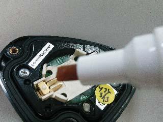
42


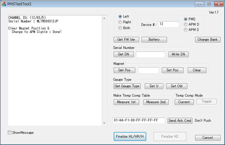
43 Magnet Calibration Cleared Magnet Calibration Completed
44 45 Troubleshooting Troubleshooting Installation Symptom Cause Solution User Dealer Installation Center
45 46 Troubleshooting Symptom Cause Solution User Dealer Installation Center Magnet Symptom Cause Solution User Dealer
46 75 Troubleshooting Sensor Connection Symptom Cause Solution User Dealer
47 Symptom Cause Calibration Solution User Dealer Troubleshooting Symptom Cause Solution User Dealer Installation Center 48
48 Symptom Cause Solution User Dealer Installation Center Troubleshooting 49
49 50 Troubleshooting Symptom Cause Solution User Dealer Installation Center Display Symptom Cause Solution User Dealer Installation Center
50 51 Troubleshooting Symptom Cause Solution User Dealer Installation Center
51 52 Troubleshooting Symptom Cause Solution User Dealer Installation Center
52 Error codes Code Description of error Data (radial) Data (tangential) Troubleshooting 53
53 Care, Maintenance, and Storage Specifications and Support 54
54 Specifications Weight : SGY-PM910H2 right side + left side About 62 g : SGY-PM910HL left side About 22 g : SGY-PM910HR right side About 40 g Dimensions : right side 58.3 mm(w) 46.1 mm(h) 21.3 mm(d) 78 mm(w) 36.7 mm(h) 7.3 mm(d) : left side 92.5 mm(w) 34.7 mm(h) 8.6 mm(d) Water resistant : This device has a water resistance rating of IPX-6/IPX-7 Communications method (sensors): ANT+ wireless Batteries : CR2032 Operation temperature: 10 C to 50 C ANT+ is a Wireless Personal Network protocol with very low power requirements using 2.4 GHz frequency band. For more information, visit Illustrations used in this manual may be different from actual appearance. Specifications and Support 55
55 PIONEER CORPORATION PIONEER ELECTRONICS (USA) INC. PIONEER ELECTRONICS OF CANADA INC. PIONEER EUROPE NV <CWW8293-B> EU
Support Manual HoistLocatel Electronic Locks
 Support Manual HoistLocatel Electronic Locks 1. S70, Create a Terminating Card for Cards Terminating Card 2. Select the card you want to block, look among Card No. Then click on the single arrow pointing
INSTALLATION INSTRUCTIONS
 INSTALLATION - REEIVER INSTALLATION INSTRUTIONS RT0 RF WIRELESS ROOM THERMOSTAT AND REEIVER MOUNTING OF WALL MOUTING PLATE - Unscrew the screws under the - Pack contains... Installation - Receiver... Mounting
 INSTALLATION INSTRUCTIONS Accessory S P/N 08E12-SZT-100 Application CR-Z Publications No. Issue Date SEP PARTS LIST Left illuminated door sill trim Right illuminated door sill trim Illumination harness
BBT057/ BBC057 BBCD057/ BBT057-NL HOLDEN COLORADO 9/2016+ HOLDEN TRAILBLAZER WD & 4WD Models
 INSTALLATION GUIDE BBT057/ BBC057 BBCD057/ BBT057-NL HOLDEN COLORADO 9/2016+ HOLDEN TRAILBLAZER 2017+ 2WD & 4WD Models Ironman 4x4 BBT/ BBC/ BBCD/BBT057-NL Bull Bars fit to a Holden Colorado 9/2016+ It
 BÄNKVÅG / BENCH SCALE Modell : SW-III / Model : SW-III ANVÄNDARMANUAL / USER MANUAL SW-III WWW.LIDEN-WEIGHING.SE 2014-03-26 OBS! Under vågen sitter en justerbar skruv (se bild). Standardinställning är
 BÄNKVÅG / BENCH SCALE ANVÄNDARMANUAL / USER MANUAL SW-III www.liden-weighing.com Svenska OBS! Under vågen sitter en justerbar skruv (se bild). Standardinställning är den för vägning. Om ni vill rengöra
81152 TRANSFER CASE SHIFT HANDLE
 Installation Instructions for TRANSFER CASE SHIFT HANDLE for 2007 2018 JEEP JK WRANGLER 1 2 3 ITEM NO. PART NO. DESCRIPTION QTY. 1 4101359 SHIFT KNOB, JEEP WRANGLER JK, MOLDED 1 2 1794720 JAM NUT, 3/8
ARC 32. Tvättställsblandare/Basin Mixer. inr.se
 ARC 32 Tvättställsblandare/Basin Mixer inr.se SE Användning och skötsel Manualen är en del av produkten. Bevara den under hela produktens livscykel. Vi rekommenderar er att noggrant läsa igenom manualen
PRESS FÄLLKONSTRUKTION FOLDING INSTRUCTIONS
 PRESS FÄLLKONSTRUKTION FOLDING INSTRUCTIONS Vänd bordet upp och ner eller ställ det på långsidan. Tryck ner vid PRESS och fäll benen samtidigt. Om benen sitter i spänn tryck benen mot kortsidan före de
Monteringsanvisning Podie T 4100 K
 Monteringsanvisning Podie T 4100 K Monteringsanvisning Förbered fundamentet 1. Montera ställfötterna. Montera tvättmaskin SV 1. Fäst gaffelbeslagen i bakkant med brickor och skruv. OBS! Placera beslagen
 Bänkvåg LCW-6S Manual/Förenklat handhavande User Manual LCW-6S www.liden-weighing.se Knappfunktioner: ON/OFF Sätter på och stänger av vågen. UNIT Skiftar vägningsenhet ZERO/TARE Nollställer vågen Tarerar
ASSEMBLY INSTRUCTIONS SCALE SQUARE - STANDARD
 ASSEMBLY INSTRUCTIONS ALL COMPONENTS Metal profile 0 mm Gripper Ceiling attachments Screws for ceiling attachements (not included) Wires Metal profile 60 mm Metal profile 00 mm Felt - Full Felt - Half
PRESS FÄLLKONSTRUKTION FOLDING INSTRUCTIONS
 PRESS FÄLLKONSTRUKTION FOLDING INSTRUCTIONS Vänd bordet upp och ner eller ställ det på långsidan. Tryck ner vid PRESS och fäll benen samtidigt. OBS! INGA STORA KRAFTER KRÄVS!! Om benen sitter i spänn tryck
BBT042/ BBC042/ BBCD042 NISSAN NAVARA D40 V STX & PATHFINDER R WD & 4WD Models
 INSTALLATION GUIDE BBT042/ BBC042/ BBCD042 NISSAN NAVARA D40 V6 2010+ STX & PATHFINDER R51 2010+ 2WD & 4WD Models Ironman 4x4 BBT/ BBC/ BBCD042 Bull Bars fit to a Nissan Navara D40 STX & Pathfinder R51.
InstalationGuide. English. MODEL:150NHighGain/30NMiniUSBAdapter
 miraclebox miraclewifi InstalationGuide English MODEL:150NHighGain/30NMiniUSBAdapter ENGLISH MIRACLE WIFI 150N & 300N USERMANUAL MIRACLEBOX.SE 1 ENGLISH Table of Contents Package Contents... 3 System Requirements
Installation Instructions
 Installation Instructions (Cat. No. 1794-IE8 Series B) This module mounts on a 1794 terminal base unit. 1. Rotate keyswitch (1) on terminal base unit (2) clockwise to position 3 as required for this type
2.45GHz CF Card Reader User Manual. Version /09/15
 2.45GHz CF Card Reader User Manual Version 2.0 2008/09/15 Install SYRD245-CF Card Reader to PDA: 1. Explorer SYRD245-CF folder of SYRIS Xtive CD-ROM 2. Check your PDA OS (Mobile5 or PPC2003) NETCF V2 currently
BBT034/ BBC034/ BBCD034 BBCD060/ BBT060-NL/ BB060-TL/ BB060-SL VOLKSWAGEN AMAROK
 INSTALLATION GUIDE BBT034/ BBC034/ BBCD034 BBCD060/ BBT060-NL/ BB060-TL/ BB060-SL VOLKSWAGEN AMAROK Ironman 4x4 BBT/ BBC/ BBCD034 BBCD060/ BBT060-NL/ BB060-TL/ BB060-SL Bull Bars fit to a Volkswagen Amarok.
Viktig information för transmittrar med option /A1 Gold-Plated Diaphragm
 Viktig information för transmittrar med option /A1 Gold-Plated Diaphragm Guldplätering kan aldrig helt stoppa genomträngningen av vätgas, men den får processen att gå långsammare. En tjock guldplätering
Plain A262. För T16 (T5) lysrör. Innehåll. Monteringsanvisning. A. Instruktion för rampmontering
 lysrör. Innehåll. Monteringsanvisning. A. Instruktion för rampmontering") Plain A262 För T16 (T5) lysrör Innehåll Ramparmatur: ändmodul En stängd gavel/ en öppen gavel Plint i båda ändarna Överkopplingssladd 1 rampgavel 1 lysrörsbytare Ramparmatur: mellanmodul Plint i en ände
Plain A262 För T16 (T5) lysrör Innehåll Ramparmatur: ändmodul En stängd gavel/ en öppen gavel Plint i båda ändarna Överkopplingssladd 1 rampgavel 1 lysrörsbytare Ramparmatur: mellanmodul Plint i en ände
Windlass Control Panel v1.0.1
 SIDE-POWER Windlass Systems 86-08950 Windlass Control Panel v1.0.1 EN Installation manual Behåll denna manual ombord! S Installations manual SLEIPNER AB Kilegatan 1 452 33 Strömstad Sverige Tel: +46 525
ASSEMBLY INSTRUCTIONS SCALE - SYSTEM
 ASSEMBLY INSTRUCTIONS 60 mm 00 mm 600 mm 000 mm R50 mm ALL COMPONENTS Metal profile 60 mm (start and end of system) Metal profile connection Wire Felt square Metal profile 00 mm Metal profile connection
Monteringsanvisning benfundament TM 8055, TM 8060, T 8118 K. Art nr ,
 Monteringsanvisning benfundament TM 8055, TM 8060, T 8118 K Art nr 102056, 102057 Monteringsanvisning Förbered fundamentet 1. Montera ställfötterna. Montera tvättmaskin SV 1. Fäst gaffelbeslagen i bakkant
ASSEMBLY INSTRUCTIONS SCALE CIRCLE - STANDARD
 ASSEMBLY INSTRUCTIONS ALL COMPONENTS Metal profile 0 mm Gripper Ceiling attachments Screws for ceiling attachements (not included) Wires Metal profile 60 mm Metal profile 00 mm Felt - Full Felt - Half
manual Facial spa Art nr: 48682 Rubicson 2016-06-08
 manual Facial spa Art nr: 8682 EN NO SV 2016-06-08 Rubicson ENGLISH Overview Use Fill the container ENGLISH 1. Make sure that the power cord is not connected to a wall socket. 1 2 2. Remove the funnel
BBT034/ BBC034/ BBCD034 VOLKSWAGEN AMAROK. Ironman 4x4 BBT/ BBC/ BBCD034 Bull Bars fit to a Volkswagen Amarok. It will take about 3 hours to install.
 INSTALLATION GUIDE BBT034/ BBC034/ BBCD034 VOLKSWAGEN AMAROK Ironman 4x4 BBT/ BBC/ BBCD034 Bull Bars fit to a Volkswagen Amarok. It will take about 3 hours to install. IMPORTANT - If your vehicle has front
Beijer Electronics AB 2000, MA00336A, 2000-12
 Demonstration driver English Svenska Beijer Electronics AB 2000, MA00336A, 2000-12 Beijer Electronics AB reserves the right to change information in this manual without prior notice. All examples in this
Digital Personvåg MANUAL H
 Digital Personvåg MANUAL H151-00-1 www. Specifikationer Kapacitet & Noggrannhet Strömförsörjning Arbetsmiljö 250kg / 0.1kg Adapter 120VAC-9VDC-50Hz / 230VAC 9VDC 50Hz Arbetstemperatur: 10 C to 35 C Förvaring,
BRUKSANVISNING for Exerfit 280 (SM370RM)
") BRUKSANVISNING for Exerfit 280 (SM370RM) BUILT FOR HEALTH INNEHÅLL SM 370RM LISTA ÖVER DELAR... 4 MONTERINGSTILLBEHÖR... 6 MONTERINGSANVISNINGAR... 7 BRUKSANVISNING... 9 SPECIFICATION... 9 VIKTIGT BETRÄFFANDE
BRUKSANVISNING for Exerfit 280 (SM370RM) BUILT FOR HEALTH INNEHÅLL SM 370RM LISTA ÖVER DELAR... 4 MONTERINGSTILLBEHÖR... 6 MONTERINGSANVISNINGAR... 7 BRUKSANVISNING... 9 SPECIFICATION... 9 VIKTIGT BETRÄFFANDE
Boiler with heatpump / Värmepumpsberedare
 Boiler with heatpump / Värmepumpsberedare QUICK START GUIDE / SNABBSTART GUIDE More information and instruction videos on our homepage www.indol.se Mer information och instruktionsvideos på vår hemsida
BRUKSANVISNING. Oscilla 910
 BRUKSANVISNING Oscilla 910 C A TEGNÉR AB BOX 20003 161 02 BROMMA TEL 08-564 822 00 FAX 08-564 822 09 INTERNET: www.categner.se E-MAIL: info@categner.se OSCILLA SM910 INNEHÅLL FRONTPANEL... 3 BAKPANEL...
INKOPPLINGSANVISNING ELTRYCKSLÅS WIRING DIAGRAM SOLENOID LOCK
 INKOPPLINGSANVISNING ELTRYCKSLÅS WIRING DIAGRAM SOLENOID LOCK SE EN S. 2-4 P. 5-7 SL 510/511 SL 520/521 SL 530-50/531-50 2013 11 07 SE TEKNISK SPECIFIKATION Driftspänning. Ström. Reed relä. Drifttemperatur.
Montageanvisning Airway system 1000/1500 Assembly instruction Airway system 1000/1500
 S.Det är lämpligt att denna information överlämnas till användaren av anläggningen. GB. It is appropriate that this information is passed on to the user of the installation. D. Diese informationen sind
LINC 23. Tvättställsblandare/Basin Mixer. inr.se 130226A
 LINC 23 Tvättställsblandare/Basin Mixer 130226A inr.se S Användande och skötsel Manualen är en del av produkten. Bevara den under hela produktens livscykel. Vi rekommenderar att noggrant läsa igenom manualen
Quick Start Guide. To switch the TV on. cable to connect the two units together. To select the TV broadcasts. To HDMI connection on.
 Quick Start Guide 1 Insert the batteries into the remote control Lift the cover on the back of the remote upward gently. Install two AAA batteries. Make sure to match the + and - ends of the batteries
IRAB Mottagare sida 2-5 Tele Radio AB Mottagare sida 6
 IRAB Mottagare sida -5 Tele Radio AB Mottagare sida 6 Installation of receiver type smd 700 4 RELAY FUNCTIONS / -4 VAC/DC PCB TYPE NO: LWEG 4L Rev: 95-09 Installation: Install the receivers in a protected
Instruction Manual. Svenska, English. Power Bank. Model: PRBN
 Instruction Manual Svenska, English Power Bank Model: PRBN Innehåll / Content Innehåll Säkerhetsföreskrifter... 4 Delar... 5 Specifikationer... 6 Miljö / Lag och säkerhet / Förbehåll... 7 Content Safety
ASSEMBLY INSTRUCTIONS
 ASSEMBLY INSTRUCTIONS Unite XL2 EXTEND COMPONENTS End tabletop 190/260 cm Middle tabletop 140/210 cm 1 Assemble all the legs, start by putting a foot into an inner leg. Slide the outer leg over the inner
nwind and nwind-race transducer Twin Fin Installation Manual English Installationsmanual Svensk
 nwind and nwind-race transducer Twin Fin Installation Manual English Installationsmanual Svensk English 12-1 English This manual is written for nwind transducer 1.00 Edition: Jan 2011 12-2 English nwind
Monteringsanvisning benfundament TM 9060, TM 9070, T 9153 E/K/VP. Art nr , ,
 Monteringsanvisning benfundament TM 9060, TM 9070, T 9153 E/K/VP Art nr 102058, 102059, 102030 Monteringsanvisning SV Förbered fundamentet 1. Montera ställfötterna. 4. Fundamentet skall alltid tippsäkras.
Bathtub Filler CN EN. TBP02201 Type / TBP02202 Type. Installation Manual. Continued on the back cover
 03N74E Installation Manual 207.8 Bathtub Filler TBP0220 Type / TBP02202 Type For best results, install the product correctly according to the instructions in this Installation Manual. After installation,
IR-tork Modell FY-2WH 2000W. Artikelnummer
 IR-tork Modell FY-2WH 2000W Artikelnummer 491528 Om Verktygsboden: Vi har arbetat med verktyg och maskiner sedan mitten av åttiotalet. Vår marknad är Sverige och Borås är vår bas. Här fi nns 3 000 kvm
Quick Start. English Svenska PRIMACY. Printing settings and winsign
 Quick Start English Svenska PRIMACY Printing settings and winsign 2016-05-26 Before Printing Quick Start Primacy Install the printer according to the supplier s instructions, please see the PRIMACY user
LÄNKHJUL S3. Monteringsanvisning för: Länkhjul S3
 MONTERINGSANVISNING LÄNKHJUL S3 Art.no. 8822117 Rev.2018-01 Link to english Monteringsanvisning för: Länkhjul S3 art.nr. 2002010 Länkhjul S3 90 mm art.nr. 2002020 Länkhjul S3 120 mm art.nr. 2002030 Länkhjul
Manual/Förenklad handhavande User Manual. LPW-Serien.
 Manual/Förenklad handhavande User Manual LPW-Serien www.liden-weighing.se Svenska INNEHÅLL 1. INLEDNING... 2 2. BESKRIVNING... 2 Tangentbord... 3 Display.....4 3. Användning.....4 3.1 Grundläggande Användning..4
SAFETY PRECAUTIONS SPECIFICATIONS
 SAFETY PRECAUTIONS Read the instructions carefully before use and save them for future reference. Before you connect the appliance: Ensure that the voltage rating on the type plate corresponds to your
P650 - Takscreen. Installationsguide EN
 P650 - Takscreen Installationsguide 1309-150507EN V650-Tallinn Installation manual Montera främre linhjul 12 13 Placera linan över linhjulet och skruva tillbaka täcklocket på linhjulhuset (7). Öppna linhjulshuset
Får endast utföras av behörig personal. May only be carried out by authorized electrician
 Instruktion för DMIS Instruction for DMIS FLE400FC, FLE850MP, W3400H, W4400H/W4600H (-980/1287) W3850H/W31100H, W4850/W41100H (-1220/636) Clarus Control 471 1530-75 2016.05.04 Får endast utföras av behörig
Styrteknik: Binära tal, talsystem och koder D3:1
 Styrteknik: Binära tal, talsystem och koder D3:1 Digitala kursmoment D1 Boolesk algebra D2 Grundläggande logiska funktioner D3 Binära tal, talsystem och koder Styrteknik :Binära tal, talsystem och koder
Installation. Twice Nisch. Twice Corner SVENSKA ENGLISH
 Installation Arrow Skandinavien AB Tel: +46 (0)31 330 00 10 www.arrowshower.com Twice Corner Twice Nisch SVENSKA (SV) Installationsanvisning för Arrow duschvägg. Vi förbättrar ständigt våra installationsanvisningar.
IR-tork Modell FY-6DH 6000W. Artikelnummer
 IR-tork Modell FY-6DH 6000W Artikelnummer 491527 Om Verktygsboden: Vi har arbetat med verktyg och maskiner sedan mitten av åttiotalet. Vår marknad är Sverige och Borås är vår bas. Här fi nns 3 000 kvm
IMPORTANT! RETAIN FOR FUTURE REFERENCE PLEASE READ CAREFULLY VIKTIGT! BEHÅLL FÖR FRAMTIDA REFERENS LÄS IGENOM INSTRUKTIONSMANUALEN
 Heart & Stripes Junior Bed Instructions Manual Instruktions Manual IMPORTANT! RETAIN FOR FUTURE REFERENCE PLEASE READ CAREFULLY VIKTIGT! BEHÅLL FÖR FRAMTIDA REFERENS LÄS IGENOM INSTRUKTIONSMANUALEN Thank
SAFETY PRECAUTIONS SPECIFICATIONS
 SAFETY PRECAUTIONS Read the instructions carefully before use and save them for future reference. Before you connect the appliance: Ensure that the voltage rating on the type plate corresponds to your
Contents / Innehållsförteckning
 Contents / Innehållsförteckning Copyright This manual is the copyright of CI no 55650-4137. No part of this manual may be revised, copied or transmitted in any way without written permission from CI no
2.1 Installation of driver using Internet Installation of driver from disk... 3
 &RQWHQW,QQHKnOO 0DQXDOÃ(QJOLVKÃ'HPRGULYHU )RUHZRUG Ã,QWURGXFWLRQ Ã,QVWDOOÃDQGÃXSGDWHÃGULYHU 2.1 Installation of driver using Internet... 3 2.2 Installation of driver from disk... 3 Ã&RQQHFWLQJÃWKHÃWHUPLQDOÃWRÃWKHÃ3/&ÃV\VWHP
Product configurations Produire configuration Produkt konfigurationen Producto configuraciones Produkt konfigurationerna
 Product configurations Produire configuration Produkt konfigurationen Producto configuraciones Produkt konfigurationerna 1 2 3 Ref. 3800 2360, Ver 2005-09 2 1. Keypad K900; includes TOM-Net terminators.
Diskant Yta eller Vikelfäste montering Mount
 Installation och Bruksanvisning Inledning Välj fästpunkterna för dina dome TW250 Silk diskanter. Kom ihåg att för bästa prestanda bör diskanterna monteras så nära mitten av bas som möjligt, med fri, direkt
Quick Start. English Svenska. Moca
 Quick Start English Svenska Moca 2015-08-20 Before Printing Install the printer according to the supplier s instructions, please see the Moca user guide (chapter 3-1) at the installation CD. Choose Moca
BBT014/ BBC014/ BBCD014 PJ & PK FORD RANGER WD & 4WD Models
 INSTALLATION GUIDE BBT014/ BBC014/ BBCD014 PJ & PK FORD RANGER 2007+ 2WD & 4WD Models Ironman 4x4 BBT/ BBC/ BBCD014 Bull Bars fit to a Ford Ranger. It will take about 3 hours to install. NOTE: This product
Monteringsanvisning Nödutrymningsbeslag ASSA 179E
 Monteringsanvisning Nödutrymningsbeslag ASSA 179E Denna monteringsanvisning avser nödutrymningsbeslag ASSA 179E med artikelnummer 364371 i kombination med låshus Abloy EL580 med artikelnummer EL580100011.
Nathi Skötbord Changing unit Table à langer murale Wickeltisch Verschoontafel Puslebord Cambiador de pared Přebalovací pult Fasciatoio
 Nathi Skötbord Changing unit Table à langer murale Wickeltisch Verschoontafel Puslebord Cambiador de pared Přebalovací pult Fasciatoio Пеленальный стол Tested and approved according to SS-EN 12221:2008+A1_2013
Multifunktions-Detector Multi detector
 Multifunktions-Detector Multi detector... 7 Numeric Display Low Battery Alert Wood Alternating Current Metal Sensor Range Metal Metal Object Sensor Range Alternating Current Battery Compartment Bar Graph-Display
BATH MIXER 160 LINC 21. incl. HAND SHOWER. inr.se
 LINC 21 BATH MIXER 150 BATH MIXER 160 incl. HAND SHOWER 110309 inr.se Innan montering Vi förordar en sakkunnig VVS-installatör vid installation och service. Ledningarna ska renspolas innan installation.
STANDARD. UTM Ingegerd Annergren UTMS Lina Orbéus. UTMD Anders Johansson UTMS Jan Sandberg
 1(7) Distribution: Scania, Supplier Presskruvar med rundat huvud - Metrisk gänga med grov delning Innehåll Sida Orientering... 1 Ändringar från föregående utgåva... 1 1 Material och hållfasthet... 1 2
Installation Instructions
 Installation Instructions (Cat. No. 1771-P4R and 1771-P6R) This document provides you with the following information: When you receive your 1771-P4R or -P6R power supply, you should see the following in
LK ICS.2 Quick Guides - Installation & Reset
 LK ICS.2 Quick Guides - Installation & Reset Installation English Installation Svenska Reset English Reset Svenska Back to start Installation of ICS.2 Systems V Connecting actuators and wired thermostats
VARIOBARRIER S/M MIMSAFE BY CHOICE
 VAROBARRR S/M MMSA BY CHOC K L A B D M C H A B C D 522 K 524 Right leg Right leg 514L 514R 510L 510R L 526L M 526R S508 S509 521 6X 521 + H 527 529 528 8X/1 18X 8X/1 M-460641AL M-SM6X14A M-460641B M-M37202_2014
Droppställning / IV stand
 MONTERINGSANVISNING / ASSEMBLY INSTRUCTIONS Droppställning / IV stand Fellow Classic Art. nr. / Art. no: 08814 1 SVENSKA Produktbeskrivning Droppställningen består av följande delar: - Klamma, 3 st - Bottenstöd
2. lyft bilen med domkraft vänster fram så att hjulet går fritt från golvet.
 Classic Power Nition för Citroen DS/ID/TA. Elektronisk fördelare med i en signalprocessor förprogrammerade tändkurvor för alla förekommande motorer i Traction Avant, HY & ID/DS. Lämplig för 6 och 12 volt:
Reservdelskatalog Parts Catalogue COMBI 40 AE /S15 - Season 2017
 2306/S1 - Season 201 Use GLOBAL GARDEN PRODUCT Genuine Spare Parts specified in the parts list for repair and/or replacement. The contents described in the parts list may change due to improvement. The
Rev No. Magnetic gripper 3
 Magnetic gripper 1 Magnetic gripper 2 Magnetic gripper 3 Magnetic gripper 4 Pneumatic switchable permanent magnet. A customized gripper designed to handle large objects in/out of press break/laser cutting
Monteringsanvisning / Installation instruction Felsökningsschema Styxx Troubleshooting Styxx STEG 1
 Mora Armatur Box 480 SE-792 27 MORA SWEDEN www.moraarmatur.com Monteringsanvisning / Installation instruction Troubleshooting Styxx Rev. 001-14.11. MA nr 1005138 STEG 1 Kontrollera så att medföljande tillhörande
Svenska()(Bruksanvisning(för(handdukstork()(1400(x(250(mm(
(Bruksanvisning(för(handdukstork()(1400(x(250(mm(") 1 Svenska()(Bruksanvisning(för(handdukstork()(1400(x(250(mm( Läsnogaigenombruksanvisningeninnanproduktenanvänds 6Kontrolleraattduharalladelarenligtpacklistannedan.Kontaktadinåterförsäljareomnågondelär
1 Svenska()(Bruksanvisning(för(handdukstork()(1400(x(250(mm( Läsnogaigenombruksanvisningeninnanproduktenanvänds 6Kontrolleraattduharalladelarenligtpacklistannedan.Kontaktadinåterförsäljareomnågondelär
Verktyg som behövs. LX HD Sit-Stand Desk Mount LCD Arm SVENSKA. 20" (508 mm) 14-30 lbs (6.35-13.61 kg)
 14-30 lbs (6.35-13.61 kg)") ASSEMBLY INSTRUCTIONS LX HD Sit-Stand Desk Mount LCD Arm 14-30 lbs (6.35-13.61 kg) Maximal skärmstorlek * = 46 * Begränsat till max 30 lbs (13,61 kg) 0.78"-2.56" (20-65mm) 0.78-2.25 (20-57mm) 0.5"-2.5"
ASSEMBLY INSTRUCTIONS LX HD Sit-Stand Desk Mount LCD Arm 14-30 lbs (6.35-13.61 kg) Maximal skärmstorlek * = 46 * Begränsat till max 30 lbs (13,61 kg) 0.78"-2.56" (20-65mm) 0.78-2.25 (20-57mm) 0.5"-2.5"
Active Speaker System X-Line 50 AW
 Active Speaker System X-Line 50 AW Important Safety Information: Read all documentation before operating your equipment. Retain all documentation for future reference. Save the carton and packing material
ELPATRON MED TERMOSTAT
 ELPATRON MED TERMOSTAT 090821 inr.se SVENSKA Viktig information! 3 Anslutningsmöjligheter 4 Översikt funktioner 5 Montering termostat 6 Användarguide termostat Tork 8 Timer 8 IR-anslutning 8 Antifrys 9
SCdefault. 9-5 Installation instructions
 SCdefault 9-5 Installation instructions SITdefault Tuning Kit MONTERINGSANVISNING INSTALLATION INSTRUCTIONS MONTAGEANLEITUNG INSTRUCTIONS DE MONTAGE Accessories Part No. Group Date Instruction Part No.
Calculate check digits according to the modulus-11 method
 2016-12-01 Beräkning av kontrollsiffra 11-modulen Calculate check digits according to the modulus-11 method Postadress: 105 19 Stockholm Besöksadress: Palmfeltsvägen 5 www.bankgirot.se Bankgironr: 160-9908
CANALKLER 250S. Gänga i tum Thread in inch
 Skruvkoppling/Reusable coupling CANALKLER kopplingar används under högt tryck. Använd endast kopplingar som rekommenderas av Trelleborg och följ monteringsanvisningarna noggrant. Kontrollera så att slangen
Montageanvisning Airway system 1000/1500 Assembly instruction Airway system 1000/1500
 S.Det är lämpligt att denna information överlämnas till användaren av anläggningen. GB. It is appropriate that this information is passed on to the user of the installation. D. Diese informationen sind
Discovery FSQ, IAA Utgåva/Edition 11. SE Habo. Klass 2 IAA FSQ-I 26W. 4 mm c c mm N L
 Discovery FQ, IAA E - 566 80 Habo 3 4 4 mm c c mm 5 IAA Klass FQ-I 6W För armatur klass II,eller armatur för IAA/FQ-I 6W skall medföljande skyddsslang användas. For luminaire of Class II,or luminaire for
1. Unpack content of zip-file to temporary folder and double click Setup
 Instruktioner Dokumentnummer/Document Number Titel/Title Sida/Page 13626-1 BM800 Data Interface - Installation Instructions 1/8 Utfärdare/Originator Godkänd av/approved by Gäller från/effective date Mats
LINC MODELL 13. INR SVERIGE AB Kosterögatan 15 SE-211 24 Malmö 13 EN 1428:2005+A1:2008
 LINC MODELL 13 151005 Produkten är anpassad till branschregler Säker Vatteninstallation. INR garanterar produktens funktion om branschreglerna och monteringsanvisningen följs. INR SVERIGE AB Kosterögatan
Installationsguide. EG200 Multi WAN Residential Gateway. v
 Installationsguide v. 2018-11-29 1 STATUS 3 5 2 4 WAN INTERNET Ovansida WIFI ETHERNET Baksida 7 TELE 6 8 WPS EXT Den här installationsguiden hjälper dig att installera Inteno. kopplas in i ditt Ethernet-baserade
electiaprotect GSM SEQURITY SYSTEM Vesta EZ Home Application SMART SECURITY SYSTEMS! SVENSKA ios... 2-4 Android... 5-7
 GSM SEQURITY SYSTEM Vesta EZ Home Application SVENSKA ios... 2-4 Android... 5-7 ENGLISH ios... 8-10 Android... 11-13 electiaprotect SMART SECURITY SYSTEMS! 1.1. Vesta EZ Home för ios Vesta EZ Home för
FLUID SOLUTIONS 700ZDT & 700NDT. NAMUR Solenoid Valve 3/2 5/2 INSTALLATION, OPERATION & MAINTENANCE MANUAL. JWB USA, Inc. TUNING FLUID SOLUTIONS
 700ZDT & 700NDT NAMUR Solenoid Valve 3/2 5/2 INSTALLATION, OPERATION & MAINTENANCE MANUAL TUNING JWB USA, Inc. Table of content TABLE OF CONTENTS CHAPTER 1: PRODUCT DESCRIPTION 1 CHAPTER 2: METHOD of OPERATION
Anvisning för Guide for
 Anvisning för Guide for PRISMA SENSOR 1 96243235zPC Montering i tak/installation in the ceiling Byte av kupa/change of diffuser 2 Installation Installation från gavel / Installation from the end Installationskabel
TEXTURED EASY LOCK BLOCK INSTALLATION GUIDE. australianpaving.com.au
 TEXTURED EASY LOCK BLOCK INSTALLATION GUIDE 1800 191 131 australianpaving.com.au TEXTURED EASY LOCK BLOCK The Textured Easy Lock Block retaining wall system is the premium retaining wall product for near
Molift Raiser 75135G Etac Box 203, Anderstorp Sweden Tel Fax
 7G 8-0-07 SE SE EN EN Till och med serienummer 0900 Från serienummer 0900 Up to serial number 0900 From serial number 0900.... Etac Box 0, Anderstorp Sweden Tel + 7 8 7 00 Fax + 7 8 7 90 www.etac.com Svenska
Quick Start Guide Snabbguide
 Quick Start Guide Snabbguide C Dictionary Quick Start Thank you for choosing C Dictionary and C-Pen as your translation solution. C Dictionary with its C-Pen connection will make translation easy and enable
INSTRUKTION DATOR MASTER B430
 Master B430 2011/1/5P1/5 INSTRUKTION DATOR MASTER B430 KNAPPFUNKTIONER: MODE För att bekräfta alla inmatade träningsuppgifter och för att påbörja ett program. RESET Vid tryck på denna knapp återgår man
Installation Instructions
 Installation Instructions TrailVie w So ft To p For proper installation and best possible fit, please read all instructions BEFORE you begin. For technical assistance or to obtain missing parts, please
This manual should be saved! EcoFlush Manual. Wostman 2018:2
 This manual should be saved! EcoFlush Manual Wostman 2018:2 ENGLISH Important! This manual should be saved by the owner! It s important to read the whole manual before installation. EcoFlush gives the
LX Desk Mount LCD Arm
 ASSEMBLY INSTRUCTIONS LX Desk Mount LCD Arm * Den vertikala hissens lägsta rörelseomfång minskas upp till 3 tum (76 mm) när armen justeras för att kunna stödja över 20 lbs (9 kg). 8.5 (216 mm) 5-25 lbs*
Lösenordsportalen Hosted by UNIT4 For instructions in English, see further down in this document
 Lösenordsportalen Hosted by UNIT4 For instructions in English, see further down in this document Användarhandledning inloggning Logga in Gå till denna webbsida för att logga in: http://csportal.u4a.se/
LINC Modell 17 130624A
 LINC Modell 17 130624A Denna produkt är anpassad till Branschregler Säker Vatteninstallation. INR garanterar produktens funktion om branschregler och monteringsanvisning följs. INR SVERIGE AB Kosterögatan
Metodprov för kontroll av svetsmutterförband Kontrollbestämmelse Method test for inspection of joints of weld nut Inspection specification
 Stämpel/Etikett Security stamp/lable Metodprov för kontroll av svetsmutterförband Kontrollbestämmelse Method test for inspection of joints of weld nut Inspection specification Granskad av Reviewed by Göran
900 Installation instructions. SITdefault F930A205
 3456789 900 Installation instructions SITdefault F930A05 3456748946 83 54 5 4 6 0 7 8 3 9 3 F930A390 Amplifier Treble speaker (x4) 3 Bass speaker (x) 4 Screw (x8) 5 Cover, connector housing 6 Optical cable
SVENSK STANDARD SS-EN ISO 19108:2005/AC:2015
 SVENSK STANDARD SS-EN ISO 19108:2005/AC:2015 Fastställd/Approved: 2015-07-23 Publicerad/Published: 2016-05-24 Utgåva/Edition: 1 Språk/Language: engelska/english ICS: 35.240.70 Geografisk information Modell
Ringmaster RM3 - RM 5 RM3 RM 4 RM 5
 RM3 - RM 5 Ringmaster We offer ball pickers in 5 different sizes with a picking width of up to 6 m. RM3 - RM5 has a self-supporting chassis so that the collected balls do not place a load on the picking