GV-SNVR System SNVR V21 -UM-A
|
|
|
- Margareta Forsberg
- för 6 år sedan
- Visningar:
Transkript


1 GV-SNVR System User s Manual SNVR V21 -UM-A
2 2016 GeoVision, Inc. All rights reserved. Under the copyright laws, this manual may not be copied, in whole or in part, without the written consent of GeoVision. Every effort has been made to ensure that the information in this manual is accurate. GeoVision, Inc. makes no expressed or implied warranty of any kind and assumes no responsibility for errors or omissions. No liability is assumed for incidental or consequential damages arising from the use of the information or products contained herein. Features and specifications are subject to change without notice. Note: No memory card slot or local storage function for Argentina. GeoVision, Inc. 9F, No. 246, Sec. 1, Neihu Rd., Neihu District, Taipei, Taiwan Tel: Fax: Trademarks used in this manual: GeoVision, the GeoVision logo and GV series products are trademarks of GeoVision, Inc. Windows is the registered trademarks of Microsoft Corporation. December 2016 i
3 Preface Welcome to the GV-SNVR System User s Manual. The GV-SNVR System has a series of models designed to meet different needs. This manual is designed for the following models and firmware versions: Models Firmware Version GV-SNVR0411 V2.10 GV-SNVR0400F V1.11 GV-SNVR1600 V1.21 ii
4 Caution The GV-SNVR System is designed only for indoor usage. iii
5 Contents Chapter 1 Introduction Features Models Packing List and Package GV-SNVR Single Package GV-SNVR Bundled Package... 5 GV-SNVR0400F Compatible Products and System Requirements Supported GV-IP Cameras Supported GeoVision Applications System Requirements Options Overview Front View Rear View Chapter 2 Getting Started Installation GV-SNVR GV-SNVR0400F GV-SNVR Connecting the GV-SNVR Network Connection for GV-SNVR Setting Up GV-IP Camera Automatically Setting Up GV-IP Camera Manually Connecting GV-IP Cameras Manually Connecting Third-Party IP Camera Changing Camera IP Address and Assigning Channels Formatting the Hard Drive Main Screen Enabling Recording Playing Back Video Live Monitoring Snapshot Audio PTZ Control iv
6 Chapter 3 System Configuration Camera Recording Network Storage Display Service Connecting GV-SNVR with GV-Center V2 and GV-Vital Sign Monitor Connecting GV-Eye to GV-SNVR System Chapter 4 Video Playback Timeline Player ecording Backup Chapter 5 Remote Access to the GV-SNVR Accessing through Web browser Live View Screen Snapshot of Live Video Picture-in-Picture View Picture-and-Picture View Digital PTZ Control Fisheye View Accessing through Mobile Device Accessing through GV-Edge Recording Manager Accessing through GV-Control Center Chapter 6 Advanced Applications Upgrading System Firmware Using the GV-IP Device Utility Looking up the IP Address Accessing the Live View Upgrading System Firmware Backing up and Restoring Settings Appendix 80 v


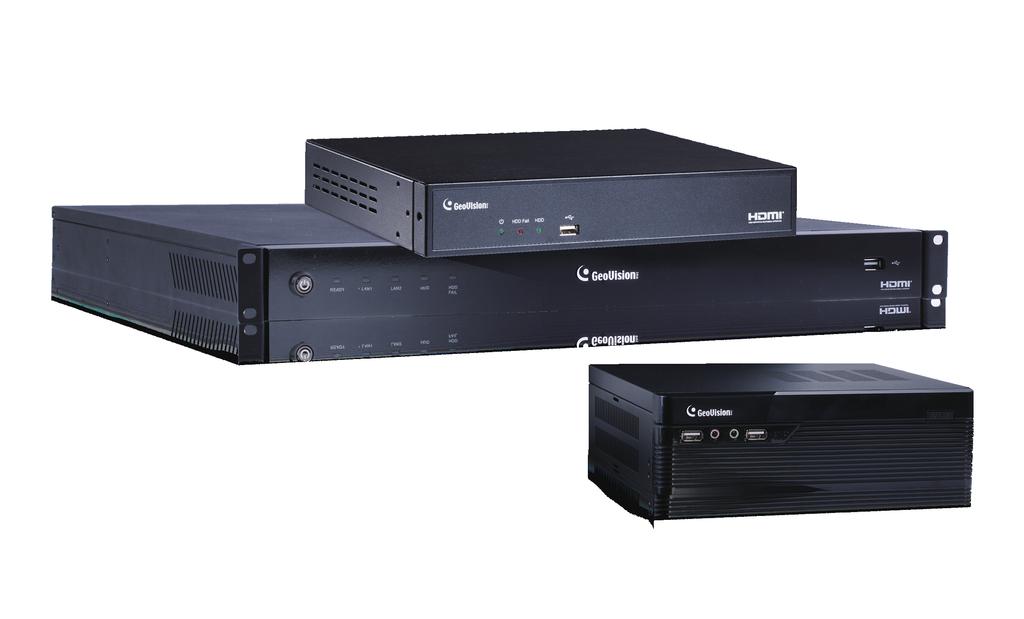
7 1 Introduction Chapter 1 Introduction GV-SNVR is an H.264/H.265 linux-embedded Standalone Network Video Recorder which records video files directly to the internal hard drive, supporting up to 4 / 16 channels of GV-IP Cameras for network surveillance. With the feature of a Full HD HDMI video output, the GV-SNVR eliminates the need for a separate PC to view and play back video from the unit. Its USB ports allow you to connect a USB flash drive to import or export system settings, update firmware, save snapshot files and back up video in AVI format. Optionally, you can connect a GV-Joystick V2 to control PTZ cameras. Moreover, you can remotely access the live view through mobile devices or Web browsers with advanced video features. Access Live View Up to 10 / 34 Connections Up to 4 / 16 GV-IP Cameras Play back Recording GV-SNVR + Access Live View GV-Edge Recording Manager GV-Control Center GV-Vital Sign Monitor GV-Center V2 GV-Joystick V2 (for PTZ Camera) Web Browser Figure 1-1 Note: H.265 video compression is only supported by GV-SNVR
8 1.1 Features 4-Channel video recording (for GV-SNVR0411 / 0400F ) 16-Channel video recording (for GV-SNVR1600) Automatic search and set-up for GV-IP Cameras Support for third-party IP cameras through ONVIF and RTSP (for GV-SNVR0411) 4-Port PoE (IEEE 802.3af) for camera connection (for GV-SNVR0411) Video Resolution Model Resolution GV-SNVR0411 Up to 3840 x 2160 per channel * GV-SNVR0400F Up to 1920 x 1080 per channel * GV-SNVR1600 Up to 2592 x 1944 for the first channel * Up to 1920 x 1080 per channel * Dual streams support Continuous, motion and scheduled recordings Timeline playback Multi-channel playback Display of HDD status and system temperature DST (Daylight Saving Time) support NTP (Network Time Protocol) support GeoVision DDNS server support notification for recording error and password retrieval Recording export Remote live view through Web browser PTZ control using GV-Joystick V2 or on-screen panel HDD Storage Model GV-SNVR0411 GV-SNVR0400F GV-SNVR1600 Storage 1 SATA HDD drawer (3.5 ) for up to 8 TB storage 1 SATA HDD drawer (3.5 ) for up to 4 TB storage 4 SATA HDD drawer (3.5 ) for up to 16 TB storage Smart device access (ios and Android) Support for 13 languages *The resolutions of stream 1 and 2 both must meet the requirements noted in Appendix C. 2


 4.")
9 1 Introduction 1.2 Models The GV-SNVR has the following models: GV-SNVR0411 GV-SNVR0400F GV-SNVR Supports 1 SATA HDD (3.5 ) - Records up to 4 IP channels - Supports 4 SATA HDD (3.5 ) - Records up to 16 IP channels 1.3 Packing List and Package You can choose to purchase a GV-SNVR0411 / 0400F / 1600 package or a GV-SNVR0400F bundled package which includes 4 GV-Target IP Camera of your choice, and with or without a GV-PoE switch GV-SNVR Single Package GV-SNVR GV-SNVR AC Power Cord 3. AC/DC Adapter (DC 52V, 1.38 A, 72 W) 4. SATA Cable 5. HDD Power Cable 6. Screw x 4 (for HDD) 7. Rubber Foot x 4 (for HDD) 8. USB Mouse 9. Firmware CD/DVD 10. Software CD/DVD 11. Warranty Card 3

 6. Rubber Foot x 4 7. USB Mouse 8. Firmware CD/DVD 9.")
10 GV-SNVR0400F 1. GV-SNVR0400F 2. AC Power Cord 3. AC/DC Adapter (DC 19V, 3.42A, 65 W) 4. Screw x 6 (for HDD) 5. SATA Cable 6. Firmware CD/DVD 7. Software CD/DVD 8. Quick Start Guide 9. Warranty Card GV-SNVR GV-SNVR AC Power Cord 3. SATA Cable x 4 4. HDD Mounting Bracket Kit (4 pairs and 32 screws included) 5. Rack Mount Kit (2 L-shaped brackets and 6 screws included) 6. Rubber Foot x 4 7. USB Mouse 8. Firmware CD/DVD 9. Software CD/DVD 10. Quick Start Guide 11. Warranty Card 4

11 1 Introduction GV-SNVR Bundled Package GV-SNVR0400F 1. GV-SNVR0400F Package x 1 2. Target IP Camera x 4 3. GV-POE0400 x 1 Note: For the Target IP Camera, select any 4 models from GV-EBL1100 / 2100, GV-EBX1100 / 2100, GV-EDR1100 / 2100, GV-EFD1100 / For more information, contact our sales representatives. 5
12 1.4 Compatible Products and System Requirements Supported GV-IP Cameras EXCEPT GV-SNVR System Firmware Not Supported Models * SNVR0400F V1.11 SNVR0411 V2.10 SNVR1600 V1.21
13 1 Introduction IMPORTANT: channel 1 channel Supported GeoVision Applications For GV-SNVR0411 Note For GV-SNVR0400F / 1600
14 1.4.3 System Requirements Recommended Hard Disks GV-SNVR0411 supports 1 SATA HDD (3.5 ) with up to 8 TB capacities, GV-SNVR0400F supports 1 SATA HDD (3.5 ) with up to 4 TB capacities, and GV-SNVR1600 supports 4 SATA HDD (3.5 ) with total up to 16 TB capacities. For system efficiency, it is recommended to use the enterprise-level hard disk drives instead of desktop-level or green HDD. For tested hard disk drives, see Appendix. Note: The GV-SNVR does not support the 2.5 SATA HDD. Supported Web Browsers Internet Explorer 8 or later Google Chrome Mozilla Firefox Safari (Only supported by GV-SNVR0411) Microsoft Edge (Only supported by GV-SNVR0411) 8
15 1 Introduction 1.5 Options Optional devices can expand your GV-SNVR s capabilities and versatility. Contact your dealer for more information. GV-Joystick V2 GV-POE Switch Slide Rail Kit The GV-Joystick V2 facilitates the PTZ camera control. It can be plugged into the GV-SNVR for independent use to empower the operation of PTZ cameras. The GV-POE Switch is designed to provide power along with network connection for IP devices. The GV-POE Switch is available in various models with different numbers and types of ports. The Slide Rail Kit is used to mount a rail for the GV-SNVR1600 in a 19 cabinet. 9

16 1.6 Overview Front View GV-SNVR Figure 1-1 No. Name Function 1 Power LED Shows constant Green when the power is supplied for the device. 2 HDD Fail LED Shows constant red when the following situations occur: No hard drive is installed. The hard drive is not formatted. The hard drive fails. 3 HDD LED Blinks Green when the HDD is writing or reading data. 4 USB 2.0 Port Connects to a keyboard, mouse, USB flash drive or GV-Joystick V2. 10

17 1 Introduction GV-SNVR0400F Figure 1-2 No. Name Function 1 USB 2.0 Port Connects to a keyboard, mouse, USB flash drive or GV-Joystick V2. 2 Audio In Not functional. 3 Audio Out Connects to a speaker. 4 Power LED Shows constant blue when the power is supplied for the device. 5 HDD Error LED Shows constant red when the following situations occur: No hard drive is installed. The hard drive is not formatted. The hard drive fails. 6 Power Button Turns on/off the power. 11

18 GV-SNVR Figure 1-3 No. Name Function 1 Power Button Turns on/off the power. 2 Power LED Shows constant blue when the power is supplied for the device. 3 HDD Status LED Flashes blue when the hard drive is writing or reading data. 4 HDD Error LED Shows constant red when the following situations occur: No hard drive is installed. The hard drive is not formatted. The hard drive fails. 5 WAN LED Flashes blue when the WAN port is receiving activity. 6 LAN LED Flashes blue when the LAN port is receiving activity. 7 USB 2.0 Port Connects to a keyboard, mouse, USB flash drive or GV-Joystick V2. 12

19 1 Introduction Rear View GV-SNVR Figure 1-4 No. Name Function 1 DC 52 V (Power Input) Connects to power supply. 2 Megabit PoE Ports 3 WAN Connects to the network. 4 USB 2.0 Port 5 Default Button 6 HDMI Output Connects to a HD TV. Connects to cameras, delivering power and network connection to the cameras. Connects to a keyboard, mouse, USB flash drive or GV-Joystick V2. Restores the device to default settings. Press the button for 15 seconds to load default. 13

20 GV-SNVR0400F Figure No. Name Function 1 Gigabit Ethernet Port Connects to the network. 2 HDMI Output Connects to a HD TV. 3 USB 2.0 Port 4 Default Button 5 Power Input Connects to power supply. Connects to a keyboard, mouse, USB flash drive or GV-Joystick V2. Restores the device to default settings. Press the button for 15 seconds to load default. 14
21 1 Introduction GV-SNVR Figure 1-6 No. Name Function 1 Audio Microphone In Port Not functional. 2 VGA Monitor Output Connects to a VGA monitor. 3 HDMI Port Connects to a HD TV. 4 USB 2.0 Port x 4 Connects to a keyboard, mouse, USB flash drive or GV-Joystick V2. 5 Power Input Connects to power supply. 6 Gigabit Ethernet Port (LAN) Connects to the network. 7 Gigabit Ethernet Port (WAN) Connects to the network. 8 Audio Line Out Port Connects to a headphone. 9 Audio Line Out Port Connects to a speaker. Note: When the two Ethernet ports (No. 6 and No. 7) are used together, one is LAN port and the other is WAN port. 15


22 Chapter 2 Getting Started 2.1 Installation The GV-SNVR uses SATA hard drive for video data storage. Before recording, be sure to install the hard drive GV-SNVR0411 Installing the Hard Drive Follow the steps below to install the hard drive to GV-SNVR Unscrew three screws on the bottom and two screws on the sides; then remove the cover. Figure Place the supplied rubber foots on four of the six oval holes and place the hard drive in the drive drawer as below by aligning the four holes. Figure 2-2 Figure
.")
23 2 Getting Started 3. Secure the hard drive from the back of the drawer using the supplied 4 screws. Figure Connect the SATA Power Cable and Data Cable to the hard drive. Data Cable SATA Power Cable Figure Assemble the cover with the device by tightening the screws on the bottom and sides. panel (Figure 2-1). The hard drive is now ready to use. 17


24 2.1.2 GV-SNVR0400F Installing the Hard Drive Follow the steps below to install the hard drive to GV-SNVR0400F. 1. Unscrew the two screws on the rear panel and remove the cover. Figure Unscrew the drive drawer and take it out from the device. Figure


25 2 Getting Started 3. Place the hard drive in the drive drawer as below by aligning the three holes. Figure Secure the hard drive with the drive drawer using the supplied 6 screws (3 screws on each side). Figure Connect the SATA Power Cable and Data Cable to the hard drive. SATA Power Cable Data Cable Figure
.")


26 6. Put the drive drawer back in the device and secure the two screws on the drive drawer (Figure 2-7). 7. Assemble the cover with the device by tightening the screws on rear panel (Figure 2-6). The hard drive is now ready to use GV-SNVR1600 Installing the Hard Drive Follow the steps below to install the hard drive to the GV-SNVR Loosen the 6 screws and remove the cover. Figure Assemble the mounting brackets with the hard drive and tighten the screws on both sides. R - Right L - Left Figure 2-12 Note: Each mounting bracket is labeled L or R for recognition. Align the mounting bracket with the holes on the hard drive and make sure it is secured to the correct side. 20


27 2 Getting Started 3. Align the mounting bracket with the holes inside the unit. Front Panel Left Right Rear Panel Figure Tighten the 4 screws on the side of the hard drive. Front Panel Rear Panel Side View of the HDD Figure Connect the SATA Power Cable and Data Cable to the hard drive. SATA Power Cable Data Cable Figure


28 6. To install more HDDs, repeat the steps above. 7. Place the cover back and tighten the screws. The hard drive is now ready for use. Installing the L-Shaped Brackets Tighten the 6 screws to secure and attach the 2 L-shaped brackets to each side of GV-SNVR1600. Figure

29 2 Getting Started 2.2 Connecting the GV-SNVR Follow the steps below to connect the GV-SNVR. 5 1 GV-SNVR GV-SNVR0400F 23

30 GV-SNVR1600 Figure Connect the GV-SNVR to power. 2. Connect the GV-SNVR to the LAN port using the Ethernet cable. 3. Connect a speaker to the Audio Line Out port. 4. Connect a HDTV to HDMI connector for video/audio output. For GV-SNVR1600, optionally connect t a VGA monitor to the D-Sub connector for dual-monitor display. 5. Connect the mouse and the keyboard to the USB ports. 6. Only for GV-SNVR0411, connect cameras to the GV-SNVR using Ethernet cables. Press the power button to turn on the GV-SNVR. Note: 1. The GV-SNVR is DHCP enabled. When it is connected to the network, it will be automatically assinged an IP address. 2. For GV-SNVR1600, the monitor used for VGA output must be capable of having a screen resolution of 1080p. For GV-SNVR0411, when you configure the camera s video resolution to 4K, be sure your monitor is a 4K-capable monitor. 3. The audio line out port is not supported by GV-SNVR

31 2 Getting Started Network Connection for GV-SNVR1600 There are two network ports, LAN and WAN, for the GV-SNVR1600. If both network ports are used simultaneously, only the WAN port can be connected to the Internet. Therefore, it is recommended to connect the devices as below. Internet GV-IP Cameras LAN WAN GV-SNVR1600 Figure Connect GV-IP Cameras to the GV-SNVR1600 through the LAN port. 2. Connect GV-SNVR1600 to the Internet through the WAN port. Note: When the LAN and WAN ports are used together, the Auto Search function is only supported by the LAN port. To connect to GV-IP Cameras under the WAN, you can add the cameras manually. IMPORTANT: It is required to divide LAN and WAN networks into different subnets or segments; otherwise, your network will fail. For details, see 3.3 Network. 25


32 2.3 Setting Up GV-IP Camera After installing the IP cameras under the same LAN with the GV-SNVR, you can now add the cameras to GV-SNVR Automatically Setting Up GV-IP Camera To automatically set up the IP cameras, follow the steps below. 1. Power on the GV-SNVR. It automatically searches and lists the IP cameras under the same LAN. 2. You are prompted with a dialog box asking if you want to automatically assign IP address. The automatic assignment will only apply on the cameras with IP address Figure Click Apply. The GV-SNVR assigns unused IP addresses to the cameras in an ascending numerical order and enables the connection. Figure 2-20 Upon successful connection, the status displays Connected, with the resolution and bandwidth being displayed in the correspondent columns. Close the Camera page to access the live view. 26


33 2 Getting Started IMPORTANT: 1. By default, GV-IP Cameras use the IP address The GV-SNVR will automatically assign unused IP addresses to these cameras to avoid IP address conflict with others under the same LAN. 2. The GV-SNVR connects to the IP cameras with the default ID and password admin. If the IP camera uses a different ID and password, click the Edit icon information. and type the correct login 3. The GV-SNVR supports a total bandwidth of up to 40 Mbps for GV-SNVR0411, up to 50Mbps for GV-SNVR0400F, and up to 100 Mbps for GV-SNVR1600. The total bandwidth can be found in the top-right corner of the camera list. 27

34 2.3.2 Manually Connecting GV-IP Cameras You can manually add the GV- IP cameras to the camera list. 1. On the Camera page, click the Add Cameras button. 2. Type the IP Address, Username and Password of the desired IP camera. Keep the default Port or modify if necessary. Figure Click Apply to add the IP camera. 4. To add multiple cameras, repeat step 2. Type the number of cameras you want to create in the Add Camera column. To duplicate camera with same IP address but different ports, type the IP address and click the Duplicate column of Port. To duplicate camera with same port number but different IP addresses, type the port number and click the Duplicate column of IP Address. 5. To connect the GV-SNVR with the added cameras, click the box next to the CH column on the Camera page. Figure To delete the added IP camera, click the Delete button of the camera on the Camera page. 28

35 2 Getting Started Manually Connecting Third-Party IP Camera The information in this section only applies to GV-SNVR0411.You can connect the third-party cameras through ONVIF and RTSP protocols. Note: 1. Exceptionally, GV-EBD4700 is an H.265 IP camera using ONVIF protocol for connection. 2. ONVIF Protocol is only supported by H.264 third-party IP cameras. 3. RTSP Protocol is supported by H.264 / H.265 third-party IP cameras. 1. On the Camera page, click the Add Cameras button. 2. Select the type of Protocol that is supported by your IP camera, ONVIF, or RTSP. 3. Type the necssary infromation of the desired IP camera accroding to the protocol. For ONVIF Protocol A. Type the IP address, Username, and Password of the desired IP camera. Figure

36 For RTSP Protocol A. Type the Username and Password of the desired IP camera. B. Select TCP or UDP under Type of Connection. C. Type the RTSP URL to enable Stream1 and Stream2. For the RTSP command, consult the documentation of the third-party IP camera. Figure Click Apply to add the IP camera. 5. To connect the GV-SNVR with the added cameras, click the box next to the CH column on the Camera page. Figure To delete the added IP camera, click the Delete button of the camera on the Camera page. 30

37 2 Getting Started Changing Camera IP Address and Assigning Channels On the Camera page, you can change the IP address of the connected cameras by clicking on the IP address. You can also re-assign the camera to another channel. For example, to change the camera on Channel 1, deselect the connected camera on Channel 1 and select another camera for connection. The selected camera is now assigned to Channel 1. Figure


38 2.4 Formatting the Hard Drive After installing the hard drive to GV-SNVR, you need to format the hard drive before enabling the monitoring. 1. On the main screen, click the Setting button. 2. Select Storage. Figure 2-24 Figure Click Format. This dialog box appears. Figure Click Execute to format the hard drive. 32
39 2 Getting Started When the hard drive is successfully formatted, its icon should be marked with a green tick, and the Normal message appears. The information of operating temperature, hard drive status and total time in use is also displayed. Operating Temperature Time in Use HDD Status Figure 2-27 Note: When the hard drive status displays other value instead of 0, replace the hard drive with a new one to ensure proper video recording. 33

40 2.5 Main Screen Close the Camera page to see the connected channels on the main screen. Here we use GV-SNVR0400F for illustration Figure 2-28 No. Name Description Indicates the camera name. The column changes from gray to red 1 Camera Name when the recording is enabled. See Camera Name in 3.1 Camera. 2 System Brings up the options: Log Out and Shutdown. Accesses the following setting pages: Camera (see 3.1 Camera) Recording (see 3.2 Recording) Network (see 3.3 Network) 3 Setting Storage (see Chapter 2.4 Formatting the Hard Drive) Display (see 3.5 Display) Service (see 3.6 Service) System (see 3.7 System) 4 Record Starts/Stops monitoring. 5 Division & Page Selects screen divisions and switch between cameras in single Up / Down division. 34
41 2 Getting Started 6 Playback Displays the playback panel. 7 Date / Time Displays the current date and time. 8 Device Name Displays the device name of GV-SNVR. See Device Name in 3.7 System. 9 Temperature Displays the current temperature. 10 Model Name Displays the model name of GV-SNVR. 35
42 2.6 Enabling Recording To start recording, click the Record button (No. 4, Figure 2-28) and select a camera. To enable recording for all the connected cameras, select Start All Monitoring. By default, the GV-SNVR records with the Round-the-clock mode. The default recording resolution and codec depend on the settings of each camera. To change recording mode, see 3.2 Recording. To change video resolution, see 3.1 Camera. 2.7 Playing Back Video You can instantly play back the recorded video without interrupting the monitoring and recording. To instantly play back the recording of one single channel, click the Camera Name (No. 1, Figure 2-28), select Instant Playback. To instantly play back the recording of all channels, click the Playback button (No. 6, Figure 2-28). Note: For details on playing back the recording, see Chapter 4 Video Playback. 36
43 2 Getting Started 2.8 Live Monitoring GV-SNVR0411 / GV-SNVR0400F On the main screen, the live view of connected cameras is displayed in 4 divisions by default. You can click the Division button (No. 5, Figure 2-28) and select 1 or 4 Division. Optionally, click on the live view of desired camera to switch to full screen. Division Page Up / Down Figure 2-29 GV-SNVR1600 On the main screen, the live view of connected cameras is displayed in 16 divisions by default. You can click the Division button and select 1, 4 or 9 Division. Optionally, click on the live view of desired camera to switch to full screen. Division Page Up / Down Figure Snapshot To take a snapshot of live or playback video, follow the steps below. 1. Connect an USB USB flash drive of FAT32 format to the GV-SNVR. 2. Click the camera name of desired camera and select Snapshot. The message Snapshot Success pops up when the captured image is successfully saved to the USB USB flash drive. Each image is automatically saved in JPEG format with a file name indicating the date and time of snapshot. 37

44 2.8.2 Audio To enable the audio function on live video, follow the steps below. Note: To listen to the audio, make sure the Enable Audio function is applied for the camera. For details, see 3.1 Camera. 1. Click the live view of the desired camera to switch to full screen. 2. Click the camera name and select Speaker. The audio icon appears beside the camera name, and the audio is now accessible. Figure PTZ Control To enable the PTZ function on live video, click the camera name of desired camera and select Enable PTZ. The PTZ control panel appears at the lower-right corner of the live view. Note: The option is only available for the cameras supporting PTZ functions. Focus Control Pan Control Preset Option Tilt Control Zoom Control Home Figure 2-32 Figure

45 2 Getting Started Home: Brings the PTZ live view back to the Home position. Pan/Tilt Control: Allows the camera to pan and tilt to any angle. Zoom Control: Allows the camera to zoom in or out. Focus Control: Adjusts the camera to focus in or out. Preset Option: Moves the camera to a preset point by entering a preset number using the onscreen keypad. To enable PTZ control, you can also use the GV-Joystick V2, a plug-and-play device used to pan, tilt, zoom and focus a PTZ camera. When the GV-Joystick V2 is connected to the USB port on the GV-SNVR, the Joystick icon will appear beside the camera name. Figure 2-34 For details on the GV-Joystick V2, see GV-Joystick V2 User s Manual. Note: 1. The GV-SNVR does not support GV-Keyboard. 39


46 Digital PTZ Function For non-ptz cameras, the Digital PTZ (DPTZ) function allows you to simulate the PTZ movement on the screen. Note: The DPTZ function is only available for GV-SNVR1600. To enable the DPTZ function on live video, click the camera name of desired camera and select Enable Digital PTZ. The PTZ control panel appears at the lower-right corner of the live view. Click the Zoom In button first and then click Tilt and Pan buttons to move the camera view. Tilt Control Pan Control Zoom Control Home Figure 2-35 Figure 2-36 Home: Brings the DPTZ live view back to the Home position. Pan/Tilt Control: Allows you to pan and tilt on the live view. Zoom Control: Allows you to zoom in or out on the live view. Note: 1. The Focus Control and Preset functions are not supported. 2. The DPTZ function is only available for non-ptz cameras. 40


47 3 System Configuration Chapter 3 System Configuration This section introduces the settings of camera, video recording, network, storage, display, service and system. 3.1 Camera To access the camera settings, click the Edit button of the camera on the Camera page. Figure 3-1 The Camera Settings page appears. Figure 3-2 Camera Name: Type a desired name for the camera. Username: Type the username of the camera. The default is admin. Password: Type the password of the camera. The default is admin. Enable Audio: Click to enable audio streaming. 41
48 Motion Area: Draw up to 8 areas with different sensitivity values on the image for motion detection. Motion Sensitivity: Configure the sensitivity value from 1 to 10 for the motion detection. The higher the value, the more sensitive the camera is to the motion. Codec: For GV-SNVR0400F / 1600, the video codec is H.264. For GV-SNVR0411, select video codec between H.264 and H.265. Resolution: Select the video resolution for the camera. FPS: Set up recording frame rate for the camera. Note the GV-SNVR supports up to 30 fps. Quality: Select the level of video quality. Max. Bit Rate: Set up the maximum bit rate of video stream. Image Orientation: Adjust the image orientation by selecting Normal, Horizontal Mirror, Vertical Flip or Rotate 180. Flicker less: The frequency of your camera s image is automatically matched with the frequency of indoor light sources, e.g. fluorescent lighting. You can also select 50 Hz or 60 Hz manually. If the frequencies don t match, faint light and dark bars may appear in your images. Check the power utility to determine which frequency is used. To enable the settings, click Apply. 42

49 3 System Configuration 3.2 Recording You can set up desired recording mode for specific period on specific days for each connected camera. The default recording mode is round-the-clock Figure Select a camera from the drop-down list at the upper-right corner. 2. To set up the recording mode, click the Motion Recording icon or Round-the-clock icon and drag the cursor on the desired period. 3. To clear the settings, click the Clear icon and drag the cursor on the desired period. 4. Click Apply or Apply to all cameras as needed to enable the settings. 43

50 3.3 Network The Network section includes basic network configurations that enable the GV-SNVR to be connected to the network. By default, the GV-SNVR is assigned with a dynamic IP address when connecting to the network. [LAN] Figure 3-4 IP Configuration: Select DHCP or Static according to your network environment. MAC Address: Displays the MAC Address of the GV-SNVR. To assign a static IP address, select Static and fill out the required settings below. IP Address: Type a static IP address for the GV-SNVR. The default is Subnet Mask: Type a subnet mask. The default is Gateway: Type a gateway. The default is Primary DNS: Type a primary DNS. The default is Second DNS: Type a second DNS. The default is Click Apply. The GV-SNVR is now accessible by entering the assigned IP address on Web browser. 44
![3 System Configuration [WAN] Figure 3-5 IP Configuration: Select DHCP or Static according to your network environment. MAC Address: Displays the MAC Address of the GV-SNVR.](/docs-images/94/122436490/images/51-0.jpg "To enable the PPPoE connection, select PPPoE and fill out the required settings below. Primary DNS: Type a primary DNS. The default is 192.")
51 3 System Configuration [WAN] Figure 3-5 IP Configuration: Select DHCP or Static according to your network environment. MAC Address: Displays the MAC Address of the GV-SNVR. To enable the PPPoE connection, select PPPoE and fill out the required settings below. Primary DNS: Type a primary DNS. The default is Second DNS: Type a second DNS. The default is PPPoE Username: Type the username you have registered for PPPoE. PPPoE Password: Type the password you have registered for PPPoE. Note: The WAN configuration is only available for GV-SNVR1600. IMPORTANT: When the LAN and WAN are applied simultaneously, note the following: Only the WAN can be connected to the Internet. Only the IP Cameras under the same LAN can be searched by the GV-SNVR1600. To connect with the IP cameras under the WAN, you must add the cameras manually. For details, see Manually Connecting GV-IP Camera. 45
![[DDNS] DDNS (Dynamic Domain Name System) provides a convenient way of accessing the GV-SNVR when using a dynamic IP address.](/docs-images/94/122436490/images/52-0.jpg "DDNS assigns a domain name to the GV-SNVR, so you do not need to go through the trouble of checking if the IP address assigned by DHCP Server or ISP (in xdsl connection) has changed.")
52 [DDNS] DDNS (Dynamic Domain Name System) provides a convenient way of accessing the GV-SNVR when using a dynamic IP address. DDNS assigns a domain name to the GV-SNVR, so you do not need to go through the trouble of checking if the IP address assigned by DHCP Server or ISP (in xdsl connection) has changed. Before enabling the following DDNS function, you should have applied for a Host Name from the DDNS service provider s website. The provider is GeoVision DDNS Server: Figure 3-6 To enable the DDNS function, click the Enable box, type the hostname and password you have registered with GeoVision DDNS Server and click Apply. 46
![3 System Configuration [E-mail] Configure your mail server to allow e-mail notification upon: Recording error of writing recording data to the hard disk drive Request for retrieving the username and](/docs-images/94/122436490/images/53-0.jpg "password for system login Figure 3-7 Sender: Type the sender s e-mail address. Receiver: Type the recipients e-mail address. SMTP Sever: Type your mail server s URL address or IP address.")
53 3 System Configuration [ ] Configure your mail server to allow notification upon: Recording error of writing recording data to the hard disk drive Request for retrieving the username and password for system login Figure 3-7 Sender: Type the sender s address. Receiver: Type the recipients address. SMTP Sever: Type your mail server s URL address or IP address. SMTP Port: Type your mail server s port value. Authentication: Select Enable if the SMTP Server needs authentication and type a valid username and password to log in the SMTP server in the next two columns. Select Enable SSL if your server requires the SSL authentication for connection. 47
![[Web Server] Figure 3-8 Web Port: The Web Port is used for connection with compatible GeoVision software and allows users to access GV-SNVR through the Web interface. The default port is 80.](/docs-images/94/122436490/images/54-0.jpg "Streaming port (VSS): The VSS streaming port is used for connection with GV-Eye mobile application and compatible GeoVision software. The default port is 10000. 3.")
54 [Web Server] Figure 3-8 Web Port: The Web Port is used for connection with compatible GeoVision software and allows users to access GV-SNVR through the Web interface. The default port is 80. Streaming port (VSS): The VSS streaming port is used for connection with GV-Eye mobile application and compatible GeoVision software. The default port is Storage You must format the hard drive before enabling the video recording. For details, see Formatting the Hard Drive in Chapter 2. 48

55 3 System Configuration 3.5 Display You can adjust how you want GV-SNVR to be displayed. GV-SNVR0400F / 1600 GV-SNVR0411 Figure 3-9 Language: Select a language for the OSD interface. Show Style: Select a color scheme for GV-SNVR interface. Black scheme is selected by default. This function is only supported by GV-SNVR0400F / Date Format Setup: Select a display format for the date. Temperature: Select to display the operating temperature in Celsius or Fahrenheit. 49
56 Auto Scan (sec.): Set a scan interval in seconds to enable the Auto Scan function. If the number of cameras added exceeds the number of live view grids available, the cameras will be shown in sequence for the selected time interval. In the example of a 15-second scan interval with 16 cameras in 9-ch division, GV-SNVR will alternate between 15 seconds of cameras 1-9 and 15 seconds of cameras Resolution: Select the video output resolution. Model GV-SNVR0411 GV-SNVR0400F GV-SNVR1600 Video Output 1080p, 4K 720p, 1080p, 1080i 1080p Preserve Aspect Ratio (Video): Only for GV-SNVR0411, enable to preserve the aspect ratio of your camera. Restart the GV-SNVR System for the change to take effect. IMPORTANT: For GV-SNVR0411, when you configure the channel resolution to 4K, be sure your monitor is a 4K-capable monitor; otherwise flickering / no image will be displayed on the screen. If it occurs, load factory default, and the resolution will be set to 1080p. 50
57 3 System Configuration 3.6 Service Connecting GV-SNVR with GV-Center V2 and GV-Vital Sign Monitor In the Service page, you can connect GV-SNVR with GV-Center V2 and GV-Vital Sign Monitor. 1. Click Enable to enable connection with GV-Center V2 or GV-Vital Sign Monitor. Figure Type the IP Address of the GV-Center V2 or GV-Vital Sign Monitor. 3. Modify the Port if needed. 4. Type the Username and Password of the GV-Center V2 or GV-Vital Sign Monitor. 5. Only for connecting GV-SNVR0411 / 1600, select camera channels. When Motion or Video Lost Event occurs, the selected cameras will send a notification or a video to GV-Center V2 or GV-Vital Sign Monitor. 6. Click Apply. A green icon will appear if the connection is established successfully. 51
58 Note: 1. For compatible version of GV-Center V2 and GV-Vital Sign Monitor, see Supported GeoVision Applications for details. 2. For GV-Center V2, audio function of live view is only supported in Single Live View Window, and the IP device must be connected through stream For GV-Vital Sign Monitor, the Video Log Storage function is not supported when viewing subscriber status. 52
 and GV-SNVR0411 (firmware V2.00 or later) are supported for this function. 2.")
59 3 System Configuration Connecting GV-Eye to GV-SNVR You can connect GV-Eye to GV-SNVR using the QR Code scan. Follow the steps below to scan the QR Code. Note: 1. Currently GV-SNVR1600 (firmware V1.20 or later) and GV-SNVR0411 (firmware V2.00 or later) are supported for this function. 2. To use this function, the computer installed with GV-SNVR must be connected to the Internet. 3. For details, see GV-Eye Installation Guide: 1. Click Mobile APP. This interface appears. Figure


60 2. Hold your mobile device over the QR Code on GV-SNVR to the point where the QR Code is clearly visible. Figure 3-12 Figure When the scanning is successful, tap Update Indexes, and tap Save. The IP devices from GV-SNVR are imported onto the camera list of your mobile device. Figure

61 3 System Configuration 3.7 System On the System page, you can change the device name of GV-SNVR and login information. You can also access the time settings and system log. Figure 3-15 [System] Device Name: Type a desired name for the GV-SNVR. Administrator Account: Type the username of the Administrator. The default is admin. Administrator Password: Type the password of the Administrator. The default is admin. Guest Account: Type the username of the Guest. The default is guest. Guest Password: Type the password of the Guest. The default is guest. Auto Login: Select Enable to automatically log in the GV-SNVR at startup. Default Camera Account: Set up the default username of camera for connection. The default is admin. 55
62 Default Camera Password: Set up the default password of camera for connection. The default is admin. Channel: Only for GV-SNVR0411, select a channel mode that conforms the resolution of your camera. See the maximum resolution per channel according to the connection protocol below. For live view streaming details, see Appendix B. For GeoVision IP Cameras Channel Mode Default One Camera >2M All Camera <=2M Channel CH1 CH2 CH3 CH4 CH1 CH2* CH3* CH4* CH1* CH2* CH3* CH4* GV-SNVR0411 Max. Resolution 8 M at 30 fps 8 M at 30 fps 5 M at 12 fps 4 M at 15 fps 3 M at 19 fps 2 M at 30 fps 5 M at 12 fps 4 M at 15 fps 3 M at 19 fps 2 M at 30 fps Note: If the resolution of your camera is above 5 M, the GV-SNVR compresses the video to 5 M at 12 fps (*). For Third-Party IP Cameras using ONVIF / RTSP protocol Channel Mode Channel GV-SNVR0411 Max. Resolution Default CH1 CH2 CH3 CH4 8 M at 30 fps CH1 8 M at 30 fps One Camera >2M CH2* CH3* 2 M at 30 fps CH4* CH1* All Camera <=2M CH2* CH3* CH4* 2 M at 30 fps Note: If the resolution of your camera is above 2 M, it is recommended to select Default Mode, or you may have problem accessing live view and playback (*). 56

63 3 System Configuration Keep Days: Only for GV-SNVR0411 / 1600, select Enable and drag the slider to specify the number of days to keep the video files in storage. To restore the GV-SNVR to default settings, click Load Default and follow the on-screen instructions. Optionally, press the Load Default button on the rear panel of the device for 15 seconds. To import or export the system settings and update firmware, click Advanced Options for configuration. Optionally, you can configure through the GV-IP Device Utility. For details, see 6.2 Using the GV-IP Device Utility. [Time] Figure 3-16 Time Zone: Select a time zone of your location. Daylight Saving Time: Click Enable and type the start time and end time for the system to automatically adjust to Daylight Saving Time. Time Sync: Click Enable NTP and type the URL of a network time server to synchronize the clock of GV-SNVR over network. Otherwise, manually set up the date and time by filling out the corresponding fields. To enable the settings, click Apply. Note: You can also use the GV-IP Device Utility to synchronize the date and time of GV-SNVR with a computer. For details, see GV-IP Device Utility Installation Guide on the Software CD. 57
64 [System Log] This page lists all the changes made to the system. Figure 3-17 To export the system log, click the Export button at the upper-right corner and click Apply. A USB flash drive needs to be inserted in order to export system log. To search for specific events, click the Filter button search results using the following options. at the upper-right corner to limit the Time: Set up the desired time period. Device: Select a channel. Type: Select User or System. Event: Select a type of event. 58
.")
65 4 Video Playback Chapter 4 Video Playback The timeline player plays back recorded video without affecting recording. There are two ways to launch the timeline player: On the main screen, click the Playback button (No. 6, Figure 2-28). On the camera live view, click the desired camera name and select Instant Playback. On the timeline player screen, the system automatically plays back video recording from 3 minutes before the playback function is enabled. 4.1 Timeline Player Without further settings, you can play back the video recording by selecting a time and clicking the Play button on Playback Panel. To switch the current view mode, click the Division button. Here we use GV-SNVR1600 for illustration Figure
66 Use controls on Playback Panel to view the event in the way you want. Move the Slider forward or backward to navigate video frames. Next Frame Next Step Scale Big Scale Small Playback Slider Previous Step Play / Pause Fast Speed Slow Figure 4-2 Time of the Video The controls in the timeline player screen: No. Name Description 1 Camera Name Indicates the camera name. 2 Camera View Displays the playback video. 3 Date Display Allows you to specify a date to play back the recorded video. The date with video recording is highlighted in blue. 4 Playback Panel Contains typical playback control buttons. The time with video recording is highlighted in blue. For GV-SNVR0411 / 1600, a) With the Scale Small button clicked, displays a 24-hour 5 Timeline timeline consisting of 24 grids with each specifying an hour. b) With the Scale Big button clicked, displays a 60-minute timeline consisting of 12 grids with each specifying five minutes. For GV-SNVR0400F, displays a 24-hour timeline consisting of 48 grids, with each specifying half an hour. 6 Live Closes the timeline player and returns to live view window. 7 Division For GV-SNVR0411 / 0400F, switches between 1-channel and 4-channel view; for GV-SNVR1600, switches between 1-channel, 4-channel, 9-channel and 16-channel view. 8 Export Exports the video recording as AVI files to a USB flash drive. 60
67 4 Video Playback 4.2 Recording Backup Using the timeline player, you can back up recordings to the USB flash drive. To back up recordings, follow the steps below. 1. Connect a USB flash drive of FAT32 format to the USB port on the unit. 2. On the timeline player screen, click Export (No.8, Figure 4-1). For GV-SNVR0411 Select GeoVision AVI to export video without audio. Select Standard AVI to export video with audio. Note the Standard AVI file is not supported by GeoVison applications. For GV-SNVR0400F / 1600, the backup recordings are in GeoVision AVI format. 3. Select the desired date and time period of video recording. 4. Select the channel of desired camera and click Export. For backup recordings in GeoVision AVI or Standard AVI format, you need to install GeoVision codec in the dedicated PC to play back the recordings using Windows Media Player. For GeoVision AVI format only, you can install the GV-ViewLog player for playback. Note: 1. For GV-SNVR0400F / 1600, the recording backup only supports video. The audio will not be included in the backup recordings. 2. If the GV-SNVR is connected with more than one USB flash drive, the video recordings will be backed up to the first USB flash drive connected. 61
68 Chapter 5 Remote Access to the GV-SNVR Users can remotely access the GV-SNVR through the following methods: Web browser Mobile devices installed with GV-Eye GV-Edge Recording Manager GV-Control Center Note: 1. For supported Web browsers and compatible GeoVision applicaitions, see 1.4 Compatible Products and System Requirements for details. 2. The maximum number of remote network connection is 10 in total for GV-SNVR0411 / 0400F and 34 in total for GV-SNVR1600. Every connected channel will be counted as 1 connection. 3. GV-Edge Recording Manager / GV-Control Center can remotely play back recordings stored on GV-SNVR. However, GV-SNVR only supports remote playback from 2 GV-Edge Recording Manager / GV-Control Center at the same time. 62

69 5 Remote Access to the GV-SNVR 5.1 Accessing through Web browser To access the live view through Web interface, follow the steps below. Here we use the GV-SNVR0400F for illustration. 1. Open your Web browser and type the IP address of the GV-SNVR. Note: To look up the IP address of GV-SNVR, see 3.3 Network. Optionally, run the GV-IP Device Utility to search for your GV-SNVR. For details, see 6.2 Using the GV-IP Device Utility. 2. In both Username and Password fields, type the default value admin. Figure Select a desired language from the drop-down list at the upper-right corner for the Web interface and click Login. 4. To enable the update of live view on your Web browser, you must set the Web browser to allow ActiveX controls and perform a one-time installation of GeoVision s ActiveX components on your computer. After the installation, live view will be displayed. 63


70 5.1.1 Live View Screen After successfully logging in the Web interface, you can access the live view of connected IP cameras Figure 5-2 No. Name Division & Page 1 Up / Down 2 Setting Description Select screen divisions and switch between cameras in single division. Access the following system configuration pages of GV-SNVR: Camera (only for GV-SNVR0411), Recording, Network, Storage, Service, System. See Chapter 3 System Configuration for more information on these settings. Note that the System Log is not accessible in the System page of the Web interface. 64
71 5 Remote Access to the GV-SNVR No. Name Description 3 Exit Log out the Web interface. 4 Advanced Options Right-click the live view of desired camera to access the functions below. Snapshot: Take a snapshot of live video. For details, see Snapshot of Live Video. Full Screen: Switch the live view to full screen. Resolution: Display the resolution at the lower-right corner of the live view. Digital PTZ: Simulate the PTZ movement on the screen. For details, See Digital PTZ Control. PIP: Enable the PIP function. For details, See Picture-in-Picture View. PAP: Enable the PAP function. For details, See Picture-and-Picture View. Geo Fisheye: Only for GV-SNVR0411, select to open the fisheye settings. For details, See Fisheye View. 5 Device Name Shows the device name of GV-SNVR. See Device Name in 3.7 System. 6 Camera Name Click the camera name to capture snapshot or enable the speaker. Note: 1. The Web interface of GV-SNVR only connects to the main stream of GV-IP Cameras when using single division and 4-division display. For details, see Appendix B Live View Streaming. 2. The Visual Automation function is not supported. 3. The audio function is only supported on the live view of Web interface when the screen division is set to single division or 4 divisions. 65

72 5.1.2 Snapshot of Live Video To take a snapshot of live video, follow the steps below. 1. Right-click on the live view of desired camera and select Snapshot. This dialog box appears. Figure Select a desired saving path, type the file name and select JPEG or BMP as the Save as Type. 3. In the Preview field, you can choose whether to tag the snapshot with camera name, time and date, select Set Color for the text color and adjust the image quality. 4. Click Save to save the captured image. 66


73 5 Remote Access to the GV-SNVR Picture-in-Picture View With the Picture in Picture (PIP) view, you can crop the video to get a close-up view or zoom in on the video. This function is useful for detailed images of the surveillance area. 1. Right-click the desired camera live view and select PIP. An inset window of the camera view appears in the bottom right corner. Inset Window Figure Double-click the inset window. A hand icon appears. 3. Click the inset window. A navigation box appears. Navigation Box Figure Move the navigation box around in the inset window to have a close-up view of the selected area. 5. To adjust the navigation box size, move the cursor to any of the box corners to enlarge or diminish the box. 6. To change the frame color of the navigation box, right-click the image, select Mega Pixel Setting and then Set Color of Focus Area. 7. To exit the PIP view, right-click the camera view and click PIP again. 67

74 5.1.4 Picture-and-Picture View With the Picture and Picture (PAP) view, you can create a split video effect with multiple close-up views on the image. Up to 7 close-up views can be defined for clear and detailed images of the surveillance area. 1. Click the live view of desired camera and select PAP. A row of three inset windows appears on the bottom of the screen. Figure Draw a navigation box on the image. This selected area is immediately reflected in one inset window. Up to seven navigation boxes can be drawn on the image. 3. To adjust a navigation box size, move the cursor to any of the box corners to enlarge or diminish the box. 4. To move a navigation box to another area on the image, drag it to that area. 5. To change the frame color of the navigation box, right-click the image, select Mega Pixel Setting and click Set Color of Focus Area. 6. To hide the navigation box on the image, right-click the image, select Mega Pixel Setting and click Display Focus Area of PAP Mode. 7. To delete a navigation box, right-click the desired box, select Focus Area of PAP Mode and select Delete. 8. To exit the PAP view, right-click the camera view and select PAP again. 9. To add another navigation box when less than seven navigation boxes are drawn, right-click the camera view, select PAP to enter, right-click the image, select Mega Pixel Setting and then Enable Add-Focus-Area-Mode. 68

75 5 Remote Access to the GV-SNVR Digital PTZ Control In non-ptz cameras, the Digital PTZ (DPTZ) function allows you to simulate the PTZ movement on the screen. This function is also supported in PT / PTZ cameras. Note: The Digital PTZ function is not supported in the 16-division display. 1. Right-click the live view and select Digital PTZ. In the middle of the camera view, the DPTZ control panel appears. Figure To zoom in or zoom out, click the corresponding buttons or use the mouse scroll. To bring the visual PTZ view back to its default image, click Home. 3. To pan and tilt the visual PTZ view, zoom in on the image first, and then click and hold the arrow. The arrow appears when you place the cursor in one of the eight directions, i.e. up, down, left, right, left up, left down, right up and right down. 4. To adjust the transparency level of the DPTZ control panel, right-click the camera view, find Digital PTZ and select Transparency. Ten levels range from 10% (fully transparent) to 100% (fully opaque). 5. To close the DPTZ control panel, right-click the camera view and select Exit. 69


76 5.1.6 Fisheye View Only for GV-SNVR0411 connecting GeoVision IP Fisheye camera, a fisheye camera allows you to cover all angles of a location with just one fisheye camera. Using different fisheye view modes, the distorted hemispherical image produced by the fisheye camera can be converted to a conventional rectilinear projection. To enable the fisheye options, right-click the live view and select Geo Fisheye. Right-click the image again and select Fisheye Option to see the following options. Image Alignment: By default, the image should be properly aligned already. If not, follow the steps below to align the image for each model: GV-FE3402 / 3403 / 5302 / 5303 and GV-FER3402 / 3403 / 5302 / 5303 / 5700 / 12203: Align the red circle with the outer edge of the camera image, and then align it with the inner edge of the image frame to achieve optimal results. Outer Edge Inner Edge Figure 5-8 GV-FE2301 / 4301: Align the red circle with the edge of the camera image. You can eliminate the darker areas toward the edge of the image by making the red circle smaller, but the field of view will be slightly reduced. Figure 5-9 When GV-FE2301 / 4301 images are aligned, all four edges will be cropped slightly. 70


77 5 Remote Access to the GV-SNVR Camera Modes: You can choose among four view modes. Quad view: Composed of four PTZ views. 360 degree: Composed of two PTZ view and one 360º panoramic view. Dual 180 degree: Composed of two 180º views. Single view: Composed of one PTZ view. Quad view: 4 PTZ views 360 degree: 2 PTZ views &1 360º view Dual 180 degree: 2 180º views Single view: 1 PTZ view Figure 5-10 Note: When wall mount is selected for Camera Position, only one 180º view will be displayed. 71
78 Camera Position: Select Ceiling, Wall or Ground according to where the camera is mounted. Adjust AutoPan Speed At Top-Left Channel: Select low, medium, or high speed to enable Auto Pan for one PTZ view at the rotation speed of your choice. This option applies to Quad view, 360º degree and Single view. Zoom: Select Zoom In or Zoom Out and then click on the image. Show Source Video at Top-Right Channel: Shows the circular source image in the top-right quadrant when Quad view is selected. Settings: The following settings are available. Wide View: Increase the height of the 180 degree view when camera position is set to wall mount. Frame Rate Control: You can set the frame rate of the live view image. 72
79 5 Remote Access to the GV-SNVR 5.2 Accessing through Mobile Device To access the live view of GV-SNVR through the ios or Android devices, you must install GV-Eye on your mobile devices. With GV-Eye, you can watch multiple live view in dual streams, enable the Picture in Picture (PIP) function and take snapshots from your mobile device. To download the latest GV-Eye and its installation Guide, visit Note: Audio function is only supported when the IP device is connected through stream Accessing through GV-Edge Recording Manager You can connect to GV-SNVR from GV-Edge Recording Manager to access live view and play back recordings. For details, refer to GV-Edge Recording Manager User s Manual. Note: 1. GV-SNVR0400F / 1600 is only compatible with GV-Edge Recording Manager (Windows Version) V or later; GV-SNVR0411 is only compatible with GV-Edge Recording Manager (Windows Version) V or later. 2. Audio function of live view is only supported in Single Live View Window, and the IP device must be connected through stream 1. 73
80 5.4 Accessing through GV-Control Center You can connect to GV-SNVR from GV-Control Center to access live view and play back recordings. For details, refer to GV-Control Center User s Manual. Note: 1. GV-SNVR0400F / 1600 is only compatible with GV-Control Center V or later; GV-SNVR0411 is only compatible with GV-Control Center V or later. 2. Audio function of live view is only supported in Single Live View Window and Matrix View, and the IP device must be connected through stream 1. 74

81 6 Remote Access to the GV-SNVR Chapter 6 Advanced Applications 6.1 Upgrading System Firmware GeoVision periodically release the updated firmware on the Website. You can upgrade the firmware using a USB flash drive of FAT32 format. To upgrade the firmware, follow the steps below. 1. Download the firmware file to a USB flash drive. 2. Connect the USB drive to the GV-SNVR. 3. On the main screen, click the Setting button and select System. 4. Click the Advanced Option button and select Firmware Upgrade. 5. Find the firmware file and click Apply. This dialog box appears. Figure Click Execute. The system starts upgrading firmware and automatically reboots after completing the process. After the system reboot, the main screen will be displayed automatically. Note: Optionally you can use the GV-IP Device Utility to upgrade system firmware, especially for multiple GV-SNVR. For details, see the Upgrading System Firmware section in 6.2 Using the GV-IP Device Utility. 75

82 6.2 Using the GV-IP Device Utility The GV-IP Device Utility detects all the GV-IP Devices in the LAN and allows you to quickly set up the IP address of the device, upgrade firmware and export/import device settings. For details, see GV-IP Device Utility Installation Guide on the Software CD/DVD Looking up the IP Address You can use the GV-IP Device Utility to look up the IP address of your GV-SNVR and GV-IP Camera. 1. Install the GV-IP Device Utility from the Software CD / DVD. 2. Double-click the GV-IP Device Utility icon created on your desktop. This dialog box appears and IP devices under the LAN are automatically detected. Figure Double-click the IP device and select Web Page to access its Web interface Accessing the Live View You can use the GV-IP Device Utility for quick access to the live view of IP cameras connected with SNVR. 1. Double-click the GV-SNVR in the list and select Live View. 2. Select a camera and type the username and password of the camera to access the live view. 76


83 6 Remote Access to the GV-SNVR Upgrading System Firmware You can also use the GV-IP Device Utility to upgrade firmware of multiple GV-SNVR at the same time. Note the computer used to upgrade firmware must be under the same LAN with the GV-SNVR. 1. Double-click the GV-SNVR in the list and select Configure. This dialog box appears. Figure Click the Firmware Upgrade tab. This page appears. Figure Click the Browse button to locate the firmware file (.img) saved at your local computer. 77

84 4. If you like to upgrade all the GV-SNVR in the list, select Upgrade all devices. 5. Type Password, and click Upgrade to start the upgrade Backing up and Restoring Settings With the GV-IP Device Utility, you can back up the configurations in the GV-SNVR and restore the backup data to the current GV-SNVR or import it to another one. To back up the settings: 1. Run GV-IP Device Utility and locate the desired GV-SNVR. 2. Double-click the GV-SNVR in the list and select Configure. Figure 6-3 appears. 3. Click the Export Settings tab. This dialog box appears. Figure Click the Browse button to assign a file path. 5. Type Password, and click the Export Settings button to save the backup file. 78
. 3. Select Upgrade all devices to import the settings into all the GV-SNVR under the same LAN.")
85 6 Remote Access to the GV-SNVR To restore the settings: 1. In Figure 6-5, click the Import Settings tab. This dialog box appears. Figure Click the Browse button to locate the backup file (.dat). 3. Select Upgrade all devices to import the settings into all the GV-SNVR under the same LAN. To import password settings and/or network settings, select Password Settings and/or Network settings. 4. Click the Update Settings button to start restoring. 79
Support Manual HoistLocatel Electronic Locks
 Support Manual HoistLocatel Electronic Locks 1. S70, Create a Terminating Card for Cards Terminating Card 2. Select the card you want to block, look among Card No. Then click on the single arrow pointing
Problem som kan uppkomma vid registrering av ansökan
 Problem som kan uppkomma vid registrering av ansökan Om du har problem med din ansökan och inte kommer vidare kan det bero på det som anges nedan - kolla gärna igenom detta i första hand. Problem vid registrering
Beijer Electronics AB 2000, MA00336A, 2000-12
 Demonstration driver English Svenska Beijer Electronics AB 2000, MA00336A, 2000-12 Beijer Electronics AB reserves the right to change information in this manual without prior notice. All examples in this
InstalationGuide. English. MODEL:150NHighGain/30NMiniUSBAdapter
 miraclebox miraclewifi InstalationGuide English MODEL:150NHighGain/30NMiniUSBAdapter ENGLISH MIRACLE WIFI 150N & 300N USERMANUAL MIRACLEBOX.SE 1 ENGLISH Table of Contents Package Contents... 3 System Requirements
2.45GHz CF Card Reader User Manual. Version /09/15
 2.45GHz CF Card Reader User Manual Version 2.0 2008/09/15 Install SYRD245-CF Card Reader to PDA: 1. Explorer SYRD245-CF folder of SYRIS Xtive CD-ROM 2. Check your PDA OS (Mobile5 or PPC2003) NETCF V2 currently
Quick Start Guide Snabbguide
 Quick Start Guide Snabbguide C Dictionary Quick Start Thank you for choosing C Dictionary and C-Pen as your translation solution. C Dictionary with its C-Pen connection will make translation easy and enable
electiaprotect GSM SEQURITY SYSTEM Vesta EZ Home Application SMART SECURITY SYSTEMS! SVENSKA ios... 2-4 Android... 5-7
 GSM SEQURITY SYSTEM Vesta EZ Home Application SVENSKA ios... 2-4 Android... 5-7 ENGLISH ios... 8-10 Android... 11-13 electiaprotect SMART SECURITY SYSTEMS! 1.1. Vesta EZ Home för ios Vesta EZ Home för
Schenker Privpak AB Telefon VAT Nr. SE Schenker ABs ansvarsbestämmelser, identiska med Box 905 Faxnr Säte: Borås
 Schenker Privpak AB Interface documentation for web service packageservices.asmx 2012-09-01 Version: 1.0.0 Doc. no.: I04304b Sida 2 av 7 Revision history Datum Version Sign. Kommentar 2012-09-01 1.0.0
Michael Q. Jones & Matt B. Pedersen University of Nevada Las Vegas
 Michael Q. Jones & Matt B. Pedersen University of Nevada Las Vegas The Distributed Application Debugger is a debugging tool for parallel programs Targets the MPI platform Runs remotley even on private
Datasäkerhet och integritet
 Chapter 4 module A Networking Concepts OSI-modellen TCP/IP This module is a refresher on networking concepts, which are important in information security A Simple Home Network 2 Unshielded Twisted Pair
1. Unpack content of zip-file to temporary folder and double click Setup
 Instruktioner Dokumentnummer/Document Number Titel/Title Sida/Page 13626-1 BM800 Data Interface - Installation Instructions 1/8 Utfärdare/Originator Godkänd av/approved by Gäller från/effective date Mats
Schenker Privpak AB Telefon 033-178300 VAT Nr. SE556124398001 Schenker ABs ansvarsbestämmelser, identiska med Box 905 Faxnr 033-257475 Säte: Borås
 Schenker Privpak AB Interface documentation for web service packageservices.asmx 2010-10-21 Version: 1.2.2 Doc. no.: I04304 Sida 2 av 14 Revision history Datum Version Sign. Kommentar 2010-02-18 1.0.0
2.1 Installation of driver using Internet Installation of driver from disk... 3
 &RQWHQW,QQHKnOO 0DQXDOÃ(QJOLVKÃ'HPRGULYHU )RUHZRUG Ã,QWURGXFWLRQ Ã,QVWDOOÃDQGÃXSGDWHÃGULYHU 2.1 Installation of driver using Internet... 3 2.2 Installation of driver from disk... 3 Ã&RQQHFWLQJÃWKHÃWHUPLQDOÃWRÃWKHÃ3/&ÃV\VWHP
Installationsguide. EG200 Multi WAN Residential Gateway. v
 Installationsguide v. 2018-11-29 1 STATUS 3 5 2 4 WAN INTERNET Ovansida WIFI ETHERNET Baksida 7 TELE 6 8 WPS EXT Den här installationsguiden hjälper dig att installera Inteno. kopplas in i ditt Ethernet-baserade
Installationsguide. DG200 Multi WAN Residential Gateway V
 Installationsguide Multi WAN Residential Gateway V. 2018-07-9 Multi WAN Residential Gateway Ovansida 1 3 5 7 STATUS INTERNET TELE 2 4 6 8 WAN WIFI WPS EXT Baksida USB DSL LAN1 LAN2 LAN3 LAN4 WAN TEL2 TEL1
Boiler with heatpump / Värmepumpsberedare
 Boiler with heatpump / Värmepumpsberedare QUICK START GUIDE / SNABBSTART GUIDE More information and instruction videos on our homepage www.indol.se Mer information och instruktionsvideos på vår hemsida
Lösenordsportalen Hosted by UNIT4 For instructions in English, see further down in this document
 Lösenordsportalen Hosted by UNIT4 For instructions in English, see further down in this document Användarhandledning inloggning Logga in Gå till denna webbsida för att logga in: http://csportal.u4a.se/
INSTALLATION INSTRUCTIONS
 INSTALLATION - REEIVER INSTALLATION INSTRUTIONS RT0 RF WIRELESS ROOM THERMOSTAT AND REEIVER MOUNTING OF WALL MOUTING PLATE - Unscrew the screws under the - Pack contains... Installation - Receiver... Mounting
How to format the different elements of a page in the CMS :
 How to format the different elements of a page in the CMS : 1. Typing text When typing text we have 2 possible formats to start a new line: Enter - > is a simple line break. In a paragraph you simply want
Isolda Purchase - EDI
 Isolda Purchase - EDI Document v 1.0 1 Table of Contents Table of Contents... 2 1 Introduction... 3 1.1 What is EDI?... 4 1.2 Sending and receiving documents... 4 1.3 File format... 4 1.3.1 XML (language
BBT057/ BBC057 BBCD057/ BBT057-NL HOLDEN COLORADO 9/2016+ HOLDEN TRAILBLAZER WD & 4WD Models
 INSTALLATION GUIDE BBT057/ BBC057 BBCD057/ BBT057-NL HOLDEN COLORADO 9/2016+ HOLDEN TRAILBLAZER 2017+ 2WD & 4WD Models Ironman 4x4 BBT/ BBC/ BBCD/BBT057-NL Bull Bars fit to a Holden Colorado 9/2016+ It
BBT042/ BBC042/ BBCD042 NISSAN NAVARA D40 V STX & PATHFINDER R WD & 4WD Models
 INSTALLATION GUIDE BBT042/ BBC042/ BBCD042 NISSAN NAVARA D40 V6 2010+ STX & PATHFINDER R51 2010+ 2WD & 4WD Models Ironman 4x4 BBT/ BBC/ BBCD042 Bull Bars fit to a Nissan Navara D40 STX & Pathfinder R51.
Quick Start Guide. To switch the TV on. cable to connect the two units together. To select the TV broadcasts. To HDMI connection on.
 Quick Start Guide 1 Insert the batteries into the remote control Lift the cover on the back of the remote upward gently. Install two AAA batteries. Make sure to match the + and - ends of the batteries
Quick Start. English Svenska. Moca
 Quick Start English Svenska Moca 2015-08-20 Before Printing Install the printer according to the supplier s instructions, please see the Moca user guide (chapter 3-1) at the installation CD. Choose Moca
IPCorder KNR-412 Installation manual
 IPCorder KNR-412 Installation manual September 28, 2008 2 Contents 1 Installation 5 1.1 Package contents......................................... 5 1.2 Disk installation.........................................
Windlass Control Panel v1.0.1
 SIDE-POWER Windlass Systems 86-08950 Windlass Control Panel v1.0.1 EN Installation manual Behåll denna manual ombord! S Installations manual SLEIPNER AB Kilegatan 1 452 33 Strömstad Sverige Tel: +46 525
WhatsApp finns för dessa plattformar:
 WhatsApp finns för dessa plattformar: Hur funkar det? WhatsApp Messenger is a cross-platform mobile messaging app which allows you to exchange messages without having to pay for SMS. WhatsApp Messenger
802.11b Wireless router w. 4 port switch. StarTech ID: BR411BWDC
 802.11b Wireless router w. 4 port switch StarTech ID: BR411BWDC Share your Internet connection without being constrained by cables with StarTech.com s 802.11b wireless router. The BR411BWDC lets you share
Monitor Audio ASB 2. Soundbar. Monitor Audios Nya soundbar är här! Den ultimata högtalaren för din tv. Monitor Audios soundbar är här!
 Monitor Audio ASB 2 Soundbar Monitor Audios Nya soundbar är här! Den ultimata högtalaren för din tv Monitor Audios soundbar är här! Den ultimata högtalaren för din tv. Den första riktiga soundbaren som
Installation Instructions
 Installation Instructions (Cat. No. 1794-IE8 Series B) This module mounts on a 1794 terminal base unit. 1. Rotate keyswitch (1) on terminal base unit (2) clockwise to position 3 as required for this type
 BÄNKVÅG / BENCH SCALE Modell : SW-III / Model : SW-III ANVÄNDARMANUAL / USER MANUAL SW-III WWW.LIDEN-WEIGHING.SE 2014-03-26 OBS! Under vågen sitter en justerbar skruv (se bild). Standardinställning är
Följ de enkla stegen i den här handboken, så är du snart igång med ditt mobila bredband och din mobila trådlösa router med en blixtsnabb
 ZTE MF93D Följ de enkla stegen i den här handboken, så är du snart igång med ditt mobila bredband och din mobila trådlösa router med en blixtsnabb 4G-anslutning. Genom att använda ZTE MF93D och mobilt
Varmt välkommen som gästföreläsare till Juridiska fakulteten vid Lunds universitet
 Varmt välkommen som gästföreläsare till Juridiska fakulteten vid Lunds universitet I samtliga salar finns en dator (tunn klient) med både skärm och projektor. Klienterna kan köra följande program: Adobe
D-285 r0. Installationsanvisning för ServiceTool
 Installationsanvisning för ServiceTool 1 Installationsanvisning... 1 Krav på hårdvaran... 3 Installera JAVA... 3 Installera ServiceTool... 3 Uppgradera ServiceTool till Serviceversionen... 6 Ställ in rätt
Resurser. Visa sidan Hjälpguide. Menykarta. Phaser 4400 laserskrivare
 Phaser 4400 laserskrivare Resurser En stor mängd information finns samlad i skrivaren som utskrivbara sidor. På följande sidor visas Hjälpguiden, en utskrivbar sida över resurser för att få hjälp. P4400-77
Webbregistrering pa kurs och termin
 Webbregistrering pa kurs och termin 1. Du loggar in på www.kth.se via den personliga menyn Under fliken Kurser och under fliken Program finns på höger sida en länk till Studieöversiktssidan. På den sidan
Styrteknik: Binära tal, talsystem och koder D3:1
 Styrteknik: Binära tal, talsystem och koder D3:1 Digitala kursmoment D1 Boolesk algebra D2 Grundläggande logiska funktioner D3 Binära tal, talsystem och koder Styrteknik :Binära tal, talsystem och koder
Manual. Video Tour:
 Manual Produkt: WIFI Group Controller (Enheten) Beskrivning Denna styrenhet har stöd för IOS 6.0 och Android 2.2 och senare operativsystem. Den kan fjärrstyra olika funktioner: tända ljus, justera ljusstyrka,
 BÄNKVÅG / BENCH SCALE ANVÄNDARMANUAL / USER MANUAL SW-III www.liden-weighing.com Svenska OBS! Under vågen sitter en justerbar skruv (se bild). Standardinställning är den för vägning. Om ni vill rengöra
RUTINBESKRIVNING FÖR INSTALLATION AV KAMERA
 SS-ISO 9002/4.5 Kam Mera4342-1.doc Sida 1 av 16 RUTINBESKRIVNING FÖR INSTALLATION AV KAMERA SS-ISO 9002/4.5 Kam Mera4342-1.doc Sida 2 av 16 INNEHÅLL SIDA Tilldelning av IP-adress... 3 Uppsättning av Kamera...
English Svenska. Installation. Guide. XG6846 Broadband Switch
 English Svenska Installation Guide Broadband Switch 2 Installation Guide English Svenska Broadband Switch Language Page English... 4 Svenska... 8 3 Broadband Switch USB (OPTIONAL) (OPTIONAL) Back/side
 Bänkvåg LCW-6S Manual/Förenklat handhavande User Manual LCW-6S www.liden-weighing.se Knappfunktioner: ON/OFF Sätter på och stänger av vågen. UNIT Skiftar vägningsenhet ZERO/TARE Nollställer vågen Tarerar
Preschool Kindergarten
 Preschool Kindergarten Objectives CCSS Reading: Foundational Skills RF.K.1.D: Recognize and name all upper- and lowercase letters of the alphabet. RF.K.3.A: Demonstrate basic knowledge of one-toone letter-sound
Får endast utföras av behörig personal. May only be carried out by authorized electrician
 Instruktion för DMIS Instruction for DMIS FLE400FC, FLE850MP, W3400H, W4400H/W4600H (-980/1287) W3850H/W31100H, W4850/W41100H (-1220/636) Clarus Control 471 1530-75 2016.05.04 Får endast utföras av behörig
Every visitor coming to the this website can subscribe for the newsletter by entering respective address and desired city.
 Every visitor coming to the this website can subscribe for the newsletter by entering respective e-mail address and desired city. Latest deals are displayed at the home page, wheras uper right corner you
HANTERING AV UPS CX
 HANTERING AV UPS CX2100-0904 Hantering av UPS-modulen CX2100-0904. I WES7 och TwinCAT 2. Inställning av UPS:en i WES7 UPS:ens konfigurationsflik Inställningsmöjligheterna för hur UPS:en beter sig finns
Webbreg öppen: 26/ /
 Webbregistrering pa kurs, period 2 HT 2015. Webbreg öppen: 26/10 2015 5/11 2015 1. Du loggar in på www.kth.se via den personliga menyn Under fliken Kurser och under fliken Program finns på höger sida en
Product configurations Produire configuration Produkt konfigurationen Producto configuraciones Produkt konfigurationerna
 Product configurations Produire configuration Produkt konfigurationen Producto configuraciones Produkt konfigurationerna 1 2 3 Ref. 3800 2360, Ver 2005-09 2 1. Keypad K900; includes TOM-Net terminators.
Wi-Fi travel router for ipad and mobile devices
 Wi-Fi travel router for ipad and mobile devices Product ID: R150WN1X1T This Wireless N travel router lets you create a portable wireless hot-spot from a wired network connection or an existing wireless
Plain A262. För T16 (T5) lysrör. Innehåll. Monteringsanvisning. A. Instruktion för rampmontering
 lysrör. Innehåll. Monteringsanvisning. A. Instruktion för rampmontering") Plain A262 För T16 (T5) lysrör Innehåll Ramparmatur: ändmodul En stängd gavel/ en öppen gavel Plint i båda ändarna Överkopplingssladd 1 rampgavel 1 lysrörsbytare Ramparmatur: mellanmodul Plint i en ände
Plain A262 För T16 (T5) lysrör Innehåll Ramparmatur: ändmodul En stängd gavel/ en öppen gavel Plint i båda ändarna Överkopplingssladd 1 rampgavel 1 lysrörsbytare Ramparmatur: mellanmodul Plint i en ände
IM10. Installation Note ENGLISH. Before you start the installation, make sure that the following material is available:
 IM10 Installation Note 81387-2 06-20 EN SV ENGLISH IM10 - TCP/IP to RS232 Converter General The IM10 is an gateway converter in order to access the Bewator 2010 via a local network (LAN). The converter
Integrated Remote Commander
 2-588-610-11(1) Integrated Remote Commander Operating Instructions Bruksanvisning GB RM-AV2500T 2005 Sony Corporation 2GB Features The RM-AV2500T Remote Commander provides centralized control of all your
Information technology Open Document Format for Office Applications (OpenDocument) v1.0 (ISO/IEC 26300:2006, IDT) SWEDISH STANDARDS INSTITUTE
 v1.0 (ISO/IEC 26300:2006, IDT) SWEDISH STANDARDS INSTITUTE") SVENSK STANDARD SS-ISO/IEC 26300:2008 Fastställd/Approved: 2008-06-17 Publicerad/Published: 2008-08-04 Utgåva/Edition: 1 Språk/Language: engelska/english ICS: 35.240.30 Information technology Open Document
SVENSK STANDARD SS-ISO/IEC 26300:2008 Fastställd/Approved: 2008-06-17 Publicerad/Published: 2008-08-04 Utgåva/Edition: 1 Språk/Language: engelska/english ICS: 35.240.30 Information technology Open Document
Application Note SW
 TWINSAFE DIAGNOSTIK TwinSAFE är Beckhoffs safety-lösning. En översikt över hur TwinSAFE är implementerat, såväl fysiskt som logiskt, finns på hemsidan: http://www.beckhoff.se/english/highlights/fsoe/default.htm?id=35572043381
Komma igång med Adobe Presenter ver.7
 Komma igång med Adobe Presenter ver.7 (Adobes guide med tillägg av Tove Forslund, Lärcentret 7.2.2009) Adobe Presenter Presenter gör det möjligt att förbättra dina presentationer genom att Banda in eller
BRUKSANVISNING. Oscilla 910
 BRUKSANVISNING Oscilla 910 C A TEGNÉR AB BOX 20003 161 02 BROMMA TEL 08-564 822 00 FAX 08-564 822 09 INTERNET: www.categner.se E-MAIL: info@categner.se OSCILLA SM910 INNEHÅLL FRONTPANEL... 3 BAKPANEL...
Quick Start. English Svenska PRIMACY. Printing settings and winsign
 Quick Start English Svenska PRIMACY Printing settings and winsign 2016-05-26 Before Printing Quick Start Primacy Install the printer according to the supplier s instructions, please see the PRIMACY user
Viktig information för transmittrar med option /A1 Gold-Plated Diaphragm
 Viktig information för transmittrar med option /A1 Gold-Plated Diaphragm Guldplätering kan aldrig helt stoppa genomträngningen av vätgas, men den får processen att gå långsammare. En tjock guldplätering
Release notes for Permobil R-net PC-programmer ver Dealer access level
 2016-10-20/JÅF for Permobil R-net PC-programmer ver 6.1.3 (R-net Application v33, Parameter info ver 1.1165, Executable ver 6.1.3) CJSM2 BT and IR support Softkeys introduced including icons and can be
P650 - Takscreen. Installationsguide EN
 P650 - Takscreen Installationsguide 1309-150507EN V650-Tallinn Installation manual Montera främre linhjul 12 13 Placera linan över linhjulet och skruva tillbaka täcklocket på linhjulhuset (7). Öppna linhjulshuset
Manual/Förenklad handhavande User Manual. LPW-Serien.
 Manual/Förenklad handhavande User Manual LPW-Serien www.liden-weighing.se Svenska INNEHÅLL 1. INLEDNING... 2 2. BESKRIVNING... 2 Tangentbord... 3 Display.....4 3. Användning.....4 3.1 Grundläggande Användning..4
Digital Personvåg MANUAL H
 Digital Personvåg MANUAL H151-00-1 www. Specifikationer Kapacitet & Noggrannhet Strömförsörjning Arbetsmiljö 250kg / 0.1kg Adapter 120VAC-9VDC-50Hz / 230VAC 9VDC 50Hz Arbetstemperatur: 10 C to 35 C Förvaring,
Schenker Privpak AB Telefon 033-178300 VAT Nr. SE556124398001 Schenker ABs ansvarsbestämmelser, identiska med Box 905 Faxnr 033-257475 Säte: Borås
 Schenker Privpak AB Interface documentation for Parcel Search 2011-10-18 Version: 1 Doc. no.: I04306 Sida 2 av 5 Revision history Datum Version Sign. Kommentar 2011-10-18 1.0.0 PD First public version.
Quick Start Guide. Huawei B593
 Quick Start Guide Huawei B593 SE UK 6 SE 6 12 UK 2 1 SIM 3 5 http://192.168.1.1 Password: admin PIN-code: 4 WLAN-Name WLAN-Key: _ 3 6 12 SE UK 1 2 3 4 5 4 9 10 11 12 6 5 7 8 5 SE Dela med dig av 4G, i
nwind and nwind-race transducer Twin Fin Installation Manual English Installationsmanual Svensk
 nwind and nwind-race transducer Twin Fin Installation Manual English Installationsmanual Svensk English 12-1 English This manual is written for nwind transducer 1.00 Edition: Jan 2011 12-2 English nwind
P O W E R E D B Y. ServSwitch Agility TM B L A C K B O X K V M o I P E X T E N D E R
 Pure Digital Media Extension over IP Single eller Dual DVI Perfekt Digital Video Spatially Lossless Compression Accurate Colour Transmission 1920 x 1080 @ 60 Hz (Agility ACR1000A-R2) 2560 x 1600 @ 60 Hz
Installation av F13 Bråvalla
 Website: http://www.rbdesign.se Installation av F13 Bråvalla RBDESIGN FREEWARE - ESCK Norrköping-Bråvalla 1. Ladda ner och packa upp filerna i en mapp som du har skapat på ett lättöverskådligt ställe utanför
Vässa kraven och förbättra samarbetet med hjälp av Behaviour Driven Development Anna Fallqvist Eriksson
 Vässa kraven och förbättra samarbetet med hjälp av Behaviour Driven Development Anna Fallqvist Eriksson Kravhantering På Riktigt, 16 maj 2018 Anna Fallqvist Eriksson Agilista, Go See Talents linkedin.com/in/anfaer/
Översättning av galleriet. Hjälp till den som vill...
 Hjälp till den som vill... $txt['aeva_title'] = 'Galleri'; $txt['aeva_admin'] = 'Admin'; $txt['aeva_add_title'] = 'Titel'; $txt['aeva_add_desc'] = 'Beskrivning'; $txt['aeva_add_file'] = 'Fil att ladda
Kom-igång-guide/ Quick start guide
 Kom-igång-guide/ Quick start guide Huawei E5776 SV EN 2 12 SV Din egen mobila surfzon 1 Sätt i sim-kortet Kontrollera att du sätter i sim-kortet i rätt riktning (se illustrationen). Använd rätt storlek!
In Bloom CAL # 8, sista varv och ihopsättning / last rows and assemble
 In Bloom CAL # 8, sista varv och ihopsättning / last rows and assemble I del 9 använder du virknål 3.0 mm. Efter varje varvsnummer står numret (1-7) för den färg du skall använda för det varvet, se färg/garn-tabell.
PRESS FÄLLKONSTRUKTION FOLDING INSTRUCTIONS
 PRESS FÄLLKONSTRUKTION FOLDING INSTRUCTIONS Vänd bordet upp och ner eller ställ det på långsidan. Tryck ner vid PRESS och fäll benen samtidigt. Om benen sitter i spänn tryck benen mot kortsidan före de
Alternativet är iwindows registret som ni hittar under regedit och Windows XP 32 bit.
 TNT ExpressShipper installation. Om ni redan har en ExpressShipper installation på företaget behöver ni först ta reda på vilken version som är installerad och sökvägen till databasen. Versionen ser ni
IRAB Mottagare sida 2-5 Tele Radio AB Mottagare sida 6
 IRAB Mottagare sida -5 Tele Radio AB Mottagare sida 6 Installation of receiver type smd 700 4 RELAY FUNCTIONS / -4 VAC/DC PCB TYPE NO: LWEG 4L Rev: 95-09 Installation: Install the receivers in a protected
Quick-guide to Min ansökan
 Version 2015-05-12 Quick-guide to Min ansökan Before filling in the application To be able to fill in an application you need to create a user account (instructions on p. 3). If you have already created
FÖRBERED UNDERLAG FÖR BEDÖMNING SÅ HÄR
 FÖRBERED UNDERLAG FÖR BEDÖMNING SÅ HÄR Kontrollera vilka kurser du vill söka under utbytet. Fyll i Basis for nomination for exchange studies i samråd med din lärare. För att läraren ska kunna göra en korrekt
BBT034/ BBC034/ BBCD034 BBCD060/ BBT060-NL/ BB060-TL/ BB060-SL VOLKSWAGEN AMAROK
 INSTALLATION GUIDE BBT034/ BBC034/ BBCD034 BBCD060/ BBT060-NL/ BB060-TL/ BB060-SL VOLKSWAGEN AMAROK Ironman 4x4 BBT/ BBC/ BBCD034 BBCD060/ BBT060-NL/ BB060-TL/ BB060-SL Bull Bars fit to a Volkswagen Amarok.
ASSEMBLY INSTRUCTIONS
 ASSEMBLY INSTRUCTIONS Unite XL2 EXTEND COMPONENTS End tabletop 190/260 cm Middle tabletop 140/210 cm 1 Assemble all the legs, start by putting a foot into an inner leg. Slide the outer leg over the inner
F1 SBS 2008. 2013-01-16 EC Utbildning AB 2013-01-16
 F1 SBS 2008 EC Utbildning AB 1 F1 SBS 2008 Dagens föreläsning Den mjuka sidan: Vad är Microsoft Small Business Server 2008? Varför SBS 2008? Den hårda sidan, teknik: Installation, systemkrav Konfiguration
PRESS FÄLLKONSTRUKTION FOLDING INSTRUCTIONS
 PRESS FÄLLKONSTRUKTION FOLDING INSTRUCTIONS Vänd bordet upp och ner eller ställ det på långsidan. Tryck ner vid PRESS och fäll benen samtidigt. OBS! INGA STORA KRAFTER KRÄVS!! Om benen sitter i spänn tryck
Monteringsanvisning Podie T 4100 K
 Monteringsanvisning Podie T 4100 K Monteringsanvisning Förbered fundamentet 1. Montera ställfötterna. Montera tvättmaskin SV 1. Fäst gaffelbeslagen i bakkant med brickor och skruv. OBS! Placera beslagen
 INSTALLATION INSTRUCTIONS Accessory S P/N 08E12-SZT-100 Application CR-Z Publications No. Issue Date SEP PARTS LIST Left illuminated door sill trim Right illuminated door sill trim Illumination harness
Annonsformat desktop. Startsida / områdesstartsidor. Artikel/nyhets-sidor. 1. Toppbanner, format 1050x180 pxl. Format 1060x180 px + 250x240 pxl.
 Annonsformat desktop Startsida / områdesstartsidor 1. Toppbanner, format 1050x180 pxl. Bigbang (toppbanner + bannerplats 2) Format 1060x180 px + 250x240 pxl. 2. DW, format 250x240 pxl. 3. TW, format 250x360
Övning 1: Skapa virtuell maskin för utveckling.
 Övning 1: Skapa virtuell maskin för utveckling. Arbetsuppgift 1: Skapa storage account. Steg 1: I vänstre delen av Preview Portal, klicka på Browse. Steg 2: I fönstret Browse, klicka på alternativet Storage.
To Contact Us. c Copyright , NITGEN Co., Ltd. All rights reserved
 c Copyright 2003-2009, NITGEN Co., Ltd. All rights reserved Features and specifications are subject to change without notice. No part of this guide may be copied or reproduced for any purpose without the
3.5in Black USB 3.0 External SATA III Hard Drive Enclosure with UASP for SATA 6 Gbps Portable External HDD
 3.5in Black USB 3.0 External SATA III Hard Drive Enclosure with UASP for SATA 6 Gbps Portable External HDD Product ID: S3510BMU33 The S3510BMU33 Black USB 3.0 Hard Drive Enclosure with UASP lets you connect
Taking Flight! Migrating to SAS 9.2!
 Taking Flight! Migrating to SAS 9.2! Joel Orr, System Engineering Division June 1, 2011 Agenda Introduction Benefits of Migration Possible Migration Scenarios To Do List Potential Problems Resources Introduction
Workplan Food. Spring term 2016 Year 7. Name:
 Workplan Food Spring term 2016 Year 7 Name: During the time we work with this workplan you will also be getting some tests in English. You cannot practice for these tests. Compulsory o Read My Canadian
H0008 Skrivskydd FBWF
 Skrivskydd FBWF Skrivskydd FBWF (File-Based Write Filter) är en Microsoft komponent som finns med i Windows Embedded image. Det finns inte för Windows CE/Compact 7 operativ, hanteringen av skrivningar
Scratch Junior. makeandshape.com. by MIT. Gränssnitt Scratch Junior
 Scratch Junior by MIT Gränssnitt Scratch Junior 1. Spara 2. Scen 3. Presentationsläge (fullskärm) 4. Rutnät 5. Byt bakgrund 6. Lägg till text 7. Återställ figur (till sin ursprungliga position) 8. Grön
81152 TRANSFER CASE SHIFT HANDLE
 Installation Instructions for TRANSFER CASE SHIFT HANDLE for 2007 2018 JEEP JK WRANGLER 1 2 3 ITEM NO. PART NO. DESCRIPTION QTY. 1 4101359 SHIFT KNOB, JEEP WRANGLER JK, MOLDED 1 2 1794720 JAM NUT, 3/8
PROFINET MELLAN EL6631 OCH EK9300
 PROFINET MELLAN EL6631 OCH EK9300 Installation och beskrivningsfil Exemplet visar igångkörning av profinet mellan Beckhoff-master och Beckhoff-kopplare för EL-terminaler. Med ny hårdvara är det viktigt
OPERATING INSTRUCTIONS EMU-100. E-series Remote Management Unit. English. Svenska. design for TV
 OPERATING INSTRUCTIONS EMU-100 E-series Remote Management Unit English design for TV 1 Contents 1. Introduction 2. Unpacking the unit 3. Connections and indications 4. Settings with PC 5. Installation
Användarhandbok. MHL to HDMI Adapter IM750
 Användarhandbok MHL to HDMI Adapter IM750 Innehåll Inledning...3 MHL to HDMI Adapter-översikt...3 Komma igång...4 Smart Connect...4 Uppgradera Smart Connect...4 Använda MHL to HDMI Adapter...5 Ansluta
Diskant Yta eller Vikelfäste montering Mount
 Installation och Bruksanvisning Inledning Välj fästpunkterna för dina dome TW250 Silk diskanter. Kom ihåg att för bästa prestanda bör diskanterna monteras så nära mitten av bas som möjligt, med fri, direkt
Contents / Innehållsförteckning
 Contents / Innehållsförteckning Copyright This manual is the copyright of CI no 55650-4137. No part of this manual may be revised, copied or transmitted in any way without written permission from CI no
Rev C SE, GB. Manual Gewa Control Tool
 Rev C SE, GB Manual Gewa Control Tool Innehåll/Contents SE MANUAL GEWA CONTROL TOOL... 3 INLEDNING... 3 KOMPATIBLA PRODUKTER... 3 INSTALLERA GEWA CONTROL TOOL... 4 INKOPPLING AV IR-SÄNDARE TILL DATOR...
Anvisning för Guide for
 Anvisning för Guide for PRISMA SENSOR 1 96243235zPC Montering i tak/installation in the ceiling Byte av kupa/change of diffuser 2 Installation Installation från gavel / Installation from the end Installationskabel
Alias 1.0 Rollbaserad inloggning
 Alias 1.0 Rollbaserad inloggning Alias 1.0 Rollbaserad inloggning Magnus Bergqvist Tekniskt Säljstöd Magnus.Bergqvist@msb.se 072-502 09 56 Alias 1.0 Rollbaserad inloggning Funktionen Förutsättningar Funktionen
BRÖDGRUPPENS HEMSIDA
 BRÖDGRUPPENS HEMSIDA LOGGA IN 1 SCHEMA 2 NYTT/ÄNDRA SCHEMA 3-4 DELTAG I EN BRÖDRUNDA 5-6 LÄGG TILL NYA MEDLEMMAR 7-8 Detta är en manual över hur ni, brödgruppens medlemmar kan använda den interna medlemssidan