Bild 16, 17 Expression + H2.
|
|
|
- Olof Nyberg
- för 9 år sedan
- Visningar:
Transkript
1
2 VRNING! Kontrollera före varje bastubad att inga olämpliga föremål finns i basturummet eller på bastuaggregatet. Övertäckning av bastuaggregat medför brandfara. eröring av aggregatets ovandel ger brännskador. Felaktig ventilation eller felaktig placering av aggregat kan under vissa betingelser medföra torrdestillation med risk för brand. astuns golvmaterial skall vara av halkfritt material. Spola aldrig med slang inne i bastun. Det skall alltid vara minst 50 mm isolering direkt bakom träpanelen inne i bastun (inget annat material som t ex spånplatta, gips etc. får förekomma). astudörren skall, med ett lätt tryck, kunna öppnas utåt. asturummet skall endast användas för bastubad. Det är ej tillåtet att montera mer än ett bastuaggregat i samma basturum, såvida ej särskilda anvisningar för dubbelmontage efterföljs. Doftessenser etc kan innebära risk för antändning om de hälls outspädda på stenmagasinet. Lämna aldrig små barn ensamma i bastun. astubad kan vara påfrestande för personer med svag hälsa. Rådgör med läkare. Denna anvisning skall sparas. INSTLLTION ild 1. astuaggregat Tylö Expression Combi med separat manöverpanel h2. Expression är ett golvstående aggregat. Montering av bastuaggregat. ild 2 - borttagning av yttermantel Skjut den främre plåten uppåt. Lyft av yttermanteln för att komma åt elanslutningen. ild 3 - montering av fötter. Lägg tillbaka aggregatet i undre delen av emballaget. Montera de fyra justerbara fötterna undertill. ild 4, 5 - elanslutning. Låt aggregatet ligga kvar i förpackningen med fronten uppåt för att underlätta installationen av elkablar. Emballaget fungerar även som skydd mot repor på baksidan av aggregatet. Lossa skruvarna och öppna luckan. ggregatet placeras på samma vägg som inluftsventilen, bild 16. Minimi-avstånd till sidovägg enligt tabell. Volym och minimiavstånd: Effekt kw astuvolym min/max m³ Min. avstånd till sidovägg mm normalmontage X nischmontage Y Min. avstånd till bakvägg mm Min. takhöjd i bastun mm *) Minsta tillåtna bastuvolym för nischmontage 4 m³. Tylö bastuaggregat ansluts med vanlig standardledning (Fk eller EKK), godkänd för fast installation. Kabel (EKK) eller elrör läggs på utsidan av värmeisoleringen, se bild 12, 13, 14. Eventuell enkelledare (Fk) skyddas i elrör (VP) fram till aggregatet eller av invändigt isolerad böjlig metallslang. ild 7 nslut vatten och avlopp. ägge rören kan användas till vatten/avlopp beroende på hur installationen ser ut. ild 8 lternativet till den automatiska tömningen är att manuellt tömma tanken. Vid steg 7 där vatten och avlopp kopplas in, ersätts anslutningen till avloppet med den medskickade kulventilen. I paketet ligger även en slangnippel som kan väljas att kopplas på för anslutning av slang om man så vill. ild 9 Sätt tillbaka frontplåten. ild 10 Vid avkalkning plockas de översta stenarna bort och de fyra skruvarna som håller gallret skruvas bort. Lyft bort gallret för att frilägga avkalkningsröret. ild 11 landa avkalkningsmedel och vatten enligt anvisning och låt verka. Töm sedan tanken manuellt eller vid nästa automatiska tömning. ild 12 - säkerhetsavstånd. = normalmontage. = nischmontage. Minsta avstånd till sidovägg (X, Y) se tabell. Minsta avstånd till bakvägg är 100mm. Vid montage av bastuaggregat typ Expression i nisch, skall sensorn (C) placeras 250 mm från bakre vägg och 300 mm från tak. ild 13 - säkerhetsavstånd. Minsta avstånd till inredning framför bastuaggregat. ild 14 - astu (astuaggregat typ Expression och manöverpanel typ H2. 1 = bastuaggregat. 2 = termistor (sensor). 3 = manöverpanel H2. 4 = eventuell extern on/off-brytare. 5 = el-central. 6 = reläbox R45. 7=Magnetventillåda Kopplingschema, bild 27. ild 15 - astu (astuaggregat typ Expression och manöverpanel typ H2). 1 = bastuaggregat. 2 = termistor (sensor). 3 = manöverpanel H2. 4 = eventuell extern on/off-brytare. 5 = el-central. 6 = reläbox R45. 7=Magnetventillåda Kopplingschema, bild 27. ild 16, 17 Expression + H2. = elrör. = träpanel. C = isolering bakom manöverpanelen. D = sensor. E = kapillärrör/ termistorledning. F = separat manöverpanel H2. G = ventil. Strömstyrka och ledningsarea: Effekt kw Spänning volt Strömstyrka amp Ledningsarea mm² V 3~ 16 2,5 Manöverpanel typ H2 ruksanvisning: medföljer manöverpanelen. Manuell och automatisk on/off. Max 24 timmars inkopplingstid, 24 timmars förvalstid. Manöverpanel typ H2 styrs elektroniskt med möjlighet till fjärrmanövrering från en eller flera platser. Ledningen mellan bastuaggregat och manöverpanel skall vara skärmad (LiYCY). Skärmningen ansluts till plint 12 i manöverpanelen, se kopplingschema. lternativa placeringar. ild 16. På väggen inne i basturummet, max 760 mm ifrån golv. ild 17. På obegränsat område utanför basturummet. ild 6 - silicon. För att fästa aggregatet i golvet rekommenderar vi att silicon appliceras på undersidan av anläggningsytorna enligt bild. Detta för att inte aggregaten ska kunna flyttas på efter installation. 2
.")
3 YGGNVISNING Viktigt med rätt bastuventilation! En felaktigt utförd ventilation i bastun kan ofta resultera i heta golv och lavar, sönderbrända väggar och tak (temperaturskyddet i aggregatet utlöser)! Följ därför noga våra anvisningar för bastuns ventilation. Den justerbara utluftsventilen ställs in så att - när bastun är uppvärmd - den evakuerar en luftmängd av 6-8 m³ per person och timme. Mekanisk till eller frånlufts ventilation av bastu kan leda till torrdestillation av träpanel med risk för brand. ild 18, 19. Inluftsventilen placeras alltid direkt under bastuaggregatet. Inluftsventilen placeras rakt genom väggen mitt under aggregatet. Ventilstorlek för en familjebastu ca. 125 cm², för större bastu ca. 300 cm². ild 20. Utluftsventilen skall aldrig utmynna i det fria. Det skall vara maximalt avstånd mellan in- och utluftsventil, t ex diagonal placering. Utluftsventilen skall sitta högt på väggen eller i taket - och ha samma area som inluftsventilen. Utlufsventilen skall alltid utmynna till det utrymme som dörr och inluftsventil är placerade- den får aldrig utmynna direkt i det fria. Luften som kommer ut från bastun förnyas kontinuerligt i det utanförliggande rummet. Denna termiska ventilationsmetod fungerar oberoende av närliggande lokalers eventuella under- eller övertryck. Ett eventuellt tomrum ovanför bastutaket får inte vara helt inneslutet. Tag upp minst ett ventilhål till tomrummet på samma vägg som bastudörren. lt. : Utluftsventil genom bastuvägg (sett från ovan). Ventilen placeras högt, nära taket. lt. : Utluftsventil genom tomrummet ovanför bastuns tak (sett från sidan). lt. C: Utluftsventil via trumma under taket inne i bastun (sett från sidan). Utluftskanalen placeras i vinkeln mellan tak och vägg. Trumman byggs t ex av träpanel och skall ha samma area som utluftsventil. Speciellt för ångbastu (Tylarium). Undvik att placera utluftsventilen så att den utmynnar intill en kall byggnadsdel. På så sätt elimineras risken för kondensbildning. ild 21. Magnetventillåda Från fabrik kommer ventilerna för tömning och påfyllning färdigmonterade enligt fig. 21a. Om placeringen av avlopp och vattenanslutning ser annorlunda ut går detta bra att ändra. örja med att lyfta ur ventilerna från spåren de ligger (fig. 21b) Den nedersta ventilen behöver justeras innan bägge ventilerna monteras tillbaka. Detta görs genom att lossa två skruvar och rotera ventilens överdel ett halvt varv (fig. 21c). Skruva tillbaka de två skruvarna och placera bägge ventilerna i spåren. Nu är riktningen för tömning och påfyllning ändrad. ild 22. Rekommendationer för basturumsbygge.. Golvram, stolpar, stående reglar, takram.. Liggande reglar, takreglar, ventiler. C. 50 mm mineralull som värmeisolering, ca 20 mm luftspalt mot eventuell yttervägg. D. 12 mm träpanel i väggar och tak. akom träpanelen skall det alltid finnas minst 50 mm isolering, inget annat material som t ex spån eller gipsplatta etc. får förekomma. E. Helsvetsad halkfri plastmatta som skall vara uppvikt ca 50 mm bakom träpanelen. F. Inluftsventil som alltid skall vara helt öppen, kan på utsidan förses med ett gälgaller. G. Utluftsventil, förses med skjutbar lucka för justering av luftmängden. H. Lavbräder, min 22 mm av kvistfri fur (asp, lind eller abachi som alternativ). I. Spygatt (bör finnas i alla offentliga bastur). Ett spygatt eller avlopp får aldrig placeras under bastuaggregatet. ild 23. Skyddsräcke. astuagregatets stenar och överdel är mycket heta! För att reducera risken för ofrivillig beröring, rekommenderar Tylö alltid att ett skyddsräcke monteras runt aggregatet. ygg skyddsräcket som skisserna visar. Tips! vlopp skall aldrig finnas i en bastu. Men alla offentliga bastur bör ha ett spygatt (I, bild 19) som är kopplat till ett avlopp utanför bastun (i en privat bastu behövs inget spygatt). Har bastun fönster i dörr eller vägg, skall dörr- resp fönsterfodrets hela nedre list strykas med båtfernissa och skarven mellan glas och list tätas med våtrumssilikon. På så sätt förhindras eventuellt kondensvatten på glasytorna att tränga ner i skarven. Lackera tröskeln och dörrhandtagen ett par gånger med båtfernissa, så behålls träets finish och rengöringen av bastun blir så mycket enklare. astulavar, dekorraster och ryggstöd inoljas på båda sidor med Tylö bastuolja (speciellt viktigt i Tylarium). OS! llt övrigt trä inne i bastun skall vara obehandlat. nvänd golvtrall i bastun endast om golvet är halt. Golvtrallen är opraktisk och medför onödigt lång upptorkningstid för vatten som spills på golvet. Trästävan och skopan ytbehandlas med båtfernissa eller inoljas med Tylö bastuolja. Då håller stävan tätt och träet blir vackert konserverat. Låt aldrig trästävan stå kvar i bastun efter badet. Innan bastun för första gången tas i bruk, skall den värmas upp till ca. 90 C och vara igång ungefär en timme. På så vis försvinner "nylukten" från bastuaggregatet. astun skall städas regelbundet. Lavar och golv skuras med såpa, som är ett milt, skonsamt och väldoftande rengöringsmedel. LLMÄN INFORMTION ild 24. Fyllning av stenmagasinet. nvänd endast sten av typ diabas (Tylö astusten), "vanlig" sten kan skada aggregatet. Fyll stenmagasinet runt elementen från botten till topp, ca 50 mm över aggregatets främre ovankant, utan att pressa stenarna på plats. ild 25. Placera aldrig stenar ovanpå sidoluftskamrarna. Övertäckning på detta sätt hindrar luftcirkulationen, aggregatet blir överhettat och temperaturskyddet utlöser. Kontrollera stenmagasinet minst 1 gång per år. Detta är speciellt viktigt för offentliga anläggningar och bastur som används ofta. Gör så här: Tag bort all sten ur magasinet. Rengör från småsten, grus och kalk på stenmagasinets botten. Lägg endast tillbaka hel, felfri sten och ersätt vid behov med ny diabas-sten. Temperaturskydd. Tylö-aggregaten har inbyggt temperaturskydd i kopplingsdosan nedtill på aggregatet. Temperaturskyddet utlöses automatiskt om risk för överhettning uppstår. Har skyddet utlöst är det oftast beroende på felaktig ventilation, felaktig placering av aggregatet eller felaktigt fyllt stenmagasin. Fackman anlitas för att återställa temperaturskyddet. ild 26. adkastning skall alltid ske med skopa på stenarna, aldrig med slang eller hinkvis. OS! Stenarna skall vara ordentligt varma. Väldoftande bastubad kan erhållas genom att använda doftessenser. Stänk några droppar essens i doftbehållaren. För att erhålla en behaglig grundfuktighet i bastun fyll den inbyggda luftfuktaren med vatten innan bastun kopplas på.. Doftbehållare. Luftfuktare Rengör vid behov doftbehållaren och luftfuktaren. Lyft av den och skölj under rinnande vatten. 3

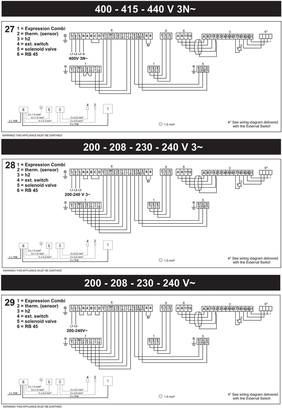
4 ild Kopplingsscheman. Kontrollera på aggregatets dataskylt att det ansluts till rätt spänning. Glöm inte att jorda! Ovanliga spänningar eller fas-tal. Vid inkoppling till andra spänningar eller fas-tal, som inte anges i ovanstående kopplingsscheman, kontakta Tylö Kundservice. Placering av termistor (sensor). Monteras 300mm från tak på vägg mellan inluft och utluft (ej ovanför bastuaggregatet). Termistorledningen kan förlängas utanför bastun med skärmad svagströmsledning (2-ledare). Tips! Termometern i bastun placeras på sådan höjd, att temperaturen överensstämmer med de exakta siffror H2 visar. OS! Täta eventuellt hål i väggen bakom termistorn. badformen och den de flesta förknippar med begreppet traditionella bastubad. Viktigt! nvänd vanligt dricksvatten - salt eller bräckt vatten skadar värmeelementen. Spola aldrig vatten på eller i aggregatet. adkastning skall ske med skopa på stenarna. nordningar som ger kontinuerlig vattenbegjutning på bastuaggregatet är inte heller tillåtna. Vid eventuella problem kontakta inköpsstället. Eftertryck, helt eller delvis, är förbjudet utan Tylös skriftliga tillstånd. Rätt till ändringar i material, konstruktion och design förbehålls. Reläbox (R). Monteras utanför och på obegränsat avstånd från bastun. Reläboxen får inte placeras närmare än 1 meter från H2. Skärmad svagströmsledning (6-ledare). Manöverledning H2 till reläbox skall vara skärmad svagströmsledning (6-ledare). Skärmningen ansluts till plint 12 i reläboxen. elysning. nslut belysningen enligt kopplingschema. Tillval: externbrytare Det finns möjlighet att ansluta en externbrytare till manöverpanelen. Se kopplingsschema som medföljer externbrytaren (rt.nr ). Momentan slutning: rytaren fungerar som av/på för varje tryck. Konstant slutning: Panelen går så länge slutning finns dock aldrig längre än inställd drifttid. När aggregatet är på kommer indikeringslampan i externbrytaren att lysa. Om panelen är programmerad för senare start blinkar indikeringslampan. DREGLER Duscha alltid innan du går in i bastun. Tag med dig en handduk att sitta på inne i basturummet. Stanna så länge du tycker att det är skönt, av och till går du ut och svalkar dig med en uppfriskande dusch. Visa hänsyn mot andra bastubadare. ada inte i högre temperaturer än att alla kan uppskatta det. Små barn tycker också om att bada bastu. Låt dem plaska med en balja vatten nere vid golvet eller nedre laven, där temperaturen är låg, men håll dem under uppsikt. vsluta alla bastubad med en lång sval dusch. Klä aldrig på dig direkt efter bastubadet, då börjar du svettas på nytt. Sitt kvar naken utanför bastun och koppla av, njut en kall dryck och känn hur gott du mår! Klä på dig först när kroppen har blivit avkyld och hudens porer tillslutna. Traditionella bastubad - torrbastu och våtbastu - kan du bada med alla Tylö bastuaggregat. Torrbastu och våtbastu är badformer som har sitt ursprung långt tillbaka i historien. Dessa heta bastubad njuts bäst i temperaturer mellan C. Vid torra bastubad förekommer ingen vattenbegjutning av stenmagasinet och den relativa luftfuktigheten (RH) är endast 5-10%. Våtbastu får du genom badkastning - då och då öser du en skopa vatten över de heta stenarna, luftfuktigheten ökar markant (RH 10-25%) - du känner hur värmevågorna vibrerar i luften och bearbetar huden. Några droppar Tylö astudoft i vattnet som du häller på stenarna, ger en uppfriskande och behaglig känsla i näsa och luftrör. Prova gärna att avsluta bastubadet med en intensivare badkastning som sticker till litet extra på kroppen. Våtbastu är den populäraste 4

5 WRNING! Make sure that there are no non-unsuitable object on top of the heater or in the sauna room before starting the sauna heater. Do not cover the sauna heater. This creates a fire hazard. Do not touch the top of the heater. This will cause severe burns. Incorrect ventilation or an incorrectly located sauna heater can, under certain circumstances, cause excessive drying of the wood in the sauna and create a fire hazard. Cover sauna floors with a non-slip material. Never hose down the sauna. There must always be at least 50 mm insulation directly behind the wood panelling in the sauna (no other material may be used, such as particle board, plaster, etc). Sauna doors must always open outwards. ll that should be needed to open the sauna door is just a little light pressure. Do not use the sauna for any purpose other than sauna bathing. Do not install more than one sauna heater in a sauna room, unless you follow exactly the special instructions for twin-heater installations. Sauna fragrances, etc. may ignite if poured undiluted into the stone compartment. Never leave young children unattended in the sauna. Sauna bathing is not always suitable for persons in poor health. Consult your doctor for advice. Store this information in a safe place. INSTLLTION Fig. 1. Sauna heater Tylö Expression with separate control panel H2 Expresssion is a floor standing heater Installing the sauna heater. Pic 2 - How to remove the front cover Slide the front cover upwards. Lift of the outer cover to access the electrical connection. Pic 3 - Mounting feet. Place the heater in the bottom part of the packaging. Mount the four adjustable feet underneath Pic 4, 5 - Electrical connection Leave the heater in the packaging with the front facing uppwards to facilitate the installation of electrical wiring. The packaging also protects the back cover from scrathes. Losen the screws and open the hatch The sauna heater should be placed on the same wall as the air inlet, see figure 16. Observing the regulations for the minimum distance to the side wall. Volume and minimum installation distances: kw Sauna volume min/max m³ Min. distance from side wall (mm) standard recess installation installation X Y Minimum distance to rear wall (mm). Minimum ceiling height in sauna (mm) *) Saunas with a heater installed in a recess must have a minimum volume of 4 cu.m. Tylö sauna heaters are connected by a standard cable (Fk or EKK) approved for permanent installation. The cable (EKK) or conduit is laid on the outside of any heating insulation; see figs. 12, 13 and 14. single-core cable (Fk) should be protected by a plastic conduit up to the heater, or in flexible metal conduit with internal insulation. Fig. 6 - Silicone. To make sure the unit is firmly in place silicon shall be applied at the specified contact surface (fig. 6) under the feet. Fig. 7 - Water Connect water and drain. oth pipes can be used either as water/drain depending on where it's located. Fig. 8 - Manual drain The alternative for the automatic emptying function is to manually empty the tank. In step 7, where water and sewer are connected, replace the connection to the sewer with the supplied ball valve. The package also includes a nipple that can be added for the connection of a hose if you like. When done, replace the frontcover (fig. 9) Fig Descaling When descaling, you remove the top stones and unscrew the four screws holding the grill in place. Lift off the grill to access the descaling pipe Fig Descaling Mix descaler and water as directed. Empty the tank manually or at the next automatic drain. Fig. 12 Minimum safety distances. = standard installation. = recess installation. Please refer to the table for minimum distances to side wall (X,Y). Minimum distance to rear wall is 100mm. When installing Expression sauna heater in a recess, the sensor (C) should be placed 250 mm from the rear wall of the recess and 300mm below the ceiling. Fig. 13 Minimum safety distances. Minimum distance to sauna fittings in front of a sauna heater. Fig. 14 Sauna (Sauna heater type Expression and control panel type H2). 1 = sauna heater. 2 = thermistor (sensor). 3 = control panel H2. 4 = external power switch (if any). 5 = distribution box. 6 = relay box R45. 7= Solenoid valve box Wiring diagram see fig. 27 Fig. 15 Sauna (Sauna heater type Expression and control panel type H2). 1 = sauna heater. 2 = thermistor (sensor). 3 = control panel H2. 4 = external power switch (if any). 5 = distribution box. 6 = relay box R45. 7= Solenoid valve box Wiring diagram see fig. 27 Fig. 16,17 Expression + H2. = electric conduit. = wooden panel. C = insulation behind control panel. D = sensor. E = capillary tube/thermistor wire. F = separate control panel H2. G = vent. mperage and conductor area: kw V 3~ V~ V 3~ V 2N~ V~ V 3~ amp mm² amp mm² amp mm² amp mm² amp mm² amp mm² * 16* 16 2, Control panel H2 Instructions: included with the control panel. Manual and automatic on/off. maximum of 24 hours' running time, 24 hours' pre-set time. Control panel type H2 is electronically controlled, and can have a remote control at one or more locations. The control cable between the sauna heater and the control panel must be a shielded cable (LiYCY). Connect the shielding to plinth 12 in the H2, see the wiring diagram. lternative placement The control panel is mounted on the wall inside the sauna room, no more than 760 mm above floor level (fig. 16) or outside the sauna at any distance from it (fig. 17). 6

6 UILDING INSTRUCTIONS The importance of correct sauna ventilation. Incorrect sauna ventilation can result in hot floors and benches, scorched walls and ceilings (the temperature limit control is triggered)! So we do urge you to follow our instructions for sauna ventilation carefully. djust the air outlet to evacuate 6 8 cu.m. of air per person, per hour, when the sauna is in operation. Mechanical sauna ventilation is not to be recommended, as the forced air supply can cause a fire hazard through the wooden panelling drying out. Fig. 18,19 Inlet vent always directly below the heater. The inlet vent should be driven straight through the wall directly below the centre of the heater. The cross-section of the vent for a family sauna is approx. 125 Sq.cm., for larger saunas approx. 300 sq.cm. Fig. 20 The outlet vent should never discharge directly into the open air. Position the air inlet and outlet vents as far away from one another as possible (diagonally opposite). The outlet vent should be located high on a wall or in the ceiling, and should have the same cross-section area as the inlet vent. Spent air should always be led back into the same room from which it is drawn into the sauna it must never be discharged directly into the open air. In this way, the air flowing from the sauna is continually being replenished in the room outside. This thermal ventilation method always works, no matter whether the pressure in adjacent rooms is negative or positive. If there is a gap above the sauna ceiling, do not seal it. To ventilate a cavity above the sauna, drill or cut at least one ventilation hole into the cavity through the wall on which the sauna door is located. lt. : Outlet vent through the sauna wall (seen from above). The vent is placed high up, near the ceiling. lt. : Outlet vent through the cavity above the sauna ceiling (seen from the side). lt. C: Outlet vent through a drum under the ceiling in the sauna (seen from the side). The outlet duct should be placed at an angle between the ceiling and the wall. The drum can be built of wooden panelling and have the same area as the outlet vent. Fig Solenoid valve box From the factory, the valves for emptying and refilling are assembled as in fig. 21a. If the placement of sewer and water connection is different, this is easily changeable. egin by removing the valves from the tracks they are located in (Fig. 21b). The bottom valve needs to be adjusted before both valves are fitted back. This is done by loosening the two screws shown in the picture and rotate the top of the valve half a turn (Fig. 21c). Unscrew the two screws and place both valves in the grooves. Now, the direction of emptying and filling have changed. Fig. 22 Recommendations for sauna construction:. Floor frame, corner posts, studs, ceiling frame.. attens, rafters, vents. C. 50 mm mineral wool as heat insulation, approx. 20 mm air gap between insulation and outer wall. D. 12 mm wooden panel in walls and ceilings. There should always be at least 50 mm of insulation behind the wooden panel; no other material, such as particle board or plaster, may be used. E. onded, non-slip plastic floor-covering, extending approx. 50 mm up the walls behind the wooden panelling. F. Inlet vents should always be fully open. May be fitted with a shuttered vent on the outside. G. Outlet vent, can be fitted with a sliding hatch to adjust through-flow. H. enches of at least 22 mm thick knot-free pine (alternatively aspen, lime or obeche). I. Drainage channel (recommended in public saunas). Never place a drainage channel or drain under the sauna heater. Fig. 23 Heater guard. The stones and the top of the sauna heater get very hot! In order to reduce the risk of accidental contact, Tylö always recommend that a heater guard be fixed as shown in the sketches. Some words of advice: There should never be a drain in a sauna. However, all public saunas should have a drainage channel (I, fig. 19) connected to a drain out-side the sauna (no drainage channel is needed in a private sauna). If the sauna has a window in the door or wall, treat the lower moulding with boat varnish and seal the joint between the glass and the moulding with a water-resistant silicone sealant. This prevents any condensation on the glass from seeping into the wood. Varnish the threshold and door handles a few times with boat varnish to maintain the finish and simplify cleaning the sauna. enches, decorative edging and back supports should be oiled on both sides with Tylö sauna oil (this is particularly important in the Tylarium). Note: ll other wood in the sauna should be untreated. Install floor decking only if the floor is slippery. Floor decking is impractical and prolongs the drying time for any water spilt on the floor. Treat the bucket and ladle with boat varnish, or oil them with Tylö sauna oil. The bucket will remain watertight and the wood will be beautifully preserved. Never leave the wooden bucket in the sauna after a sauna bath. efore you enjoy your first sauna bath, heat the sauna room up to 90 C and leave the heater to run for about 1 hour. This will rid the room of that new smell. Clean your sauna regularly. Scrub the benches and floor with soft soap. It is a mild, gentle detergent and leaves a pleasant fragrance. General Information Fig. 24. Filling the stone compartment. Only use stones of the dolerite type (Tylö sauna stones), as ordinary stones can damage the unit. Fill the stone compartment around the elements from bottom to top, stacking the stones approx. 50 mm above the front edge at the top of the unit. Do not press the stones into place. Fig. 25. Never place stones above the side air chambers. This prevents air circulation, the unit becomes overheated and the temperature limit control is triggered. Check the stone compartment at least once a year. This is especially important for public saunas and saunas in frequent use. Remove all stones from the compartment. Clean any small stones, grit, gravel and chalky deposits from the bottom of the stone compartment. Use only stones which are whole and intact, replacing them when necessary with new dolerite stones. Temperature limit control. Tylö sauna heaters have a temperature limit control built into the terminal box on the heater. This is activated automatically if there is any risk of overheating. More often than not, the cut-off is triggered because of incorrect sauna ventilation or an incorrectly located sauna heater. Call an expert to reset the temperature limit control. Fig. 26. Sprinkling water on the stones Must always be done with a ladle onto the stones, never with a hose or bucket. Note: The stones must be hot. Fragrant sauna bath can be obtained by using fragrances. Splash a few drops of essence in the fragrance dispenser. In order to obtain a pleasant because moisture in the sauna fill the internal humidifier with water before the sauna is switched on.. Fragrance dispenser. Humidifier If neccessary, clean fragrance dispenser and humidifier. Lift it off and rinse under running water. 7

7 Figs Wiring diagrams. Check the heater s type identification plate to ensure that the heater is connected to the right voltage. Don t forget The installation must be earthed! Placement of the thermistor (sensor). Must be placed 300mm below ceiling on the wall between air inlet and outlet (not above the sauna heater). The thermistor wire can be lengthened outside of the sauna with a partially enclosed low-voltage cable (2-core). The thermometer in the sauna should be placed at a height so that the temperature corresponds exactly to the numbers displayed on the CC 50/CC 100/ CC 300/ H2. Note: If necessary seal the hole in the wall behind the thermistor. Relay box (R). (No relay box is used for SE and MPE heaters). Installed outside the sauna at any distance from it. The relay box may not be placed closer than one metre from the CC 10/ CC 50/ CC 100/ CC 300/ H2. Partially enclosed low-voltage cable (6-core). The control cable between the CC/H2/EC50 and the relay box must be a partially enclosed low-voltage cable (6-core). Connect the shielding cable to plinth 12 in the relay box. Lighting. Connect the lighting according to the wiring diagram. In dry saunas, where the stones are not sprinkled with water, the relative humidity (RH) is as low as 5 10%. In wet saunas, when water is ladled on the hot stones from time to time, the relative humidity rises steeply to 10 25%, and you can feel how the quivering waves of heat massage their way into your skin. few drops of Tylö Sauna Fragrance added to the water poured over the stones give a pleasantly invigorating sensation, clearing nasal cavities and helping you breathe more easily. great way to round off any sauna is to experience the pleasant tingling sensation when you pour a little extra water over the stones. Wet saunas are considered by most people to be the traditional way to enjoy a sauna, and they are the most popular too. Important! Use ordinary drinking water. Salt-water, swimming pool or spa water will damage the heating elements. Never hose down the heater. Water sprinkling must always be done with a ladle onte the stones. Devices that provide continuous water sprinkling are not permissible. In the event of any problems, please contact the retailer where you purchased the equipment. This publication many not be reproduced, in part or in whole, without the written permission of Tylö. Tylö reserves the right to make changes in materials, construction and design. Remote control operation. CC/H2 control panels are already prepared for remote-control operation from one or more locations. Option: external on/off-switch. It is possible to connect an optional external switch to the H2 panel. See wiring diagram delivered with the external switch (rt.no ). Momentary connection: switches on and off respectively each time it is pressed. Constant connection: the panel is activated for as long as the connection is maintained, up to the maximum running time that has been set. When the heater is on, the indicator lamp on the external switch lights up. If the panel has been programmed to start at a later time, the indicator lamp flashes. Unusual voltages or number of phases. efore connecting the heater to a different voltage or number of phases than those described in the wiring diagram, contact Tylö Customer Service. HOW TO GET THE MOST OUT OF YOUR SUN lways shower before going into the sauna. Take a towel in with you to sit on. Stay inside the sauna only as long as it feels pleasant. Go out now and then to cool off and freshen up with a quick shower. Show consideration for other bathers. Don t set the temperature higher than is pleasant for all those using the sauna. Young children love saunas. Let them splash about in a tub of water on the floor or the lower benches where it is somewhat cooler. ut remember to keep an eye on them at all times. Round off your sauna with a long, cool shower. Never get dressed right after your sauna. This will only cause you to perspire. Relax, treat yourself to a cold drink and enjoy a sensation of true well-being. Don t get dressed until your body has cooled down and your pores have closed once again. You can enjoy traditional dry and wet saunas with provide continuous water sprinkling are not permissible. You can enjoy traditional dry and wet saunas with all Tylö heaters. Dry and wet saunas are bathing forms whose history is shrouded in the mists of time. These hot baths are best enjoyed at temperatures between 70ºC and 90ºC. 8

8 SILICONE Vatten in Water in Vatten ut Water out 7 8 lt

9 9 10 2:1 H 2 O SOLVENT/ SULFMIC H 2 O+ SOLVENT/ SULFMIC 11 X Min. 100 mm Max. 250 mm Y C Y Max mm = min. 400mm = min. 200mm Min. 20 mm 12 13

10 50-150cm 300mm cm mm Max 760 mm Max 70mm Max 70mm mm D E C F 18 F 19 Max 760 mm G C 20

11 21a 21b V V 21c 21d e V V

12 C D G F E Sauna I H 22 lt = min. 200 mm lt = min. 400 mm Max 400 mm Min 20 mm

13
14 Connection placements Expression Combi 10kW Water in/out Water in/out Electrical wiring Seen from below

15 Viewed from the front

INSTALLATIONSANVISNING SENSE SPORT
 3 SVENSKA INSTALLATIONSANVISNING SENSE SPORT 900575-SVE INNEHÅLL Före installation... Delar... Krav för installation... Verktyg för installation... Planering av installation... Installation... 3 Installation
INSTALLATIONSANVISNING SENSE SK
 0 SVENSKA INSTALLATIONSANVISNING SENSE SK 90050-SVE INNEHÅLL Före installation... Delar... Krav för installation... Verktyg för installation... Planering av installation... Installation... Installation
INSTALLATIONSANVISNING SENSE PLUS
 05 SVENSKA INSTALLATIONSANVISNING SENSE PLUS 900550-SVE INNEHÅLL Före installation... Delar... Krav för installation... Verktyg för installation... Planering av installation... Installation... 4 Installation
Technical description with installation and maintenance instructions
 www.euronom.se Technical description with installation and maintenance instructions VPS 300 / 500 BXU 0710-102 EXOTANK VPS 300/500 BXU Technical description Installation and maintenance instructions Installation...2
Windlass Control Panel v1.0.1
 SIDE-POWER Windlass Systems 86-08950 Windlass Control Panel v1.0.1 EN Installation manual Behåll denna manual ombord! S Installations manual SLEIPNER AB Kilegatan 1 452 33 Strömstad Sverige Tel: +46 525
Boiler with heatpump / Värmepumpsberedare
 Boiler with heatpump / Värmepumpsberedare QUICK START GUIDE / SNABBSTART GUIDE More information and instruction videos on our homepage www.indol.se Mer information och instruktionsvideos på vår hemsida
Monteringsanvisning Podie T 4100 K
 Monteringsanvisning Podie T 4100 K Monteringsanvisning Förbered fundamentet 1. Montera ställfötterna. Montera tvättmaskin SV 1. Fäst gaffelbeslagen i bakkant med brickor och skruv. OBS! Placera beslagen
Storlek/ Size. Modell/ Model. Effekt/ Effect. Vattenmängd/ Water amount T30 63W T30 87W T30 67W T30 76W T30 108W T30 121W
 HANDDUKSTORK 101641 HANDDUKSTORK Glow 110/260 95 65/205 CC Shine 400/500 80 345/445 CC 750/1200 40 117 41 630/1080 CC Joy 500 80 445 CC 100 690/1000/1400 540/850/1250 CC 78 27 1200 1140 CC x2 101659x1
Expression. Art.nr
 Expression rt.nr 900 60 070 IP4 Installations- och bruksanvisning......... Svenska sid. Inkoppling skall utföras av behörig el-installatör. SPR NVISNINEN! Efter installation överlämnas denna till bastuns
VASSVIK FIXED STAND SE / ENG
 VASSVIK FIXED STAND SE / ENG SE VIKTIGT Läs noga igenom instruktionerna före användning och spar dessa för framtida bruk. VARNING: Barnets huvud bör inte ligga lägre än barnets kropp. Lägg inte till ytterligare
BBT057/ BBC057 BBCD057/ BBT057-NL HOLDEN COLORADO 9/2016+ HOLDEN TRAILBLAZER WD & 4WD Models
 INSTALLATION GUIDE BBT057/ BBC057 BBCD057/ BBT057-NL HOLDEN COLORADO 9/2016+ HOLDEN TRAILBLAZER 2017+ 2WD & 4WD Models Ironman 4x4 BBT/ BBC/ BBCD/BBT057-NL Bull Bars fit to a Holden Colorado 9/2016+ It
P650 - Takscreen. Installationsguide EN
 P650 - Takscreen Installationsguide 1309-150507EN V650-Tallinn Installation manual Montera främre linhjul 12 13 Placera linan över linhjulet och skruva tillbaka täcklocket på linhjulhuset (7). Öppna linhjulshuset
VARIOBARRIER S/M MIMSAFE BY CHOICE
 VAROBARRR S/M MMSA BY CHOC K L A B D M C H A B C D 522 K 524 Right leg Right leg 514L 514R 510L 510R L 526L M 526R S508 S509 521 6X 521 + H 527 529 528 8X/1 18X 8X/1 M-460641AL M-SM6X14A M-460641B M-M37202_2014
PRESS FÄLLKONSTRUKTION FOLDING INSTRUCTIONS
 PRESS FÄLLKONSTRUKTION FOLDING INSTRUCTIONS Vänd bordet upp och ner eller ställ det på långsidan. Tryck ner vid PRESS och fäll benen samtidigt. OBS! INGA STORA KRAFTER KRÄVS!! Om benen sitter i spänn tryck
Plain A262. För T16 (T5) lysrör. Innehåll. Monteringsanvisning. A. Instruktion för rampmontering
 lysrör. Innehåll. Monteringsanvisning. A. Instruktion för rampmontering") Plain A262 För T16 (T5) lysrör Innehåll Ramparmatur: ändmodul En stängd gavel/ en öppen gavel Plint i båda ändarna Överkopplingssladd 1 rampgavel 1 lysrörsbytare Ramparmatur: mellanmodul Plint i en ände
Plain A262 För T16 (T5) lysrör Innehåll Ramparmatur: ändmodul En stängd gavel/ en öppen gavel Plint i båda ändarna Överkopplingssladd 1 rampgavel 1 lysrörsbytare Ramparmatur: mellanmodul Plint i en ände
Montageanvisning Airway system 1000/1500 Assembly instruction Airway system 1000/1500
 S.Det är lämpligt att denna information överlämnas till användaren av anläggningen. GB. It is appropriate that this information is passed on to the user of the installation. D. Diese informationen sind
ASSEMBLY INSTRUCTIONS SCALE SQUARE - STANDARD
 ASSEMBLY INSTRUCTIONS ALL COMPONENTS Metal profile 0 mm Gripper Ceiling attachments Screws for ceiling attachements (not included) Wires Metal profile 60 mm Metal profile 00 mm Felt - Full Felt - Half
Nathi Skötbord Changing unit Table à langer murale Wickeltisch Verschoontafel Puslebord Cambiador de pared Přebalovací pult Fasciatoio
 Nathi Skötbord Changing unit Table à langer murale Wickeltisch Verschoontafel Puslebord Cambiador de pared Přebalovací pult Fasciatoio Пеленальный стол Tested and approved according to SS-EN 12221:2008+A1_2013
LINC MODELL 13. INR SVERIGE AB Kosterögatan 15 SE-211 24 Malmö 13 EN 1428:2005+A1:2008
 LINC MODELL 13 151005 Produkten är anpassad till branschregler Säker Vatteninstallation. INR garanterar produktens funktion om branschreglerna och monteringsanvisningen följs. INR SVERIGE AB Kosterögatan
HUR DU BYGGER BASTU. Version 001
 090922 HUR DU BYGGER BASTU Version 001 Hur du bygger bastu.pdf Version 001 090922 Bra att veta om bastubygge, installation och ventilation. Att bygga en bastu bräda för bräda med regelverk, isolering,
TYLÖ SAUNA HARMONY PRO
 TYLÖ SAUNA HARMONY PRO 2017-01-12 Art.nr 2900 4708 Väggsektion för aggregat Wall section for heater Moduł ścianki do montażu pieca do sauny Information Ø 30 Tips! Tip! Porada! Information Rumsemballage
ASSEMBLY INSTRUCTIONS SCALE - SYSTEM
 ASSEMBLY INSTRUCTIONS 60 mm 00 mm 600 mm 000 mm R50 mm ALL COMPONENTS Metal profile 60 mm (start and end of system) Metal profile connection Wire Felt square Metal profile 00 mm Metal profile connection
ASSEMBLY INSTRUCTIONS SCALE CIRCLE - STANDARD
 ASSEMBLY INSTRUCTIONS ALL COMPONENTS Metal profile 0 mm Gripper Ceiling attachments Screws for ceiling attachements (not included) Wires Metal profile 60 mm Metal profile 00 mm Felt - Full Felt - Half
GOLD SD 14-40. Med styrenhet/with control unit. Fläkt/ Fan. Utan filter/ Without filter. Fläkt/Fan. Fläkt/ Fan. Med filter/ With filter.
 GOLD SD 4-40 Med styrenhet/with control unit Skiss visar styrenhet för aggregat med inspektionssida vänster, styrenhet för aggregat med inspektionssida höger ser något annorlunda ut, men principen är lika./
BATH MIXER 160 LINC 21. incl. HAND SHOWER. inr.se
 LINC 21 BATH MIXER 150 BATH MIXER 160 incl. HAND SHOWER 110309 inr.se Innan montering Vi förordar en sakkunnig VVS-installatör vid installation och service. Ledningarna ska renspolas innan installation.
Support Manual HoistLocatel Electronic Locks
 Support Manual HoistLocatel Electronic Locks 1. S70, Create a Terminating Card for Cards Terminating Card 2. Select the card you want to block, look among Card No. Then click on the single arrow pointing
Installation Instructions
 Installation Instructions (Cat. No. 1794-IE8 Series B) This module mounts on a 1794 terminal base unit. 1. Rotate keyswitch (1) on terminal base unit (2) clockwise to position 3 as required for this type
IRAB Mottagare sida 2-5 Tele Radio AB Mottagare sida 6
 IRAB Mottagare sida -5 Tele Radio AB Mottagare sida 6 Installation of receiver type smd 700 4 RELAY FUNCTIONS / -4 VAC/DC PCB TYPE NO: LWEG 4L Rev: 95-09 Installation: Install the receivers in a protected
GOLD SD 50-80. Fläkt 2/ Fan 2. Fläkt 1/ Fan 1. Fläkt/ Fan. Utan filter/ Without filter. Fläkt 1/ Fan 1. Fläkt 2/ Fan 2. Med filter/ With filter Filter
 SE/G.ELSD5080.0803 GOLD SD 50-80 Med styrenhet/with control unit Skiss visar styrenhet för aggregat med inspektionssida vänster, styrenhet för aggregat med inspektionssida höger ser något annorlunda ut,
Monteringsanvisning benfundament TM 8055, TM 8060, T 8118 K. Art nr ,
 Monteringsanvisning benfundament TM 8055, TM 8060, T 8118 K Art nr 102056, 102057 Monteringsanvisning Förbered fundamentet 1. Montera ställfötterna. Montera tvättmaskin SV 1. Fäst gaffelbeslagen i bakkant
BRUKSANVISNING SENSE SPORT
 1311 SVENSKA BRUKSANVISNING SENSE SPORT 29005175-SVE INNEHÅLL Allmän information... 1 Före användning... 1 Första gången du använder aggregatet...1 Före varje användning... 2 Användning...2 Temperaturinställning...
ARC 32. Tvättställsblandare/Basin Mixer. inr.se
 ARC 32 Tvättställsblandare/Basin Mixer inr.se SE Användning och skötsel Manualen är en del av produkten. Bevara den under hela produktens livscykel. Vi rekommenderar er att noggrant läsa igenom manualen
Monteringsanvisning Nödutrymningsbeslag ASSA 179E
 Monteringsanvisning Nödutrymningsbeslag ASSA 179E Denna monteringsanvisning avser nödutrymningsbeslag ASSA 179E med artikelnummer 364371 i kombination med låshus Abloy EL580 med artikelnummer EL580100011.
Bruksanvisning Directions for use
 Bruksanvisning Directions for use KOMBIDON OUTSIDE WALL HOOD SVENSK/ENGLISH VERSION SVENSKA Denna montageanvisning omfattar produkten KOMBIDON. BESKRIVNING/ ANVÄNDNING Kombidon från AB C.A. Östberg är
INSTALLATIONSANVISNING SENSE COMBI
 SVENSKA INSTALLATIONSANVISNING SENSE COMBI 900595-SVE INNEHÅLL Före installation... Delar... Krav för installation... Verktyg för installation... Planering av installation... Installation... 4 Installation
MCP-16RC, Air Purification
 Kompakt patronfilter med tryckstötsrensning. MCP-16RC Air Purification Tower är ett kompakt patronfilter för decentraliserad luftrening inomhus, där luft återåtervinning är möjlig. Den kompakta filterenheten
Accepterad monteringsanvisning 2016:1. Metris (RSK: ) Metris S (RSK: ) Metris (RSK: )
 Metris S (RSK: ) Metris (RSK: )") EN Table of contents 1 Instructions for use / assembly instructions 2 Assembly 4-5 Adjustment 6 Operation 7 Dimensions 8-9 Flow diagram 8-9 Spare parts 10-12 Cleaning 13 Test certificate 14 Contact information
EN Table of contents 1 Instructions for use / assembly instructions 2 Assembly 4-5 Adjustment 6 Operation 7 Dimensions 8-9 Flow diagram 8-9 Spare parts 10-12 Cleaning 13 Test certificate 14 Contact information
INDUKTIV SLINGDETEKTOR INDUCTIVE LOOP DETECTOR
 INDUKTIV SLINGDETEKTOR INDUCTIVE LOOP DETECTOR Slingdetektorn används som ett alternativ till mekaniska gränslägen, momentbrytare eller annat gränsläge i gödselrännor. Detektorn är kopplad till en trådslinga
GOLD SD 80-2. Med styrenhet/with control unit. Fläkt 1A/B/ Fan 1A/B. Fläkt 2A/B/ Fan 2A/B. Fläkt/ Fan. Utan filter/ Without filter
 SE/G.ELS80E.3095 GOL S 80- Med styrenhet/with control unit Skiss visar styrenhet för vänster, styrenhet för höger ser något annorlunda ut, men principen är lika./ The sketch shows control unit for HU with
Montageanvisning Airway system 1000/1500 Assembly instruction Airway system 1000/1500
 S.Det är lämpligt att denna information överlämnas till användaren av anläggningen. GB. It is appropriate that this information is passed on to the user of the installation. D. Diese informationen sind
Monteringsanvisning benfundament TM 9060, TM 9070, T 9153 E/K/VP. Art nr , ,
 Monteringsanvisning benfundament TM 9060, TM 9070, T 9153 E/K/VP Art nr 102058, 102059, 102030 Monteringsanvisning SV Förbered fundamentet 1. Montera ställfötterna. 4. Fundamentet skall alltid tippsäkras.
Svenska()(Bruksanvisning(för(handdukstork()(1400(x(250(mm(
(Bruksanvisning(för(handdukstork()(1400(x(250(mm(") 1 Svenska()(Bruksanvisning(för(handdukstork()(1400(x(250(mm( Läsnogaigenombruksanvisningeninnanproduktenanvänds 6Kontrolleraattduharalladelarenligtpacklistannedan.Kontaktadinåterförsäljareomnågondelär
1 Svenska()(Bruksanvisning(för(handdukstork()(1400(x(250(mm( Läsnogaigenombruksanvisningeninnanproduktenanvänds 6Kontrolleraattduharalladelarenligtpacklistannedan.Kontaktadinåterförsäljareomnågondelär
PRESS FÄLLKONSTRUKTION FOLDING INSTRUCTIONS
 PRESS FÄLLKONSTRUKTION FOLDING INSTRUCTIONS Vänd bordet upp och ner eller ställ det på långsidan. Tryck ner vid PRESS och fäll benen samtidigt. Om benen sitter i spänn tryck benen mot kortsidan före de
TYLÖ SAUNA EVOLVE CORNER TRADITION
 TYLÖ SAUNA EVOLVE CORNER TRADITION 1507 Art.nr 2900 4225 Väggsektion för aggregat Wall section for heater Moduł ścianki do montażu pieca do sauny Tips! Tip! Porada! Rumsemballage Använd som skydd på golvet
BRUKSANVISNING SENSE PLUS
 1205 SVENSKA BRUKSANVISNING SENSE PLUS 29005151-SVE INNEHÅLL Allmän information... 1 Före användning... 1 Första gången du använder aggregatet...1 Före varje användning... 2 Användning...3 Funktioner...
Installation. Twice Nisch. Twice Corner SVENSKA ENGLISH
 Installation Arrow Skandinavien AB Tel: +46 (0)31 330 00 10 www.arrowshower.com Twice Corner Twice Nisch SVENSKA (SV) Installationsanvisning för Arrow duschvägg. Vi förbättrar ständigt våra installationsanvisningar.
Accepterad monteringsanvisning 2016:1. Talis S (RSK: ) Talis S 100 CoolStart (RSK: )
 Talis S 100 CoolStart (RSK: )") EN Table of contents 1 Instructions for use / assembly instructions 2 Assembly 4-5 Adjustment 6 Dimensions 7 Flow diagram 7 Operation 8 Spare parts 9 Cleaning 10 Test certificate 11 Contact information
EN Table of contents 1 Instructions for use / assembly instructions 2 Assembly 4-5 Adjustment 6 Dimensions 7 Flow diagram 7 Operation 8 Spare parts 9 Cleaning 10 Test certificate 11 Contact information
DAMPER EQAZ-12, EQAZ-13, STAZ-30, STBZ-30
 DAMPER EQAZ-12, EQAZ-13, STAZ-30, INSTALLATION INSTRUCTION EQAZ-12 DAMPER, DAMPER ACTUATOR AND EQAZ-13LEVER ACTUATOR DAMPER ACTUATION The damper can be actuated by means of the, damper actuator (accessory)
SAFETY PRECAUTIONS SPECIFICATIONS
 SAFETY PRECAUTIONS Read the instructions carefully before use and save them for future reference. Before you connect the appliance: Ensure that the voltage rating on the type plate corresponds to your
 BÄNKVÅG / BENCH SCALE Modell : SW-III / Model : SW-III ANVÄNDARMANUAL / USER MANUAL SW-III WWW.LIDEN-WEIGHING.SE 2014-03-26 OBS! Under vågen sitter en justerbar skruv (se bild). Standardinställning är
Accepterad monteringsanvisning 2016:1
 EN Table of contents 1 Instructions for use / assembly instructions 2 Assembly 4-6 Adjustment 7 Dimensions 8 Flow diagram 9 Test certificate 9 Operation 10 Spare parts 11 Cleaning 12 Contact information
 BÄNKVÅG / BENCH SCALE ANVÄNDARMANUAL / USER MANUAL SW-III www.liden-weighing.com Svenska OBS! Under vågen sitter en justerbar skruv (se bild). Standardinställning är den för vägning. Om ni vill rengöra
This manual should be saved! EcoFlush Manual. Wostman 2018:2
 This manual should be saved! EcoFlush Manual Wostman 2018:2 ENGLISH Important! This manual should be saved by the owner! It s important to read the whole manual before installation. EcoFlush gives the
INSTALLATION INSTRUCTIONS
 INSTALLATION - REEIVER INSTALLATION INSTRUTIONS RT0 RF WIRELESS ROOM THERMOSTAT AND REEIVER MOUNTING OF WALL MOUTING PLATE - Unscrew the screws under the - Pack contains... Installation - Receiver... Mounting
Accepterad monteringsanvisning 2016:1. Ecos M CoolStart (RSK: ) Ecos L CoolStart (RSK: ) 1 (12)
 Ecos L CoolStart (RSK: ) 1 (12)") EN Table of contents 1 Instructions for use / assembly instructions 2 Assembly 4-5 Adjustment 6 Dimensions 7 Flow diagram 7 Operation 8 Spare parts 9 Cleaning 10 Test certificate 11 Contact information
EN Table of contents 1 Instructions for use / assembly instructions 2 Assembly 4-5 Adjustment 6 Dimensions 7 Flow diagram 7 Operation 8 Spare parts 9 Cleaning 10 Test certificate 11 Contact information
This manual should be saved! EcoFlush Manual
 This manual should be saved! EcoFlush Manual ENGLISH Important! This manual should be saved by the owner! Read the whole manual before installation. The flush volumes are factory set at 2.5 / 0.3 liters.
Anvisning för Guide for
 Anvisning för Guide for PRISMA SENSOR 1 96243235zPC Montering i tak/installation in the ceiling Byte av kupa/change of diffuser 2 Installation Installation från gavel / Installation from the end Installationskabel
INSTALLATIONSANVISNING SENSE COMBI
 0 SVENSKA INSTALLATIONSANVISNING SENSE COMBI 900560-SVE INNEHÅLL Före installation... Delar... Krav för installation... Verktyg för installation... Planering av installation... Installation... 4 Installation
Accepterad monteringsanvisning 2016:1. Talis S (RSK: ) Talis S (RSK: ) 1 (12)
 Talis S (RSK: ) 1 (12)") EN Table of contents 1 Instructions for use / assembly instructions 2 Assembly 4-5 Adjustment 6 Dimensions 7 Flow diagram 7 Operation 8 Spare parts 9 Cleaning 10 Test certificate 11 Contact information
EN Table of contents 1 Instructions for use / assembly instructions 2 Assembly 4-5 Adjustment 6 Dimensions 7 Flow diagram 7 Operation 8 Spare parts 9 Cleaning 10 Test certificate 11 Contact information
BBT042/ BBC042/ BBCD042 NISSAN NAVARA D40 V STX & PATHFINDER R WD & 4WD Models
 INSTALLATION GUIDE BBT042/ BBC042/ BBCD042 NISSAN NAVARA D40 V6 2010+ STX & PATHFINDER R51 2010+ 2WD & 4WD Models Ironman 4x4 BBT/ BBC/ BBCD042 Bull Bars fit to a Nissan Navara D40 STX & Pathfinder R51.
manual Facial spa Art nr: 48682 Rubicson 2016-06-08
 manual Facial spa Art nr: 8682 EN NO SV 2016-06-08 Rubicson ENGLISH Overview Use Fill the container ENGLISH 1. Make sure that the power cord is not connected to a wall socket. 1 2 2. Remove the funnel
Accepterad monteringsanvisning 2016:1. Focus (RSK: ) 1 (12)
 1 (12)") EN Table of contents 1 Instructions for use / assembly instructions 2 Assembly 4 Adjustment 5 Dimensions 6 Flow diagram 6 Operation 7 Spare parts 8 Cleaning 9 Test certificate 10 Contact information 12
EN Table of contents 1 Instructions for use / assembly instructions 2 Assembly 4 Adjustment 5 Dimensions 6 Flow diagram 6 Operation 7 Spare parts 8 Cleaning 9 Test certificate 10 Contact information 12
INKOPPLINGSANVISNING ELTRYCKSLÅS WIRING DIAGRAM SOLENOID LOCK
 INKOPPLINGSANVISNING ELTRYCKSLÅS WIRING DIAGRAM SOLENOID LOCK SE EN S. 2-4 P. 5-7 SL 510/511 SL 520/521 SL 530-50/531-50 2013 11 07 SE TEKNISK SPECIFIKATION Driftspänning. Ström. Reed relä. Drifttemperatur.
Installation Instruction Monteringsinstruktion JK400
 Installation Instruction Monteringsinstruktion JK400 Tools: 2pcs of spanner 13 and 17mm or 2pcs of adjustable spanner, cross slotted screwdriver PZ 2 Warning: Plates can be sharp in the edges and corners,
Accepterad monteringsanvisning 2016:1. Focus (RSK: ) Focus 100 CoolStart (RSK: ) (RSK: )
 Focus 100 CoolStart (RSK: ) (RSK: )") EN Table of contents 1 Instructions for use / assembly instructions 2 Assembly 4-5 Adjustment 6 Dimensions 7 Flow diagram 7 Operation 8 Spare parts 9-10 Cleaning 11 Test certificate 12 Contact information
EN Table of contents 1 Instructions for use / assembly instructions 2 Assembly 4-5 Adjustment 6 Dimensions 7 Flow diagram 7 Operation 8 Spare parts 9-10 Cleaning 11 Test certificate 12 Contact information
LINC 23. Tvättställsblandare/Basin Mixer. inr.se 130226A
 LINC 23 Tvättställsblandare/Basin Mixer 130226A inr.se S Användande och skötsel Manualen är en del av produkten. Bevara den under hela produktens livscykel. Vi rekommenderar att noggrant läsa igenom manualen
Monteringsanvisning Installation instructions
 Monteringsanvisning Installation instructions TAKGENOMFÖRING med överbeslag TGÖ/THÖ och underbeslag TGU ROOF CURB with mounting plate TGÖ/THÖ and bottom fixing plate TGU Denna bruksanvisning omfattar följande
(SV) Installationsmanual för duschkabiner och ångbastukabiner (EN) Installation manual for shower cabins and steam cabins
 Installationsmanual för duschkabiner och ångbastukabiner (EN) Installation manual for shower cabins and steam cabins") Arrow Skandinavien AB Tel: +46 (0)31 330 00 10 www.arrowshower.com (SV) Installationsmanual för duschkabiner och ångbastukabiner (EN) Installation manual for shower cabins and steam cabins 6030 6130 Ver:
Arrow Skandinavien AB Tel: +46 (0)31 330 00 10 www.arrowshower.com (SV) Installationsmanual för duschkabiner och ångbastukabiner (EN) Installation manual for shower cabins and steam cabins 6030 6130 Ver:
Discovery FSQ, IAA Utgåva/Edition 11. SE Habo. Klass 2 IAA FSQ-I 26W. 4 mm c c mm N L
 Discovery FQ, IAA E - 566 80 Habo 3 4 4 mm c c mm 5 IAA Klass FQ-I 6W För armatur klass II,eller armatur för IAA/FQ-I 6W skall medföljande skyddsslang användas. For luminaire of Class II,or luminaire for
LINC Modell 17 130624A
 LINC Modell 17 130624A Denna produkt är anpassad till Branschregler Säker Vatteninstallation. INR garanterar produktens funktion om branschregler och monteringsanvisning följs. INR SVERIGE AB Kosterögatan
FORTA M315. Installation. 218 mm.
 1 Installation 2 1 2 1 218 mm. 1 2 4 5 6 7 8 9 2 G, G0= Max 100 m 1.5 mm² (AWG 15) X1, MX, Y, VH, VC = Max 200 m 0.5 mm² (AWG 20) Y X1 MX VH VC G1 G0 G 0 V 24 V~ IN 0-10 0-5, 2-6 60 s OP O 1 2 4 5 6 7
Diskant Yta eller Vikelfäste montering Mount
 Installation och Bruksanvisning Inledning Välj fästpunkterna för dina dome TW250 Silk diskanter. Kom ihåg att för bästa prestanda bör diskanterna monteras så nära mitten av bas som möjligt, med fri, direkt
Accepterad monteringsanvisning 2016:1. Talis E ( ) ( ) Talis E 110 CoolStart ( )
 ( ) Talis E 110 CoolStart ( )") EN Table of contents 1 Instructions for use / assembly instructions 2 Assembly 4-6 Test certificate 6 Adjustment 7 Dimensions 8 Flow diagram 8 Operation 9 Spare parts 10-11 Cleaning 12 Contact information
EN Table of contents 1 Instructions for use / assembly instructions 2 Assembly 4-6 Test certificate 6 Adjustment 7 Dimensions 8 Flow diagram 8 Operation 9 Spare parts 10-11 Cleaning 12 Contact information
BBT014/ BBC014/ BBCD014 PJ & PK FORD RANGER WD & 4WD Models
 INSTALLATION GUIDE BBT014/ BBC014/ BBCD014 PJ & PK FORD RANGER 2007+ 2WD & 4WD Models Ironman 4x4 BBT/ BBC/ BBCD014 Bull Bars fit to a Ford Ranger. It will take about 3 hours to install. NOTE: This product
BRIC MODELL A
 BRIC MODELL 3 150123A 2,5 & 4mm 1 2a 3 4 x 2 x 2 5a 2b 6 5b 5c 5d 5e x 1 x 1 x 1 x 1 1 x 1 x 1 x 4 x 1 x 3 x 4 ~20mm Alternativ placering av mittenstöd. Alternative placement of centre support 75-95mm
Module 6: Integrals and applications
 Department of Mathematics SF65 Calculus Year 5/6 Module 6: Integrals and applications Sections 6. and 6.5 and Chapter 7 in Calculus by Adams and Essex. Three lectures, two tutorials and one seminar. Important
IMPORTANT! RETAIN FOR FUTURE REFERENCE PLEASE READ CAREFULLY VIKTIGT! BEHÅLL FÖR FRAMTIDA REFERENS LÄS IGENOM INSTRUKTIONSMANUALEN
 Heart & Stripes Junior Bed Instructions Manual Instruktions Manual IMPORTANT! RETAIN FOR FUTURE REFERENCE PLEASE READ CAREFULLY VIKTIGT! BEHÅLL FÖR FRAMTIDA REFERENS LÄS IGENOM INSTRUKTIONSMANUALEN Thank
SAFETY PRECAUTIONS SPECIFICATIONS
 SAFETY PRECAUTIONS Read the instructions carefully before use and save them for future reference. Before you connect the appliance: Ensure that the voltage rating on the type plate corresponds to your
Assembly instruction Kit 200
 MA9602 2012-11-19 1/2 S.Det är lämpligt att denna information Montageanvisning Kit 200 Assembly instruction Kit 200 Observera: För att IP44 ska packning och bricka användas vid installation enligt bild
Vanliga frågor om Duocom (för installatör eller reparatör) GB Frequently asked questions about Duocom (for installer or repairman)
 GB Frequently asked questions about Duocom (for installer or repairman)") Manual SE Vanliga frågor om Duocom (för installatör eller reparatör) GB Frequently asked questions about Duocom (for installer or repairman) 1 SE VANLIGA FRÅGOR OM DUCOM... 3 1.1 Det hörs inget ljud i
Manual SE Vanliga frågor om Duocom (för installatör eller reparatör) GB Frequently asked questions about Duocom (for installer or repairman) 1 SE VANLIGA FRÅGOR OM DUCOM... 3 1.1 Det hörs inget ljud i
Molift Raiser 75135G Etac Box 203, Anderstorp Sweden Tel Fax
 7G 8-0-07 SE SE EN EN Till och med serienummer 0900 Från serienummer 0900 Up to serial number 0900 From serial number 0900.... Etac Box 0, Anderstorp Sweden Tel + 7 8 7 00 Fax + 7 8 7 90 www.etac.com Svenska
LÄNKHJUL S3. Monteringsanvisning för: Länkhjul S3
 MONTERINGSANVISNING LÄNKHJUL S3 Art.no. 8822117 Rev.2018-01 Link to english Monteringsanvisning för: Länkhjul S3 art.nr. 2002010 Länkhjul S3 90 mm art.nr. 2002020 Länkhjul S3 120 mm art.nr. 2002030 Länkhjul
Rev No. Magnetic gripper 3
 Magnetic gripper 1 Magnetic gripper 2 Magnetic gripper 3 Magnetic gripper 4 Pneumatic switchable permanent magnet. A customized gripper designed to handle large objects in/out of press break/laser cutting
Slangupprullare Hose reels
 Slangupprullare Hose reels Slangupprullare Slangupprullare typ 888 För olja, fett, luft och vatten. Robust konstruktion som tål lite tuffare miljöer. Rullen kan monteras i tak, på vägg eller på golv. Hose
Installation manual for pool enclosure Installationsmanual för pooltak
 Installation manual for pool enclosure Installationsmanual för pooltak Assembling a module Ihopsättning av en modul Cut careful 3cm of the plastic protection folie from BOTH sides of the polycarbonate
www.pianoflygelservice.com
 PRESENTERAR KLIMATANLÄGGNING FÖR PIANON OCH FLYGLAR. Varför blir ett piano eller en flygel ostämd? Det kan vara många orsaker, t.ex. hårdhänt bruk, flyttning av instrument, stora skillnader i luftfuktighet
THISAB Monteringsanvisningar till Brand- och spolposter
 THISAB Monteringsanvisningar till Brand- och spolposter Monteringsanvisning komplett brandposttrumma BPT. Sid 3-8. Monteringsanvisning komplett spolposttrumma SPT. Sid 9-11. Assembly instructions for complete
Beijer Electronics AB 2000, MA00336A, 2000-12
 Demonstration driver English Svenska Beijer Electronics AB 2000, MA00336A, 2000-12 Beijer Electronics AB reserves the right to change information in this manual without prior notice. All examples in this
säkerhetsutrustning / SAFETY EQUIPMENT
 säkerhetsutrustning / SAFETY EQUIPMENT Hastighetsvakt / Speed monitor Kellves hastighetsvakter används för att stoppa bandtransportören när dess hastighet sjunker under beräknade minimihastigheten. Kellve
Kamrör / Ribbed pipe radiator
 Kamrör / Ribbed pipe radiator SE... 4 GB... 4 RU... 5 Kamrörsradiator / Ribbed pipe radiator Mått / Dimensions/Основные размеры A min 300 180 125 min 50 125 B 185 min 200 Typ/Type/Модель A [mm] B [mm]
BOW. Art.nr
 190412 BOW Art.nr 80000637-80000642 SE INNEHÅLL Komponenter 3 Produktfakta 3 Montering 4 Kontakt 8 EN CONTENTS Components 3 Product facts 3 Installation 4 Contact 8 KOMPONENTER COMPONENTS x 3 x 3 PRODUKTFAKTA
GOLD SD 100, eff.var./cap.var. 1
 SE/G.ELSD00E.3095 GOLD SD 00, eff.var./cap.var. Med styrenhet/with control unit Skiss visar styrenhet för aggregat med inspektionssida vänster, styrenhet för aggregat med inspektionssida höger ser något
Shower cabins / Steam cabins
 Installation manual for Shower cabins / Steam cabins Arrow Skandinavien AB Tel: +46 (0)31 330 00 10 www.arrowshower.com Models: 6030 6130 2 3 (SE) Lås upp brunnen. (UK) Unlock. 4 (SE) På karets undersida,
Ersättning styrkort GOLD, stl 1-3, Version 1-3/ Replacement control circuit board GOLD, sizes 1-3, Version 1-3
 SPGO0867.0900 Ersättning styrkort GOLD, stl -, Version -/ Replacement control circuit board GOLD, sizes -, Version -. Allmänt När styrkortet byts ut försvinner alla injusterade värden som tex temperaturreglering,
IMPORTANT! RETAIN FOR FUTURE REFERENCE PLEASE READ CAREFULLY VIKTIGT! BEHÅLL FÖR FRAMTIDA REFERENSLÄS IGENOM INSTRUKTIONSMANUALEN NOGGRANT
 13060 Basic Cot One Instruction Manual Instruktion Manual IMPORTANT! RETAIN FOR FUTURE REFERENCE PLEASE READ CAREFULLY VIKTIGT! BEHÅLL FÖR FRAMTIDA REFERENSLÄS IGENOM INSTRUKTIONSMANUALEN NOGGRANT Thank
Installation Wall. Art. #
 Arrow Skandinavien AB Tel: +46 (0)31 330 00 10 www.arrowshower.com Accepterad monteringsanvisning 2016:1 Installation Wall SVENSKA ENGLISH Art. # 522x-50 500 mm (460-480 mm) 522x-60 600 mm (560-580 mm)
Quick Start Guide Snabbguide
 Quick Start Guide Snabbguide C Dictionary Quick Start Thank you for choosing C Dictionary and C-Pen as your translation solution. C Dictionary with its C-Pen connection will make translation easy and enable
Får endast utföras av behörig personal. May only be carried out by authorized electrician
 Instruktion för DMIS Instruction for DMIS FLE400FC, FLE850MP, W3400H, W4400H/W4600H (-980/1287) W3850H/W31100H, W4850/W41100H (-1220/636) Clarus Control 471 1530-75 2016.05.04 Får endast utföras av behörig
(SV) Installationsmanual för duschkabiner och ångbastukabiner (EN) Installation manual for shower cabins and steam cabins
 Installationsmanual för duschkabiner och ångbastukabiner (EN) Installation manual for shower cabins and steam cabins") Arrow Skandinavien AB Tel: +46 (0)31 330 00 10 www.arrowshower.com (SV) Installationsmanual för duschkabiner och ångbastukabiner (EN) Installation manual for shower cabins and steam cabins 6004 6005 6006
Arrow Skandinavien AB Tel: +46 (0)31 330 00 10 www.arrowshower.com (SV) Installationsmanual för duschkabiner och ångbastukabiner (EN) Installation manual for shower cabins and steam cabins 6004 6005 6006
Instruction Manual. Svenska, English. Power Bank. Model: PRBN
 Instruction Manual Svenska, English Power Bank Model: PRBN Innehåll / Content Innehåll Säkerhetsföreskrifter... 4 Delar... 5 Specifikationer... 6 Miljö / Lag och säkerhet / Förbehåll... 7 Content Safety