Valve terminals VTUB-12
|
|
|
- Mikael Sandström
- för 5 år sedan
- Visningar:
Transkript
1

2 -V- New Key features Innovative Versatile Reliable Easy to mount Cost-effective I-Port interface for fieldbus nodes (CTEU) IO-Link mode for direct connection to a higher-level IO-Link master Lower installation costs thanks to multi-pin plug connection Valve terminal for a wide range of pneumatic applications Minimal space requirement Great flexibility during planning, assembly and operation Pneumatic distributor integrated on the valve terminal Suitable for use in dusty environments Room for expansion with up to 35 valve positions on one valve terminal Flexibility of the pneumatic working ports provides a practical solution to different requirements Quick and easy replacement of fittings Optional manifold rail variant with LED signal status display Wall or H-rail mounting Subsequently expandable to up to 18 pressure zones Additional supply possible when an increased air rate is required Manual override Durable Sturdy thanks to the polymer housing and metal manifold rail Ready-to-install and tested unit Lower ordering, installation and commissioning costs Wall or H-rail mounting Quick and secure installation thanks to integrated QS push-in connectors Easy valve assembly with just one screw -H- Note Ordering system for valve terminal VTUB-12 Internet: vtub-12 Fieldbus CTEU Internet: cteu 2 Internet: Subject to change 2014/08
3 Key features Reliable operation: manual override non-detenting, non-detenting/detenting Width 12 mm Easy valve replacement: fast valve mounting with one screw on the manifold rail Choice of pneumatic outlets: QS push-in connectors, straight or angled Simple electrical connections: multi-pin plug connection/ I-Port interface Space-saving with up to 35 valve positions Equipment options Valve functions Electrical connection options 5/2-way valve, single solenoid 5/2-way valve, double solenoid 3/2-way valve, closed 3/2-way valve, open Multi-pin plug Sub-D, 25-pin Sub-D, 44-pin 2 35 valve positions/ max. 35 solenoid coils I-Port Fieldbus connection (CTEU) IO-Link mode 3 35 valve positions/ max. 35 solenoid coils 2014/08 Subject to change Internet: 3
4 Key features Pneumatic distributor The pneumatic distributor supplies the operating pressure from port 1 to up to four other ports. The pneumatic distributor has integrated QS4 or QS6 connections. -H- Note Number of pneumatic distributors that can be used P. 35 Pilot air supply Selector plate/pilot control with external pilot air (optional) The VTUB-12 is intended for use with internal pilot air. It can be operated with external pilot air by mounting the selector plate VABF-C8-12-P6- -Z instead of the blanking plate. The pilot air is then supplied via port 12/14 on the selector plate. Manifold rail with multi-pin plug connection The manifold rail features a groove into which the semi in-line valves are latched and secured with just one screw. The valve functions 3/2-way normally open or closed, 5/2-way single solenoid and 5/2-way double solenoid are available. The valves can be supplied as semi in-line valves with cartridges QSP for tubing diameters 4 and 6 mm. Manifold rail with optional LED signal status display The manifold rail with multi-pin plug can optionally be ordered with LEDs (code L). These indicate the signal states of the solenoid coils. Manifold rail with I-Port interface The manifold rail can be ordered with I-Port interface (code PT) and IO-Link (code LK) as a basis for fieldbus nodes (CTEU) or in IO-Link mode for direct connection to a higher-level IO-Link master. 4 Internet: Subject to change 2014/08
5 -V- New Key features Sub-base for semi in-line valve The valve VUVB-12 can be operated as an individual valve using an individual sub-base (single width for single solenoid valves or double width for double solenoid valves). The power is supplied via the plug socket with cable KMYZ and the adapter (M8x1) with corresponding connecting cable ( accessories, p. 35). Blanking plate Plate without valve function for reserving valve positions on a valve terminal. Valves and blanking plates are attached to the manifold rail using one screw. Pressure zone supply module The pressure zone supply module occupies one valve position and can be used as an additional supply or for supplying a pressure zone. The pressure zone supply module is attached to the manifold rail using one screw. Separator for duct separation Pressure zone separation can be realised in duct 1 in the manifold rail. Up to 18 pressure zones can be created on the valve terminal in this way. There must be at least 2 valve positions between 2 separators. 2014/08 Subject to change Internet: 5
6 -V- New Key features Integration of the I-Port interface/io-link Different fieldbus nodes are used for integration into the control systems of various manufacturers. The following protocols are supported with the compatible fieldbus node CTEU: CANopen DeviceNet EtherCAT CC-Link PROFIBUS Use of the electrical sub-base CAPC permits decentralised installation of fieldbus nodes CTEU on a further valve terminal or input modules with I-Port interfaces ( installation system CTEU/CTEL) System overview, example PLC Fieldbus Node CTEU (I-Port master) on electrical sub-base CAPC CPX terminal with fieldbus node and CTEL master Valve terminal VTUB-12 with fieldbus node CTEU IO-Link/I-Port Valve terminal CPV with I-Port interface/io-link Input module CTSL Pneumatic drive Pneumatic drive with sensor Communication with higher-order controller via fieldbus Use fieldbus node CTEU compatible with the fieldbus protocol Up to 64 inputs/outputs (solenoid coils), depending on the valve terminal 6 Internet: Subject to change 2014/08
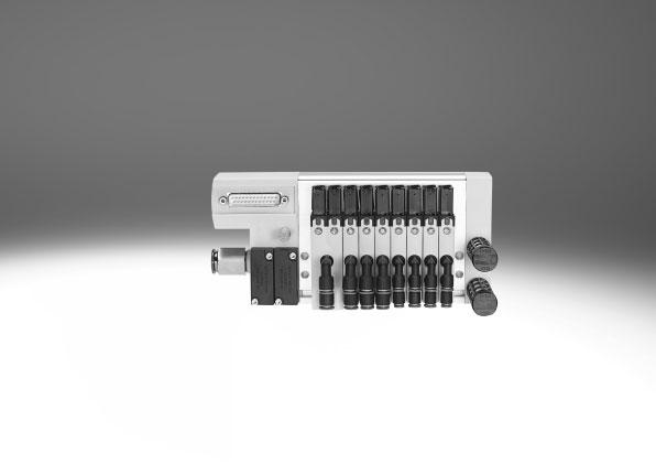
7 -V- New Peripherals overview Overview Valve terminal VTUB-12 with multi-pin plug connection, Sub-D Up to 20 valve positions/solenoid coils, 25-pin Sub-D multi-pin plug connection, code: M From 21 valve positions/solenoid coils, 44-pin Sub-D multi-pin plug connection, code: M Valve terminals with electrical multipin plug connection are available with 2 to max. 35 valve positions. Each valve position can either be equipped with a valve, a pressure zone supply module or a blanking plate. Double solenoid valves occupy two valve positions. A maximum of 35 solenoid coils can be actuated via the electrical multipin plug connection. Up to 18 pressure zones are possible aj 1 aa ab 3 ac aa ab Accessories Brief description 1 Connecting cable NEBV For multi-pin plug connection, with Sub-D plug 37 2 Push-in fitting QS For connecting compressed air tubing with standard O.D Selector plate VABF Pilot control with external pilot air (optional) 36 4 Pneumatic distributor VABF For connecting additional distributors to the air supply (port 1) 35 5 Blanking plate VABB For vacant position (pneumatic distributor) 35 6 Silencer U For venting hole 38 7 Solenoid valve VUVB Pressure zone supply module VABF For supplying pressure zones or for additional air supply 35 9 Blanking plate VABB For vacant position (solenoid valve) 35 aj Silencer U For fitting in exhaust ports 38 aa Fittings QS For connecting compressed air tubing with standard O.D. 38 ab Blanking plug B For sealing the air supply port 36 ac Manifold rail VABM With multi-pin plug connection, for connecting max. 35 valves 34 Separator VABD For duct separation in duct 1, for creating pressure zones 36 Page/Internet 2014/08 Subject to change Internet: 7
8 -V- New Peripherals overview Overview Valve terminal VTUB-12 with I-Port interface/io-link Up to 35 valve positions/solenoid coils I-Port interface connection type, code: PT IO-Link connection type, code: LK The electrical supply/transmission of communication data takes place via an M12 plug. The valve terminal can be equipped with 3 35 valves. Up to 18 pressure zones are possible. Each valve position can either be equipped with a valve, a pressure zone supply module or a blanking plate. Double solenoid valves occupy two valve positions. The following protocols are supported when using the associated fieldbus node CTEU: DeviceNet CANopen PROFIBUS DP EtherCAT CC-Link aj aa ab ac 3 6 ad 1 2 ae ac ad Accessories Brief description 1 Bus node CTEU 39 2 Plug SEA-M12 Straight, for T-adapter FB-TA 39 3 T-adapter FB-TA For IO-Link and load voltage 39 4 Pneumatic distributor VABF For connecting additional distributors to the air supply (port 1) 35 5 Push-in fitting QS 34 6 Selector plate VABF Pilot control with external pilot air (optional) 36 7 Blanking plate VABB For vacant position (pneumatic distributor) 35 8 Silencer U For venting hole 38 9 Solenoid valve VUVB aj Pressure zone supply module VABF For supplying pressure zones or for additional air supply 35 aa Blanking plate VABB For vacant position (solenoid valve) 35 ab Silencer U For fitting in exhaust ports 38 ac Fittings QS For connecting compressed air tubing with standard O.D. 38 ad Blanking plug B For sealing the air supply port 36 ae Manifold rail VABM With I-Port interface, for connecting max. 35 valves 34 Separator VABD For duct separation in duct 1, for creating pressure zones 36 Page/Internet 8 Internet: Subject to change 2014/08
9 Peripherals overview Sub-base for semi in-line valve Single design for single solenoid valves Double design for double solenoid valves Electrical connection via plug socket with cable KMYZ and adapter (M8x1) with corresponding connecting cable aj 9 8 aa Accessories Brief description 1 Single solenoid valve VUVB Double solenoid valve VUVB Push-in fitting QS For port 2, 4: cartridge with push-in connector 38 4 Sub-base VABS Double design for individual double solenoid valve 35 5 Sub-base VABS Single design for individual single solenoid valve 35 6 Silencer AMTC For port 3, 5 (optional) 38 7 Push-in fitting QS For port 1: cartridge with push-in connector 38 8 Push-in fitting QS For port 12, 14: cartridge with push-in connector (optional) 38 9 Adapter VAVE M8x1 (optional), LED 39 aj Plug socket with cable KMYZ Connecting cable (optional) 37 aa Inscription label holder IBS-6x10 36 Page/Internet 2014/08 Subject to change Internet: 9
10 Key features Pneumatic components Wide range of pneumatic components The use of the same basic valves for the 3/2-way and 5/2-way valve function permits fast and flexible conversion and multiple use of parts. Flexible construction thanks to assembled and tested units or individual components as modules for individual configurations. Flow rates from l/min depending on the valve used and appropriate QS connections. Changing fittings on port 2/4 The cartridges (port 2/4) can be changed quickly and easily by removing the spring clip. The ports can be sealed by inserting a blanking plug ( 36). Connection to the valve Rear Right T (on top, inline) TA (on top, angled outlet to the front) TB (on top, angled outlet to the front/rear) TC (on top, angled outlet to the rear) TC T TA TB Connection sizes: Push-in connector 4 mm (code P4) Push-in connector 6 mm (code P6) Front Left Pilot air supply Internal External The port for the pneumatic main supply is located on the left-hand sub-base (multi-pin plug connection/ I-Port interface). The internal pilot air (duct 12/14) is branched from duct 1 in the left-hand sub-base. The air is branched using a pneumatic distributor or a blanking plate on the left-hand pneumatic distributor port. The multi-pin plug connection provides two pneumatic distributor ports and the I-Port interface provides one. External pilot air is supplied via the selector plate on the left-hand pneumatic distributor port. It enables the pilot air and main supply to the valve terminal to be separated. The multi-pin plug connection provides one pneumatic distributor port and the I-Port interface does not provide any. 10 Internet: Subject to change 2014/08
11 -V- New Key features Pneumatic components Creating pressure zones Up to 18 pressure zones can be created using the separator VABD C8 if different working pressures are required. The separators are inserted at the required location in duct 1 in the manifold rail and screwed into place. The following rules apply: Two pressure zones can be realised without an additional pressure zone supply module (VABF-C8 ) if there is a compressed air supply at both ends. Only one separator in duct 1 is required for this. A pressure zone supply module (VABF-C8 ) is additionally required after the third pressure zone; this module occupies one valve position. There must be at least 2 valve positions between 2 separators. -H- Note Pressure zones can be freely configured with the VTUB-12. Duct separation does not result in any valve positions being lost, however valve positions will be lost if an additional supply is required. If a valve terminal with duct separation is ordered via the configurator, the duct separation comes already labelled. Older manifold rails predating approx. mid-2013 cannot be retrofitted for the purpose of creating pressure zones. Further information on assembly Assembly instructions for VABD C8 P1 D2 Duct separation Description Duct separation and creation of pressure zones Remove the end plate. Insert an Allen key (size 4) from above at the required position in duct 1 in the manifold rail as a stop. Using another Allen key, push separator VABD C8 into duct 1 as far as it will go until it is in the appropriate position and then turn the Allen key to secure in place. Fit the end plate. Affix the enclosed symbol labels to the duct separation. Design Valve replacement The valves are attached to the aluminium manifold rail using one screw, which means that they can be easily Expansion replaced. Use of high-quality plastics guarantees minimum weight and maximum performance. Blanking plates can be replaced by valves at a later date. The dimensions, mounting points and the pneumatic installation already carried out do not change. Valve function Code Circuit symbol Width Description 12 mm 24 mm M 5/2-way valve, single solenoid Mechanical spring return Non-reversible Not suitable for vacuum J 5/2-way valve, double solenoid Non-reversible Not suitable for vacuum N K 3/2-way valve, single solenoid Normally open Mechanical spring return Non-reversible Not suitable for vacuum 3/2-way valve, single solenoid Normally closed Mechanical spring return Non-reversible Not suitable for vacuum 2014/08 Subject to change Internet: 11
12 Key features Display and operation Display and operation Manual override (non-detenting, non-detenting/detenting) 2 Screw for valve assembly The manual override enables the valve to be switched without electronic control or power supply. Manual override Manual override with automatic reset (non-detenting) Press in the stem of the manual override with a pointed object or screwdriver. > The valve is switched. Remove the pointed object or screwdriver. Spring force pushes the stem of the manual override back. > Valve returns to normal position. Manual override with lock (non-detenting/detenting) Press in the stem of the manual override with a pointed object or screwdriver until the valve switches and then turn the stem clockwise by 90 until the stop is reached. > The valve remains switched. Turn the stem anti-clockwise by 90 until the stop is reached and then remove the pointed object or screwdriver. Spring force pushes the stem of the manual override back. > Valve returns to normal position. -H- Note A manually operated valve (manual override) cannot be reset electrically. Conversely, a solenoid actuated valve cannot be reset using the mechanical manual override. 12 Internet: Subject to change 2014/08
13 -V- New Key features Assembly Valve terminal assembly Sturdy valve terminal assembly thanks to: Through-holes for wall mounting H-rail mounting Wall mounting Sturdy terminal assembly thanks to four through-holes for wall mounting (M5 screws). H-rail mounting A B The H-rail mounting VAME-T-M5 consists of two mounting clips. These are attached to the manifold rail on the left and right (M5 screws). The lower through-holes on the manifold rail are used for this. The valve terminal VTUB-12 prepared in this way is lowered onto the H-rail from above (arrow A) and clipped into the H-rail at the bottom (arrow B). -H- Note Note the max. tightening torque of 2 Nm (± 25%) for the screws for mounting the H-rail. Only horizontal H-rail mounting is permissible. Mounting only possible on H-rail TH to EN Vibration/shock loads are not permissible with H-rail mounting. 2014/08 Subject to change Internet: 13
14 -V- New Key features Electrical components Multi-pin plug connection Control signals from the controller to the valve terminal are transmitted via a pre-assembled multi-core cable, which substantially reduces installation time. This valve terminal can be equipped with 2 35 valves. Versions Sub-D connection I-Port interface/io-link IO-Link IO-Link is an interface that supplies data for communication in addition to the power supply. An IO-Link system consists of an IO-Link master and IO-Link devices. The IO-Link master offers the interface to the higher-order controller (PLC) and controls communication with the connected IO-Link devices. One device with IO-Link (e.g. an IO-Link valve terminal from Festo) can be connected to each port on an IO-Link master. I-Port The Festo-specific I-Port interface based on IO-Link offers the following connection options: Directly at the fieldbus, by mounting a fieldbus node CTEU Connection to a higher-order I-Port master from Festo Overview PLC Fieldbus Fieldbus node CTEU (IO-Link master) IO-Link Valve terminal VTUB-12, I-Port interface/io-link 14 Internet: Subject to change 2014/08
15 Key features Electrical components Protective circuit Manifold rail multi-pin plug connection with LED signal status display, 2-20-fold -H- Note The electrical protective circuit only relates to the optional LED variant with the multi-pin plug connection. Manifold rail multi-pin plug connection with LED signal status display, fold Electrical multi-pin plug connection The following multi-pin plug connections are available for the valve terminal VTUB-12: Sub-D multi-pin plug connection (25-pin) Sub-D multi-pin plug connection (44-pin) Pins 1 44 are used for addresses 0 43 in order. If fewer than 44 addresses are used for the valve terminal, the remaining pins are left free. Pins or are reserved for the neutral conductor or 24 V respectively. The valves are switched by means of positive or negative logic (positive switching or negative switching). Mixed operation is not permitted. Each pin on the multi-pin plug can actuate exactly one solenoid coil. If the maximum configurable number of valve positions is 35, then 35 valves can be addressed with one solenoid coil (single solenoid). -H- Note A double solenoid valve occupies two valve positions. With 17 or more valve positions, the number of available valve positions for double solenoid valves decreases. 2014/08 Subject to change Internet: 15
16 Key features Electrical components Pin allocation Sub-D plug, 25-pin -H- Note The drawing shows the view onto the pins of the Sub-D plug. Pin Address/coil 15-wire, NEBV-S1 25-K- -LE15 25-wire, NEBV-S1 25-K- -LE25 Wire colour 1) of connecting cable 1 0 WH WH 2 1 BN BN 3 2 GN GN 4 3 YE YE 5 4 GY GY 6 5 PK PK 7 6 BU BU 8 7 RD RD 9 8 BK BK 10 9 VT VT GY PK GY PK RD BU RD BU GN WH BN GN YE WH BN YE GY WH BN GY WH PK BN PK 21 BU WH 22 0 V/24 V BN BU 23 0 V/24 V GN WH RD WH 24 0 V/24 V BN GN BN RD 25 0 V/24 V YE WH BK WH 1) To IEC Internet: Subject to change 2014/08
17 -V- New Key features Electrical components Pin allocation Sub-D plug, 44-pin NEBV-S1 44-K- -LE39 Pin Address Wire colour 1) Connecting cable Pin Address Wire colour 1) Connecting cable -H- Note The drawing shows the view onto the pins of the Sub-D plug. 1 0 WH WH RD 2 1 BN BN RD 3 2 GN WH BK 4 3 YE BN BK 5 4 GY GY GN 6 5 PK YE GY 7 6 BU PK GN 8 7 RD YE PK 9 8 BK GN BU 10 9 VT YE BU GY PK GN RD RD BU YE RD WH GN GN BK BN GN WH YE YE BN WH GY GY BN WH PK 41 0 V YE BK PK BN 42 0 V GY BU WH BU 43 0 V PK BU BN BU 44 0 V GY RD 1) To IEC 757 Pin allocation Sub-D plug, 44-pin NEBV-S1 44-K- -LE44 Pin Address Wire colour 1) Connecting cable Pin Address Wire colour 1) Connecting cable -H- Note The drawing shows the view onto the pins of the Sub-D plug. 1 0 WH WH RD 2 1 BN BN RD 3 2 GN WH BK 4 3 YE BN BK 5 4 GY GY GN 6 5 PK YE GY 7 6 BU PK GN 8 7 RD YE PK 9 8 BK GN BU 10 9 VT YE BU GY PK GN RD RD BU YE RD WH GN GN BK BN GN YE BK WH YE GY BU YE BN PK BU WH GY GY RD GY BN PK RD WH PK 41 0 V GY BK PK BN 42 0 V PK BK WH BU 43 0 V BU BK BN BU 44 0 V RD BK 1) To IEC /08 Subject to change Internet: 17
18 Key features Electrical components Pin allocation Adapter M8x1 with LED Round plug, M8, 3-pin Round plug, M8, 4-pin Pin VAVE-C8-1R8 1 Not used 3 0 V 4 24 V VAVE-C8-1R1 1 Not used 2 Not used 3 0 V 4 24 V 1) To DIN EN Protective circuit Manifold rail with I-Port interface I-Port interface/io-link The valve terminal VTUB-12 can be connected as follows via the I-Port connection: Directly to the fieldbus by mounting the CTEU bus node on the valve terminal To an IO-Link master (in IO-Link mode) via a cable Up to 35 solenoid coils can be actuated. A valve position always occupies one address. The following assignment applies in this case: Less significant valve position (address) for coil 14 More significant valve position (address) for coil 12 Addresses are allocated in ascending order without gaps, from left to right. The address allocation is independent of whether blanking plates or valves are used. -H- Note More information on CTEU cteu Additionally required IODD for IO-Link mode Pin allocation of the I-Port interface/io-link 1) Pin Allocation 1 24 V electronics (logic voltage) 2 24 V valves (load voltage) 3 0 V electronics (logic) 4 COM I-Port communication signal 5 0 V valves (load) 1) 5-pin plug, M12, A-coded 18 Internet: Subject to change 2014/08
19 Key features Applications Equipment Operate system equipment with unlubricated compressed air if possible. Festo valves and cylinders are designed so that, if used as intended, they will not require additional lubrication and will still achieve a long service life. The compressed air prepared with the compressor must correspond in quality to unlubricated compressed air. If possible, do not operate all of your system equipment with lubricated compressed air. The lubricators should, where possible, always be installed directly upstream of the actuator used. Incorrect additional oil and too high an oil content in the compressed air reduce the service life of the valve terminal. Use Festo special oil OFSW-32 or the alternatives listed in the Festo catalogue (as specified in DIN HLP32; basic oil viscosity 32 CST at 40 C). Bio-oils When using bio-oils (oils which are based on synthetic or native ester, e.g. rapeseed oil methyl ester), the maximum residual oil content of 0.1 mg/m 3 must not be exceeded (see ISO Class 2). Mineral oils When using mineral oils (e.g. HLP oils to DIN 51524, parts 1 to 3) or similar oils based on poly-alpha-olefins (PAO), the maximum residual oil content of 5 mg/m 3 must not be exceeded (see ISO Class 4). A higher residual oil content irrespective of the compressor oil cannot be permitted, as the basic lubricant would be flushed out over time. 2014/08 Subject to change Internet: 19
20 Technical data Valve terminal VTUB-12 with multi-pin plug connection -P- Voltage 24 V DC -L- Pressure bar -Q- Temperature range C General technical data Valve function 3/2C 3/2U 5/2-way, single solenoid 5/2-way, double solenoid Design Poppet valve with spring return Poppet valve with self-holding function Valve function Closed Open Single solenoid Double solenoid Sealing principle Soft Actuation type Electric Reset method Mechanical spring Type of control Piloted Pilot air supply Internal External Direction of flow Non-reversible Exhaust function No flow control Manual override Non-detenting, non-detenting/detenting Type of mounting Via through-hole Width [mm] Nominal size [mm] 4 Max. number of valve positions Max. number of pressure zones 18 Standard nominal flow rate qnn [l/min] 400 Pneumatic connection 1, 3, 5 G¼ 2, 4 QS-4 or QS-6 12, 14 Gx Operating and environmental conditions Valve function 3/2C 3/2U 5/2-way, single solenoid 5/2-way, double solenoid Operating medium Compressed air to ISO :2010 [7:4:4] Note on operating/pilot medium Lubricated operation possible (in which case lubricated operation will always be required) Operating pressure Internal pilot air [bar] External pilot air [bar] 0 +8 Pilot pressure [bar] Ambient temperature [ C] Temperature of medium [ C] CE marking To EU EMC Directive * 20 Internet: Subject to change 2014/08
21 Technical data Valve terminal VTUB-12 with multi-pin plug connection Product weight Approx. weight [g] Valves 5/2-way single solenoid (code M), ducted solenoid exhaust 5/2way double solenoid (code J), ducted solenoid exhaust 5/2-way single solenoid (code M), unducted solenoid exhaust 5/2-way double solenoid (code J), unducted solenoid exhaust 3/2-way closed (code K), ducted/unducted solenoid exhaust 3/2-way open (code N), unducted solenoid exhaust 3/2-way open (code N), ducted solenoid exhaust Manifold rail Multi-pin plug with Sub-D plug, 25-pin 2 valve positions valve positions valve positions valve positions valve positions valve positions valve positions valve positions 1, valve positions 1,195 Multi-pin plug with Sub-D plug, 44-pin 20 valve positions 1, valve positions 1, valve positions 1, valve positions 1, valve positions 2,060 Blanking plate for vacant position 13.8 Pressure zone supply module for pressure zones or additional supply 13.8 Separator for duct separation 9.8 Pneumatic distributor Q4, Q6, Q4-Q6 65.6, 59, 62.3 Blanking plate for pneumatic distributor 8.4 Selector plate 38.8 Sub-base for individual valve, single width 15 Sub-base for individual valve, double width 30 Electrical data Nominal operating voltage [V DC] 24, reverse polarity protected Permissible voltage fluctuations ±10% Electrical power consumption per solenoid coil [W] 1 Protection class to EN IP65 Duty cycle [%] 100 Materials Manifold rail Solenoid valve housing Solenoid valve seals Solenoid valve piston spool Blanking plate housing, additional supply housing Separator for duct separation Pneumatic distributor, pneumatic distributor blanking plate Selector plate Sub-base for individual valve Note on materials Wrought aluminium alloy PA reinforced NBR, TPE-U Wrought aluminium alloy PA reinforced Beryllium bronze, brass PA reinforced Wrought aluminium alloy PA reinforced RoHS-compliant 2014/08 Subject to change Internet: 21

22 Technical data Valve terminal VTUB-12 with I-Port interface, IO-Link -P- Voltage 24 V DC -L- Pressure bar -Q- Temperature range C General technical data Valve function 3/2C 3/2U 5/2-way, single solenoid 5/2-way, double solenoid Design Poppet valve with spring return Poppet valve with self-holding function Valve function Closed Open Single solenoid Double solenoid Sealing principle Soft Actuation type Electric Reset method Mechanical spring Type of control Piloted Pilot air supply Internal External Direction of flow Non-reversible Exhaust function No flow control Manual override Non-detenting, non-detenting/detenting Type of mounting Via through-hole Width [mm] Nominal size [mm] 4 Max. number of valve positions Max. number of pressure zones 18 Standard nominal flow rate qnn [l/min] 400 Pneumatic connection 1, 3, 5 G¼ 2, 4 QS-4 or QS-6 12, 14 Gx Operating and environmental conditions Valve function 3/2C 3/2U 5/2-way, single solenoid 5/2-way, double solenoid Operating medium Compressed air to ISO :2010 [7:4:4] Note on operating/pilot medium Lubricated operation possible (in which case lubricated operation will always be required) Operating pressure Internal pilot air [bar] External pilot air [bar] 0 +8 Pilot pressure [bar] Ambient temperature [ C] Temperature of medium [ C] CE marking To EU EMC Directive * -H- Note The CE marking for the valve terminal with I-Port interface applies up to a maximum connecting cable length of 30 m. 22 Internet: Subject to change 2014/08
23 Technical data Valve terminal VTUB-12 with I-Port interface, IO-Link Product weight Approx. weight [g] Valves 5/2-way single solenoid (code M), ducted solenoid exhaust 5/2way double solenoid (code J), ducted solenoid exhaust 5/2-way single solenoid (code M), unducted solenoid exhaust 5/2-way double solenoid (code J), unducted solenoid exhaust 3/2-way closed (code K), ducted/unducted solenoid exhaust 3/2-way open (code N), unducted solenoid exhaust 3/2-way open (code N), ducted solenoid exhaust I-Port interface with M12 plug 4 valve positions valve positions valve positions valve positions valve positions valve positions 1, valve positions 1, valve positions 1, valve positions 1, valve positions 1, valve positions 1, valve positions 1, valve positions 2,138 Blanking plate for vacant position 13.8 Pressure zone supply module for pressure zones or additional supply 13.8 Separator for duct separation 9.8 Pneumatic distributor Q4, Q6, Q4-Q6 65.6, 59, 62.3 Blanking plate for pneumatic distributor 8.4 Selector plate 38.8 Sub-base for individual valve, single width 15 Sub-base for individual valve, double width 30 Electrical data Nominal operating voltage [V DC] 24, reverse polarity protected Permissible voltage fluctuations ±10% Electrical power consumption per solenoid coil [W] 1 Protection class to EN IP65 Duty cycle [%] 100 Intrinsic current consumption, logic supply [ma] 30 Intrinsic current consumption, valve supply [ma] 30 Max. cable length [m] 20 Min. cable cross section [mm 2 ] 1 Baud rate COM3 [kbps] COM2 [kbps] 38.4 Materials Manifold rail Solenoid valve housing Solenoid valve seals Solenoid valve piston spool Blanking plate housing, additional supply housing Separator for duct separation Pneumatic distributor, pneumatic distributor blanking plate Selector plate Sub-base for individual valve Note on materials Wrought aluminium alloy PA reinforced NBR, TPE-U Wrought aluminium alloy PA reinforced Beryllium bronze, brass PA reinforced Wrought aluminium alloy PA reinforced RoHS-compliant 2014/08 Subject to change Internet: 23
24 Technical data Valve switching times [ms] Valve function 3/2-way 5/2-way, single solenoid 5/2-way, double solenoid On 6 6 Off Changeover 10 Pilot pressure as a function of operating pressure (operating pressure with external pilot air), pilot pressure 5/2 and 3/2U Pilot pressure as a function of operating pressure (operating pressure with external pilot air), pilot pressure 3/2C Flow rate q per valve with multiple (n) valves switched simultaneously (tolerance _ 20%) Flow rate per valve Loss per valve [%] 24 Internet: Subject to change 2014/08
25 Technical data Materials Sectional view Valves 1 2 Double solenoid Single solenoid 1 Housing PA reinforced 2 Piston spool Wrought aluminium alloy Seals NBR, PUR Manifold rail with multi-pin plug Wrought aluminium alloy Pressure zone supply module PA reinforced Blanking plate for vacant position PA reinforced Selector plate Wrought aluminium alloy Dimensions Pressure zone supply module Download CAD data 2 Mounting screw M2,5 3 Push-in connectors QSP 10 - Type B1 H1 H2 L1 L2 L3 L5 VABF-C8-12-P3A5-QX /08 Subject to change Internet: 25
26 Technical data Dimensions 3/2-way valve, single solenoid, normally open Download CAD data 1 Manual override non-detenting or non-detenting/detenting 2 M2.5 mounting screw Type B1 B2 B3 B4 B5 H1 H2 H3 H4 L1 L2 L3 L4 L5 L6 VUVB-ST12-M32U- -QX-1T VUVB-ST12-M32U- -QX-D-1T Dimensions 3/2-way valve, single solenoid, normally closed Download CAD data 1 Manual override non-detenting or non-detenting/detenting 2 M2.5 mounting screw Type B1 B2 B3 B4 B5 H1 H2 H3 H4 L1 L2 L3 L5 L6 VUVB-ST12-M32C- -QX-1T VUVB-ST12-M32C- -QX-D-1T Internet: Subject to change 2014/08
27 Technical data Dimensions 5/2-way valve, single solenoid Download CAD data 1 Manual override 2 Mounting screw Type B1 B2 B3 B4 B5 B6 B7 H1 H2 H3 H4 L1 L2 L3 L4 L5 L6 L7 VUVB-ST12-M52-MZH-QX-1T VUVB-ST12-M52-MZH-QX-D-1T Dimensions 5/2-way valve, double solenoid Download CAD data 1 Manual override 2 Mounting screw Type B1 B2 B3 B4 B5 B6 B7 H1 H2 H3 H4 L1 L2 L3 L4 L5 L6 L7 VUVB-ST12-B52-ZH-QX-1T VUVB-ST12-B52-ZH-QX-D-1T /08 Subject to change Internet: 27
28 Technical data Dimensions Manifold rail with multi-pin plug Download CAD data LED signal status display (optional) n Number of valve positions (2 35) Type B1 B2 B3 B4 B5 B6 B7 D1 D2 H1 H2 H3 H4 VABM-C8-12E G¼ Type L1 L2 L3 L4 L5 L6 L7 L8 L9 VABM-C8-12E (n x 12) (n x 12) + 20 (n x 12) Internet: Subject to change 2014/08
29 Technical data Dimensions Manifold rail with I-Port interface Download CAD data 1 LED signal status display 2 M4 earthing screw n Number of valve positions (3 35) Type B1 B2 B3 B4 B5 B6 B7 D1 D2-N- H1 H2 H4 H5 VTUB G¼ Type L1 L2 L3 L5 L6 L7 L8 L9 VTUB-12 (nx12)+100 (nx12)+20 (nx12) /08 Subject to change Internet: 29
30 Technical data Dimensions Valve terminal Download CAD data With electrical multi-pin plug 1 5/2-way valve 2 Blanking plate for vacant position 3 Silencer, threaded connection M5 4 Sub-D plug, 25-pin or 44-pin with 21 or more solenoid coils 5 Silencer, threaded connection G¼ 6 Hole for wall mounting, 5.5 mm 7 Fittings for air supply port n Number of valve positions (2 35) Type L1 L2 L3 L4 L5 L6 L7 L8 L9 L10 L11 L12 L13 L14 L15 L16 L17 VTUB-12 (n x 12) _1.5 (n x 12) + 20 (n x 12) _ _ Type B1 B2 B3 B4 B5 B6 B7 B8 B9 B10 D1 H1 H2 H12 H13 VTUB _ _ G¼ 88.2 _1 82 _ Internet: Subject to change 2014/08
31 Technical data Dimensions Valve terminal With I-Port interface, fieldbus node CTEU Download CAD data 1 M4 earthing screw 2 M12 plug, 5-pin 3 Silencer, threaded connection M5 4 Holes for mounting Silencer, threaded connection G¼ 6 Fittings for air supply port 7 External pilot air port 12/14, Gx 8 Bus node CTEU n Number of valve positions (3 35) Type B2 B3 B4 B5 B7 B8 B9 B10 D1 H1 H2 H11 H12 H13 VTUB G¼ Type L1 L2 L3 L4 L5 L6 L9 L11 L12 L13 L14 L15 L16 L17 VTUB-12 (nx12)+100 (nx12)+20 (nx12) /08 Subject to change Internet: 31
32 Technical data Dimensions Sub-base for semi in-line valve (single solenoid) Download CAD data 1 Connecting cable (optional) 2 Adapter M8x1 (optional) 3 Port 2, 4: cartridge with push-in connector 4 Plug socket with cable KMYZ (optional) 5 Port 12, 14: cartridge with push-in connector (optional) 6 Port 1: cartridge with push-in connector 7 Port 3, 5: silencer AMTC-P-PC10 (optional) 8 Holes for M4 mounting 9 Exhaust port 82/84 aj Mounting space for spring clips for solenoid valve aa Mounting space for spring clips for sub-base ab Slot for inscription label IBS6x10 (not included in the scope of delivery) Type B1 B2 H1 H2 H3 H4 H5 H6 L1 L2 L3 L4 L5 L6 L7 L8 L9 L10 L11 L12 W1 VABS-C8-12XB-QX-B VABS-C8-12XB-QX 32 Internet: Subject to change 2014/08
33 Technical data Dimensions Sub-base for semi in-line valve (double solenoid) Download CAD data 1 Connecting cable (optional) 2 Adapter M8x1 (optional) 3 Port 2, 4: cartridge with push-in connector 4 Plug socket with cable KMYZ (optional) 5 Port 12, 14: cartridge with push-in connector (optional) 6 Port 1: cartridge with push-in connector 7 Port 3, 5: silencer AMTC-P-PC10 (optional) 8 Holes for M4 mounting 9 Exhaust port 82/84 aj Mounting space for spring clips for solenoid valve aa Mounting space for spring clips for sub-base ab Slot for inscription label IBS6x10 (not included in the scope of delivery) Type B1 B2 H1 H2 H3 H4 H5 H6 L1 L2 L3 L4 L5 L6 L7 L8 L9 L10 L11 L12 W1 VABS-C8-12XB-QX-B VABS-C8-12XB-QX 2014/08 Subject to change Internet: 33
34 Accessories Ordering data Code Valve function Solenoid exhaust air Part No. Type Solenoid valves M Y K N 5/2-way valve, single solenoid, manual override non-detenting 5/2-way valve, single solenoid, manual override non-detenting/detenting 5/2-way valve, double solenoid, manual override non-detenting 5/2-way valve, double solenoid, manual override non-detenting/detenting 3/2-way valve, single solenoid, closed, manual override non-detenting 3/2-way valve, single solenoid, closed, manual override non-detenting/detenting 3/2-way valve, single solenoid, open, manual override non-detenting 3/2-way valve, single solenoid, open, manual override non-detenting/detenting Unducted VUVB-ST12-M52-MZH-QX-1T1 Ducted VUVB-ST12-M52-MZH-QX-D-1T1 Unducted VUVB-ST12-M52-MZD-QX-1T1 Ducted VUVB-ST12-M52-MZD-QX-D-1T1 Unducted VUVB-ST12-B52-ZH-QX-1T1 Ducted VUVB-ST12-B52-ZH-QX-D-1T1 Unducted VUVB-ST12-B52-ZD-QX-1T1 Ducted VUVB-ST12-B52-ZD-QX-D-1T1 Unducted VUVB-ST12-M32C-MZH-QX-1T1 Ducted VUVB-ST12-M32C-MZH-QX-D-1T1 Unducted VUVB-ST12-M32C-MZD-QX-1T1 Ducted VUVB-ST12-M32C-MZD-QX-D-1T1 Unducted VUVB-ST12-M32U-MZH-QX-1T1 Ducted VUVB-ST12-M32U-MZH-QX-D-1T1 Unducted VUVB-ST12-M32U-MZD-QX-1T1 Ducted VUVB-ST12-M32U-MZD-QX-D-1T1 Manifold rail Multi-pin plug with Sub-D plug, 25-pin VABM-C8-12E-G14-2-M VABM-C8-12E-G14-4-M VABM-C8-12E-G14-6-M VABM-C8-12E-G14-8-M VABM-C8-12E-G14-10-M VABM-C8-12E-G14-12-M VABM-C8-12E-G14-14-M VABM-C8-12E-G14-16-M VABM-C8-12E-G14-18-M VABM-C8-12E-G14-20-M1 Multi-pin plug with Sub-D plug, 44-pin VABM-C8-12E-G14-24-M VABM-C8-12E-G14-28-M VABM-C8-12E-G14-32-M VABM-C8-12E-G14-35-M1 L Multi-pin plug with Sub-D plug, 25-pin, LED signal status display Multi-pin plug with Sub-D plug, 44-pin, LED signal status display VABM-C8-12E-G14-2-M1-L VABM-C8-12E-G14-4-M1-L VABM-C8-12E-G14-6-M1-L VABM-C8-12E-G14-8-M1-L VABM-C8-12E-G14-10-M1-L VABM-C8-12E-G14-12-M1-L VABM-C8-12E-G14-14-M1-L VABM-C8-12E-G14-16-M1-L VABM-C8-12E-G14-18-M1-L VABM-C8-12E-G14-20-M1-L VABM-C8-12E-G14-24-M1-L VABM-C8-12E-G14-28-M1-L VABM-C8-12E-G14-32-M1-L VABM-C8-12E-G14-35-M1-L 34 Internet: Subject to change 2014/08
35 -V- New Accessories Ordering data Manifold rail Code Description Valve positions Part No. Type PT/LK Manifold rail with I-Port interface VABM-C8-12E-G14-4-PT-L VABM-C8-12E-G14-6-PT-L VABM-C8-12E-G14-8-PT-L VABM-C8-12E-G14-10-PT-L VABM-C8-12E-G14-12-PT-L VABM-C8-12E-G14-14-PT-L VABM-C8-12E-G14-16-PT-L VABM-C8-12E-G14-18-PT-L VABM-C8-12E-G14-20-PT-L VABM-C8-12E-G14-24-PT-L VABM-C8-12E-G14-28-PT-L VABM-C8-12E-G14-32-PT-L VABM-C8-12E-G14-35-PT-L Sub-base for individual valve Internal pilot air supply 1 (M52/M32) VABS-C8-12XB-QX-B External pilot air supply 1 (M52/M32) VABS-C8-12XB-QX Internal pilot air supply 1 (B52) VABS-C8-12XB-QX-DB External pilot air supply 1 (B52) VABS-C8-12XB-QX-D Pressure zone supply module S For additional air supply or for supplying pressure zones VABF-C8-12-P3A5-QX Ordering data Blanking plate Code Description Part No. Type L Blanking plate for vacant valve position VABB-C8-12-ET Blanking plate for pneumatic distributor position VABB-C8-12-A Pneumatic distributor AL Push-in connector 4 mm VABF-C8-12-V1P4-Q4 BL Push-in connector 6 mm VABF-C8-12-V1P4-Q6 CL Push-in connector 4 and 6 mm VABF-C8-12-V1P4-Q4-Q6 2014/08 Subject to change Internet: 35
36 -V- New Accessories Ordering data Code Description Packaging unit Part No. Type Selector plate SL Pneumatic connection G1/8 1 piece VABF-C8-12-P6-G18-Z H-rail mounting H For mounting the valve terminal VTUB-12 on a standard H-rail TH to EN (Use the following screws for mounting: M5x40 to DIN 912, 2 pieces) 2 pieces VAME-T-M5 Separator SP For creating pressure zones (duct separation in duct 1) 1 piece VABD-C8-P1 Blanking plug Connection 10 mm 1 piece QSPC10 For thread G¼ 10 pieces 3569 B-¼ Inscription labels Inscription labels 6x10mm, 64 pieces, in frames 1 piece IBS-6x10 Ordering data Code Description Cable length Part No. Type [m] Connecting cables for multi-pin plug M1 Sub-D, 15-pin, straight socket, up to 12 coils, IP NEBV-S1G25-K-2.5-N-LE15 M2 Open end, 15 wires NEBV-S1G25-K-5-N-LE15 M NEBV-S1G25-K-10-N-LE15 M1 Sub-D, 25-pin, straight socket, up to 20 coils, IP NEBV-S1G25-K-2.5-N-LE25 M2 Open end, 25 wires NEBV-S1G25-K-5-N-LE25 M NEBV-S1G25-K-10-N-LE25 M1 Sub-D, 44-pin, straight socket, up to 35 coils, IP NEBV-S1G44-K-2.5-N-LE39 M2 Open end, 40 wires NEBV-S1G44-K-5-N-LE39 M NEBV-S1G44-K-10-N-LE39 M1L Sub-D, 25-pin, straight socket, up to 20 coils, IP NEBV S1G25 K 2.5 N LE25 S6 M2L Open end, 25 wires NEBV S1G25 K 5 N LE25 S6 M3L NEBV S1G25 K 10 N LE25 S6 M1L Sub-D, 44-pin, straight socket, up to 35 coils, IP NEBV-S1G44-K-2.5-N-LE44-S6 M2L Open end, 44 wires NEBV-S1G44-K-5-N-LE44-S6 M3L NEBV-S1G44-K-10-N-LE44-S6 MA1 Sub-D, 25-pin, angled socket, up to 20 coils, IP NEBV S1WA25 K 2.5 N LE25 S9 MA2 Open end, 25 wires NEBV S1WA25 K 5 N LE25 S9 MA NEBV S1WA25 K 10 N LE25 S9 MA1 Sub-D, 44-pin, angled socket, up to 35 coils, IP NEBV S1WA44 K 2.5 N LE44 S9 MA2 Open end, 44 wires NEBV S1WA44 K 5 N LE44 S9 MA NEBV S1WA44 K 10 N LE44 S9 36 Internet: Subject to change 2014/08
37 Accessories Ordering data Description Cable length Part No. Type [m] Plug socket with cable for individual valve Angled socket, square design, 2-pin, cable open at one end, 2-wire, with LED, IP65 Angled socket, square design, 2-pin, straight plug, M8x1, 3-pin, with LED, IP65 Angled socket, square design, 2-pin, cable with open end, 2-wire, without LED, IP KMYZ ,5-LED-PUR-B KMYZ LED-PUR-B KMYZ LED-PUR-B KMYZ-9-24-M8-0,5-LED-B KMYZ-9-24-M8-2,5-LED-B KMYZ ,5 B KMYZ ,5 B Connecting cables Open cable end, 3-wire Socket M8x1, straight, 3-pin NEBU-M8G3-K-2.5-LE NEBU-M8G3-K-5-LE NEBU-M8G3-K-10-LE SIM-M8-3GD-2,5-PU SIM-M8-3GD-5-PU SIM-M8-3GD-10-PU Socket M8x1, angled, 3-pin NEBU-M8W3-K-2.5-LE NEBU-M8W3-K-5-LE NEBU-M8W3-K-10-LE SIM-M8-3WD-2,5-PU SIM-M8-3WD-5-PU SIM-M8-3WD-10-PU Open cable end, 4-wire Socket M8x1, straight, 4-pin NEBU-M8G4-K-2.5-LE NEBU-M8G4-K-5-LE SIM-M8-4GD-2,5-PU SIM-M8-4GD-5-PU Socket M8x1, angled, 4-pin NEBU-M8W4-K-2.5-LE NEBU-M8W4-K-5-LE SIM-M8-4WD-2,5-PU SIM-M8-4WD-5-PU Straight plug, 3-pin Socket M8x1, straight, 3-pin NEBU-M8G3-K-0.5-M8G NEBU-M8G3-K-1-M8G NEBU-M8G3-K-2.5-M8G NEBU-M8G3-K-5-M8G NEBU-M8G3-K-10-M8G3 Straight plug, 4-pin Socket M8x1, straight, 3-pin NEBU-M8G3-K-2.5-M8G4 Socket M8x1, straight, 4-pin NEBU-M8G4-K-2.5-M8G4 2014/08 Subject to change Internet: 37
38 Accessories Ordering data Description Tubing O.D. Packaging unit Part No. Type Push-in fitting With sealing ring Connection G¼ Technical data Internet: quick star 8 mm 10 pieces QS-G¼-8 10 mm 10 pieces QS-G¼ mm 10 pieces QS-G¼-12 Push-in L-fitting With sealing ring Connection G¼ Technical data Internet: quick star 8 mm 10 pieces QSL-G¼-8 10 mm 10 pieces QSL-G¼ mm 10 pieces QSL-G¼-12 Push-in L-fitting, long With sealing ring Connection G¼ Technical data Internet: quick star 8 mm 10 pieces QSLL-G¼-8 10 mm 10 pieces QSLL-G¼ mm 10 pieces QSLL-G¼-12 Cartridge with push-in connector Straight Connection 10 mm L-shape Connection 10 mm L-shape, long Connection 10 mm 4 mm 10 pieces QSP mm 10 pieces QSP mm 10 pieces QSPLK mm 10 pieces QSPLK mm 10 pieces QSPLLK mm 10 pieces QSPLLK10-6 Silencer For thread M5 1 piece 4645 U-M5 Technical data Internet: u For thread G¼ 1 piece 2316 U-¼ For individual sub-base, QSP10 1 piece AMTC-P-P10 38 Internet: Subject to change 2014/08
39 -V- New Accessories Ordering data Adapter M8x1 Code Description Part No. Type Plug M8x1, 3-pin, with LED VAVE-C8-1R8 Plug M8x1, 4-pin, with LED VAVE-C8-1R1 Ordering data I-Port interface/io-link Code Description Part No. Type Connection technology for IO-Link XM T-adapter M12, 5-pin, for IO-Link and load supply FB-TA-M12-5POL XN Straight plug, M12, 5-pin, for T-adapter FB-TA SEA-M12-5GS-PG7 Ordering data CTEU Bus node Part No. CANopen fieldbus node CTEU CO Type DeviceNet fieldbus node CTEU-DN CC-Link fieldbus node CTEU-CC PROFIBUS fieldbus node CTEU-PB EtherCAT fieldbus node CTEU-EC Bus connection Sub-D plug, straight, for DeviceNet/CANopen FBS-SUB-9-BU-2x5POL-B Sub-D plug, straight, for CC-Link FBS-SUB-9-GS-2x4POL-B Sub-D plug, straight, for PROFIBUS FFBS-SUB-9-GS-DP-B Sub-D plug, angled, for CANopen, 9-pin FBS-SUB-9-WS-CO-K Sub-D plug, angled, for PROFIBUS, 9-pin FBS-SUB-9-WS-PB-K M12x1, 5-pin, A-coded, for DeviceNet/CANopen FBA-2-M12-5POL M12x1, 5-pin, B-coded, for PROFIBUS FBA-2-M12-5POL-RK For 5-pin terminal strip for DeviceNet/CANopen FBA-1-SL-5POL Terminal strip, 5-pin, for DeviceNet/CANopen FBSD-KL-2x5POL 2014/08 Subject to change Internet: 39
40 -V- New Accessories Ordering data CTEU Part No. Type Bus connection Screw terminal for CC-Link FBA-1-KL-5POL Fieldbus socket, M12x1, 5-pin, for DeviceNet/CANopen FBSD-GD-9-5POL Plug, M12x1, 5-pin, for DeviceNet/CANopen FBS-M12-5GS-PG9 Straight socket, M12x1, 5-pin, for assembling a connecting cable compatible with FBA-2-M12-5POL-RK for PROFIBUS NECU-M-B12G5-C2-PB Straight plug, M12x1, 5-pin, for assembling a connecting cable compatible with FBA-2-M12-5POL-RK for PROFIBUS NECU-M-S-B12G5-C2-PB Terminating resistor, M12, B-coded for PROFIBUS CACR-S-B12G5-220-PB Plug M12x1, 4-pin, D-coded for EtherCAT NECU-M-S-D12G4-C2-ET Electrical sub-base For connecting a second device with I-Port interface CAPC-F1-E-M12 H-rail mounting For electrical sub-base CAPC CAFM-F1-H Connecting cables Straight socket, M12x1, 5-pin Straight plug, M12x1, 5-pin Nominal conductor cross section 1 mm 2 Angled socket, M12x1, 5-pin Angled plug, M12x1, 5-pin Straight socket, M12x1, 5-pin Angled plug, M12x1, 5-pin Cable length [m] NEBU-M12G5-E-5-Q8N-M12G NEBU-M12G5-E-7.5-Q8N-M12G NEBU-M12G5-E-10-Q8N-M12G NEBU-M12W5-K-0.5-M12W NEBU-M12W5-K-2-M12W NEBU-M12G5-K-0.5-M12W NEBU-M12G5-K-2-M12W5 Plug socket For power supply, M12x1, 5-pin, B-coded for CANopen/DeviceNet NTSD GD 9 M12 5POL RK For power supply, M12x1, 5-pin for CC-Link, PROFIBUS, EtherCAT FBSD GD 9 5POL Inscription label For bus node ASLR-C-E4 40 Internet: Subject to change 2014/08
Pneumatic valves VUWS/valve manifold VTUS
 Pneumatic valves VUWS/valve manifold VTUS Pneumatic valves VUWS/valve manifold VTUS Key features Pneumatics Innovative Versatile Reliable Easy to install A reliable, robust valve with a long service life
Pneumatic valves VUWS/valve manifold VTUS
 Pneumatic valves VUWS/valve manifold VTUS Size 30 Pneumatic valves VUWS/valve manifold VTUS Key features Pneumatics Innovative Versatile Reliable Easy to install A reliable, heavy-duty valve with a long
Pneumatic valves VUWS/valve manifold VTUS
 Pneumatic valves VUWS/valve manifold VTUS -V- New VUWS-LT20, VUWS-LT30 Pneumatic valves VUWS/valve manifold VTUS Key features Innovative Versatile Reliable Easy to install A reliable, heavy-duty valve
Pneumatic valves VUWS/valve manifold VTUS, NPT
 Pneumatic valves VUWS/valve manifold VTUS, NPT -V- New VUWS-LT20, VUWS-LT30 Pneumatic valves VUWS/valve manifold VTUS, NPT Key features Innovative Versatile Reliable Easy to install A reliable, heavy-duty
Solenoid valves VUVS/valve manifold VTUS, NPT
 Solenoid valves VUVS/valve manifold VTUS, NPT -V- New VUVS-LT20, VUVS-LT30 Solenoid valves VUVS/valve manifold VTUS, NPT Key features Innovative Versatile Reliable Easy to install A reliable, heavy-duty
FLUID SOLUTIONS 700ZDT & 700NDT. NAMUR Solenoid Valve 3/2 5/2 INSTALLATION, OPERATION & MAINTENANCE MANUAL. JWB USA, Inc. TUNING FLUID SOLUTIONS
 700ZDT & 700NDT NAMUR Solenoid Valve 3/2 5/2 INSTALLATION, OPERATION & MAINTENANCE MANUAL TUNING JWB USA, Inc. Table of content TABLE OF CONTENTS CHAPTER 1: PRODUCT DESCRIPTION 1 CHAPTER 2: METHOD of OPERATION
Installation Instructions
 Installation Instructions (Cat. No. 1794-IE8 Series B) This module mounts on a 1794 terminal base unit. 1. Rotate keyswitch (1) on terminal base unit (2) clockwise to position 3 as required for this type
Support Manual HoistLocatel Electronic Locks
 Support Manual HoistLocatel Electronic Locks 1. S70, Create a Terminating Card for Cards Terminating Card 2. Select the card you want to block, look among Card No. Then click on the single arrow pointing
INSTALLATION INSTRUCTIONS
 INSTALLATION - REEIVER INSTALLATION INSTRUTIONS RT0 RF WIRELESS ROOM THERMOSTAT AND REEIVER MOUNTING OF WALL MOUTING PLATE - Unscrew the screws under the - Pack contains... Installation - Receiver... Mounting
Plain A262. För T16 (T5) lysrör. Innehåll. Monteringsanvisning. A. Instruktion för rampmontering
 lysrör. Innehåll. Monteringsanvisning. A. Instruktion för rampmontering") Plain A262 För T16 (T5) lysrör Innehåll Ramparmatur: ändmodul En stängd gavel/ en öppen gavel Plint i båda ändarna Överkopplingssladd 1 rampgavel 1 lysrörsbytare Ramparmatur: mellanmodul Plint i en ände
Plain A262 För T16 (T5) lysrör Innehåll Ramparmatur: ändmodul En stängd gavel/ en öppen gavel Plint i båda ändarna Överkopplingssladd 1 rampgavel 1 lysrörsbytare Ramparmatur: mellanmodul Plint i en ände
Beijer Electronics AB 2000, MA00336A, 2000-12
 Demonstration driver English Svenska Beijer Electronics AB 2000, MA00336A, 2000-12 Beijer Electronics AB reserves the right to change information in this manual without prior notice. All examples in this
DAMPER EQAZ-12, EQAZ-13, STAZ-30, STBZ-30
 DAMPER EQAZ-12, EQAZ-13, STAZ-30, INSTALLATION INSTRUCTION EQAZ-12 DAMPER, DAMPER ACTUATOR AND EQAZ-13LEVER ACTUATOR DAMPER ACTUATION The damper can be actuated by means of the, damper actuator (accessory)
Industrial valves 4 5
 Industrial valves 5 Industrial valves selection guide Ordering information found in this catalog on page Direct-operated Servo-operated EV210B EV310B EV210A EV310A EV220B 6-22 EV220B 15-50 EV224B 9 11
BBT057/ BBC057 BBCD057/ BBT057-NL HOLDEN COLORADO 9/2016+ HOLDEN TRAILBLAZER WD & 4WD Models
 INSTALLATION GUIDE BBT057/ BBC057 BBCD057/ BBT057-NL HOLDEN COLORADO 9/2016+ HOLDEN TRAILBLAZER 2017+ 2WD & 4WD Models Ironman 4x4 BBT/ BBC/ BBCD/BBT057-NL Bull Bars fit to a Holden Colorado 9/2016+ It
Magic Grippers System för att enkelt bygga robotgrippers / grippers. -- Kort presentation -- Beställ komplett katalog
 Magic Grippers System för att enkelt bygga robotgrippers / grippers Teknisk information - Kostnadseffektiv lösning - Enkel byggnation med profiler / magic grippers - 9 olika typer av sugkoppsläppar - Sugkoppsläppar
Monteringsanvisning Nödutrymningsbeslag ASSA 179E
 Monteringsanvisning Nödutrymningsbeslag ASSA 179E Denna monteringsanvisning avser nödutrymningsbeslag ASSA 179E med artikelnummer 364371 i kombination med låshus Abloy EL580 med artikelnummer EL580100011.
GOLD SD 14-40. Med styrenhet/with control unit. Fläkt/ Fan. Utan filter/ Without filter. Fläkt/Fan. Fläkt/ Fan. Med filter/ With filter.
 GOLD SD 4-40 Med styrenhet/with control unit Skiss visar styrenhet för aggregat med inspektionssida vänster, styrenhet för aggregat med inspektionssida höger ser något annorlunda ut, men principen är lika./
INKOPPLINGSANVISNING ELTRYCKSLÅS WIRING DIAGRAM SOLENOID LOCK
 INKOPPLINGSANVISNING ELTRYCKSLÅS WIRING DIAGRAM SOLENOID LOCK SE EN S. 2-4 P. 5-7 SL 510/511 SL 520/521 SL 530-50/531-50 2013 11 07 SE TEKNISK SPECIFIKATION Driftspänning. Ström. Reed relä. Drifttemperatur.
BBT042/ BBC042/ BBCD042 NISSAN NAVARA D40 V STX & PATHFINDER R WD & 4WD Models
 INSTALLATION GUIDE BBT042/ BBC042/ BBCD042 NISSAN NAVARA D40 V6 2010+ STX & PATHFINDER R51 2010+ 2WD & 4WD Models Ironman 4x4 BBT/ BBC/ BBCD042 Bull Bars fit to a Nissan Navara D40 STX & Pathfinder R51.
Users manual Bruksanvisning Gebrauchanweisung Guide d instructions
 Multi-pressure bucket pump Bärbar fettpump hochdruck abschmierpumpe distributeur manuel de graisse Users manual Bruksanvisning Gebrauchanweisung Guide d instructions 11018-1 - 815850 R02/03 IMPORTANT:
FORTA M315. Installation. 218 mm.
 1 Installation 2 1 2 1 218 mm. 1 2 4 5 6 7 8 9 2 G, G0= Max 100 m 1.5 mm² (AWG 15) X1, MX, Y, VH, VC = Max 200 m 0.5 mm² (AWG 20) Y X1 MX VH VC G1 G0 G 0 V 24 V~ IN 0-10 0-5, 2-6 60 s OP O 1 2 4 5 6 7
Företagsnamn: Grundfos Skapad av: Magnus Johansson Tel: +46(0) Datum:
 Datum:") Position Antal Beskrivning 1 HYDRO MULTI-E CRIE5-1 Art.nr.: 9913311 OBS! Bilden på produkten kan avvika från aktuell produkt GRUNDFOS Hydro Multi-E booster sets are designed for the transfer and pressure
Position Antal Beskrivning 1 HYDRO MULTI-E CRIE5-1 Art.nr.: 9913311 OBS! Bilden på produkten kan avvika från aktuell produkt GRUNDFOS Hydro Multi-E booster sets are designed for the transfer and pressure
GOLD SD 50-80. Fläkt 2/ Fan 2. Fläkt 1/ Fan 1. Fläkt/ Fan. Utan filter/ Without filter. Fläkt 1/ Fan 1. Fläkt 2/ Fan 2. Med filter/ With filter Filter
 SE/G.ELSD5080.0803 GOLD SD 50-80 Med styrenhet/with control unit Skiss visar styrenhet för aggregat med inspektionssida vänster, styrenhet för aggregat med inspektionssida höger ser något annorlunda ut,
Bruksanvisning Directions for use
 Bruksanvisning Directions for use KOMBIDON OUTSIDE WALL HOOD SVENSK/ENGLISH VERSION SVENSKA Denna montageanvisning omfattar produkten KOMBIDON. BESKRIVNING/ ANVÄNDNING Kombidon från AB C.A. Östberg är
säkerhetsutrustning / SAFETY EQUIPMENT
 säkerhetsutrustning / SAFETY EQUIPMENT Hastighetsvakt / Speed monitor Kellves hastighetsvakter används för att stoppa bandtransportören när dess hastighet sjunker under beräknade minimihastigheten. Kellve
Montageanvisning Airway system 1000/1500 Assembly instruction Airway system 1000/1500
 S.Det är lämpligt att denna information överlämnas till användaren av anläggningen. GB. It is appropriate that this information is passed on to the user of the installation. D. Diese informationen sind
CanCom Bluetooth BLUETOOTH V5.6. Specifikation Specification LED. transceiver
 CanCom Bluetooth transceiver BLUETOOTH V5.6 Specifikation Specification Matningsspänning Power supply 10-30 VDC Spänningsrippel Voltage ripple
Product configurations Produire configuration Produkt konfigurationen Producto configuraciones Produkt konfigurationerna
 Product configurations Produire configuration Produkt konfigurationen Producto configuraciones Produkt konfigurationerna 1 2 3 Ref. 3800 2360, Ver 2005-09 2 1. Keypad K900; includes TOM-Net terminators.
SkillGuide. Bruksanvisning. Svenska
 SkillGuide Bruksanvisning Svenska SkillGuide SkillGuide är en apparat utformad för att ge summativ återkoppling i realtid om hjärt- och lungräddning. www.laerdal.com Medföljande delar SkillGuide och bruksanvisning.
P650 - Takscreen. Installationsguide EN
 P650 - Takscreen Installationsguide 1309-150507EN V650-Tallinn Installation manual Montera främre linhjul 12 13 Placera linan över linhjulet och skruva tillbaka täcklocket på linhjulhuset (7). Öppna linhjulshuset
Alias 1.0 Rollbaserad inloggning
 Alias 1.0 Rollbaserad inloggning Alias 1.0 Rollbaserad inloggning Magnus Bergqvist Tekniskt Säljstöd Magnus.Bergqvist@msb.se 072-502 09 56 Alias 1.0 Rollbaserad inloggning Funktionen Förutsättningar Funktionen
IRAB Mottagare sida 2-5 Tele Radio AB Mottagare sida 6
 IRAB Mottagare sida -5 Tele Radio AB Mottagare sida 6 Installation of receiver type smd 700 4 RELAY FUNCTIONS / -4 VAC/DC PCB TYPE NO: LWEG 4L Rev: 95-09 Installation: Install the receivers in a protected
MCP-16RC, Air Purification
 Kompakt patronfilter med tryckstötsrensning. MCP-16RC Air Purification Tower är ett kompakt patronfilter för decentraliserad luftrening inomhus, där luft återåtervinning är möjlig. Den kompakta filterenheten
Rev No. Magnetic gripper 3
 Magnetic gripper 1 Magnetic gripper 2 Magnetic gripper 3 Magnetic gripper 4 Pneumatic switchable permanent magnet. A customized gripper designed to handle large objects in/out of press break/laser cutting
INVERTER MULTIPROCESS MIG/MAG-TIG-MMA
 INVERTER MULTIPROCESS MIG/MAG-TIG-MMA TRI STAR INVERTER MULTIPROCESS MIG/MAG-TIG-MMA TRI-STAR is a single-phase multipurpose inverter power source, suitable TRI-STARisasingle-phasemultipurposeinverterpower
SOLAR LIGHT SOLUTION. Giving you the advantages of sunshine. Ningbo Green Light Energy Technology Co., Ltd.
 2017 SOLAR LIGHT SOLUTION Address:No.5,XingYeMiddleRoad,NingboFreeTradeZone,China Tel:+86-574-86812925 Fax:+86-574-86812905 Giving you the advantages of sunshine SalesServiceE-mail:sales@glenergy.cn Tech.ServiceE-mail:service@glenergy.cn
 INSTALLATION INSTRUCTIONS Accessory S P/N 08E12-SZT-100 Application CR-Z Publications No. Issue Date SEP PARTS LIST Left illuminated door sill trim Right illuminated door sill trim Illumination harness
2.1 Installation of driver using Internet Installation of driver from disk... 3
 &RQWHQW,QQHKnOO 0DQXDOÃ(QJOLVKÃ'HPRGULYHU )RUHZRUG Ã,QWURGXFWLRQ Ã,QVWDOOÃDQGÃXSGDWHÃGULYHU 2.1 Installation of driver using Internet... 3 2.2 Installation of driver from disk... 3 Ã&RQQHFWLQJÃWKHÃWHUPLQDOÃWRÃWKHÃ3/&ÃV\VWHP
81152 TRANSFER CASE SHIFT HANDLE
 Installation Instructions for TRANSFER CASE SHIFT HANDLE for 2007 2018 JEEP JK WRANGLER 1 2 3 ITEM NO. PART NO. DESCRIPTION QTY. 1 4101359 SHIFT KNOB, JEEP WRANGLER JK, MOLDED 1 2 1794720 JAM NUT, 3/8
Får endast utföras av behörig personal. May only be carried out by authorized electrician
 Instruktion för DMIS Instruction for DMIS FLE400FC, FLE850MP, W3400H, W4400H/W4600H (-980/1287) W3850H/W31100H, W4850/W41100H (-1220/636) Clarus Control 471 1530-75 2016.05.04 Får endast utföras av behörig
GOLD SD 80-2. Med styrenhet/with control unit. Fläkt 1A/B/ Fan 1A/B. Fläkt 2A/B/ Fan 2A/B. Fläkt/ Fan. Utan filter/ Without filter
 SE/G.ELS80E.3095 GOL S 80- Med styrenhet/with control unit Skiss visar styrenhet för vänster, styrenhet för höger ser något annorlunda ut, men principen är lika./ The sketch shows control unit for HU with
Viktig information för transmittrar med option /A1 Gold-Plated Diaphragm
 Viktig information för transmittrar med option /A1 Gold-Plated Diaphragm Guldplätering kan aldrig helt stoppa genomträngningen av vätgas, men den får processen att gå långsammare. En tjock guldplätering
1. Unpack content of zip-file to temporary folder and double click Setup
 Instruktioner Dokumentnummer/Document Number Titel/Title Sida/Page 13626-1 BM800 Data Interface - Installation Instructions 1/8 Utfärdare/Originator Godkänd av/approved by Gäller från/effective date Mats
Installation Instructions
 Installation Instructions (Catalog Number 1771-IL Series D) Use this document as a guide when installing the catalog number 1771-IL/D analog input module. The isolated analog input module is sensitive
Windlass Control Panel v1.0.1
 SIDE-POWER Windlass Systems 86-08950 Windlass Control Panel v1.0.1 EN Installation manual Behåll denna manual ombord! S Installations manual SLEIPNER AB Kilegatan 1 452 33 Strömstad Sverige Tel: +46 525
Användarhandbok. MHL to HDMI Adapter IM750
 Användarhandbok MHL to HDMI Adapter IM750 Innehåll Inledning...3 MHL to HDMI Adapter-översikt...3 Komma igång...4 Smart Connect...4 Uppgradera Smart Connect...4 Använda MHL to HDMI Adapter...5 Ansluta
ARC 32. Tvättställsblandare/Basin Mixer. inr.se
 ARC 32 Tvättställsblandare/Basin Mixer inr.se SE Användning och skötsel Manualen är en del av produkten. Bevara den under hela produktens livscykel. Vi rekommenderar er att noggrant läsa igenom manualen
BBT014/ BBC014/ BBCD014 PJ & PK FORD RANGER WD & 4WD Models
 INSTALLATION GUIDE BBT014/ BBC014/ BBCD014 PJ & PK FORD RANGER 2007+ 2WD & 4WD Models Ironman 4x4 BBT/ BBC/ BBCD014 Bull Bars fit to a Ford Ranger. It will take about 3 hours to install. NOTE: This product
Slangupprullare. Hose Reels
 Hose Reels 139 Assalub tillhandahåller ett brett sortiment av slangupprullare. Vi har slangupprullare för alla tänkbara behov. Vi säljer slangupprullare för luft, vatten, olja, fett, högtrycksvatten, rostskyddsmedel
PRESS FÄLLKONSTRUKTION FOLDING INSTRUCTIONS
 PRESS FÄLLKONSTRUKTION FOLDING INSTRUCTIONS Vänd bordet upp och ner eller ställ det på långsidan. Tryck ner vid PRESS och fäll benen samtidigt. Om benen sitter i spänn tryck benen mot kortsidan före de
ASSEMBLY INSTRUCTIONS SCALE - SYSTEM
 ASSEMBLY INSTRUCTIONS 60 mm 00 mm 600 mm 000 mm R50 mm ALL COMPONENTS Metal profile 60 mm (start and end of system) Metal profile connection Wire Felt square Metal profile 00 mm Metal profile connection
ASSEMBLY INSTRUCTIONS SCALE SQUARE - STANDARD
 ASSEMBLY INSTRUCTIONS ALL COMPONENTS Metal profile 0 mm Gripper Ceiling attachments Screws for ceiling attachements (not included) Wires Metal profile 60 mm Metal profile 00 mm Felt - Full Felt - Half
ZB5AD5 ( ) Vred Harmony XB5, plast, kort 3 lägen återfjädrande till mitten
 Vred Harmony XB5, plast, kort 3 lägen återfjädrande till mitten") Produktdatablad Egenskaper ZB5AD5 (37 340 01) Vred Harmony XB5, plast, kort 3 lägen återfjädrande till mitten Kompletterande Bredd Höjd Djup Vikt Mekanisk livslängd Stationsnamn Elektrisk komposition kod
Produktdatablad Egenskaper ZB5AD5 (37 340 01) Vred Harmony XB5, plast, kort 3 lägen återfjädrande till mitten Kompletterande Bredd Höjd Djup Vikt Mekanisk livslängd Stationsnamn Elektrisk komposition kod
STANDARD. UTM Ingegerd Annergren UTMS Lina Orbéus. UTMD Anders Johansson UTMS Jan Sandberg
 1(7) Distribution: Scania, Supplier Presskruvar med rundat huvud - Metrisk gänga med grov delning Innehåll Sida Orientering... 1 Ändringar från föregående utgåva... 1 1 Material och hållfasthet... 1 2
00-1595. Fiat 500 2007» Fiat Panda / 4x4 2003» Fiat Panda 4x4 Climbing / 4x4 Cross 20033» 619-0300
 00-1595 120 Fiat 500 2007» Fiat Panda / 4x4 2003» Fiat Panda 4x4 Climbing / 4x4 Cross 20033» 619-0300 rev. 2014-04-04 DC Congratulations on purchasing an ATS towbar Alexo Towbars Sweden offer quality towbars
Montageanvisning Airway system 1000/1500 Assembly instruction Airway system 1000/1500
 S.Det är lämpligt att denna information överlämnas till användaren av anläggningen. GB. It is appropriate that this information is passed on to the user of the installation. D. Diese informationen sind
UV-C TECH 16 WATT 40 WATT 75 WATT 130 WATT AMALGAM. UV-C and Pool equipment MEMBER OF:
 UV-C TECH UV-C and Pool equipment 16 WATT 40 WATT 75 WATT 130 WATT AMALGAM MEMBER OF: 2 BLUE LAGOON UV-C TECH UV-C and Pool equipment MANUAL BLUE LAGOON UV-C TECH BLUE LAGOON UV-C TECH EN 6-8 BLUE LAGOON
Monteringsanvisning Installation instructions
 Monteringsanvisning Installation instructions TAKGENOMFÖRING med överbeslag TGÖ/THÖ och underbeslag TGU ROOF CURB with mounting plate TGÖ/THÖ and bottom fixing plate TGU Denna bruksanvisning omfattar följande
Datasäkerhet och integritet
 Chapter 4 module A Networking Concepts OSI-modellen TCP/IP This module is a refresher on networking concepts, which are important in information security A Simple Home Network 2 Unshielded Twisted Pair
Digital Personvåg MANUAL H
 Digital Personvåg MANUAL H151-00-1 www. Specifikationer Kapacitet & Noggrannhet Strömförsörjning Arbetsmiljö 250kg / 0.1kg Adapter 120VAC-9VDC-50Hz / 230VAC 9VDC 50Hz Arbetstemperatur: 10 C to 35 C Förvaring,
Om oss DET PERFEKTA KOMPLEMENTET THE PERFECT COMPLETION 04 EN BINZ ÄR PRECIS SÅ BRA SOM DU FÖRVÄNTAR DIG A BINZ IS JUST AS GOOD AS YOU THINK 05
 Om oss Vi på Binz är glada att du är intresserad av vårt support-system för begravningsbilar. Sedan mer än 75 år tillverkar vi specialfordon i Lorch för de flesta olika användningsändamål, och detta enligt
PRESS FÄLLKONSTRUKTION FOLDING INSTRUCTIONS
 PRESS FÄLLKONSTRUKTION FOLDING INSTRUCTIONS Vänd bordet upp och ner eller ställ det på långsidan. Tryck ner vid PRESS och fäll benen samtidigt. OBS! INGA STORA KRAFTER KRÄVS!! Om benen sitter i spänn tryck
GigaCom AB Säterigatan Göteborg
 *LJD'XFW DEHONDQDOV\VWHP DY*LJD&RP/7' GigaDuct kabelkanalsystem för fiberoptiskt patchkablage är speciellt konstruerat och producerat för den Europeiska marknaden. Systemet är helt slutet och därför beröringsskyddat.
Installation Instructions
 Installation Instructions (Cat. No. 1771-P4R and 1771-P6R) This document provides you with the following information: When you receive your 1771-P4R or -P6R power supply, you should see the following in
SVENSK STANDARD SS-ISO :2010/Amd 1:2010
 SVENSK STANDARD SS-ISO 14839-1:2010/Amd 1:2010 Fastställd/Approved: 2010-11-08 Publicerad/Published: 2010-11-30 Utgåva/Edition: 1 Språk/Language: engelska/english ICS: 01.040.17; 17.160 Vibration och stöt
PFC and EMI filtering
 PFC and EMI filtering Alex Snijder Field Application Engineer Wurth Elektronik Nederland B.V. November 2017 EMC Standards Power Factor Correction Conducted emissions Radiated emissions 2 Overview of standard
ZB5AV033S ( ) Lampkalott plast grön för Led räfflad lins
 Lampkalott plast grön för Led räfflad lins") Produktdatablad Egenskaper ZB5AV033S (37 341 43) Lampkalott plast grön för Led räfflad lins Kompletterande Bredd Höjd Djup Produktens vikt Stationsnamn Elektrisk komposition kod Miljödokumentation skyddsbehandling
Produktdatablad Egenskaper ZB5AV033S (37 341 43) Lampkalott plast grön för Led räfflad lins Kompletterande Bredd Höjd Djup Produktens vikt Stationsnamn Elektrisk komposition kod Miljödokumentation skyddsbehandling
Wi-Fi travel router for ipad and mobile devices
 Wi-Fi travel router for ipad and mobile devices Product ID: R150WN1X1T This Wireless N travel router lets you create a portable wireless hot-spot from a wired network connection or an existing wireless
Quick Start Guide Snabbguide
 Quick Start Guide Snabbguide C Dictionary Quick Start Thank you for choosing C Dictionary and C-Pen as your translation solution. C Dictionary with its C-Pen connection will make translation easy and enable
KTH MMK JH TENTAMEN I HYDRAULIK OCH PNEUMATIK allmän kurs 2006-12-18 kl 09.00 13.00
 KTH MMK JH TENTAMEN I HYDRAULIK OCH PNEUMATIK allmän kurs 2006-12-18 kl 09.00 13.00 Svaren skall vara läsligt skrivna och så uppställda att lösningen går att följa. När du börjar på en ny uppgift - tag
INDUKTIV SLINGDETEKTOR INDUCTIVE LOOP DETECTOR
 INDUKTIV SLINGDETEKTOR INDUCTIVE LOOP DETECTOR Slingdetektorn används som ett alternativ till mekaniska gränslägen, momentbrytare eller annat gränsläge i gödselrännor. Detektorn är kopplad till en trådslinga
Diskant Yta eller Vikelfäste montering Mount
 Installation och Bruksanvisning Inledning Välj fästpunkterna för dina dome TW250 Silk diskanter. Kom ihåg att för bästa prestanda bör diskanterna monteras så nära mitten av bas som möjligt, med fri, direkt
Accepterad monteringsanvisning 2016:1. Metris (RSK: ) Metris S (RSK: ) Metris (RSK: )
 Metris S (RSK: ) Metris (RSK: )") EN Table of contents 1 Instructions for use / assembly instructions 2 Assembly 4-5 Adjustment 6 Operation 7 Dimensions 8-9 Flow diagram 8-9 Spare parts 10-12 Cleaning 13 Test certificate 14 Contact information
EN Table of contents 1 Instructions for use / assembly instructions 2 Assembly 4-5 Adjustment 6 Operation 7 Dimensions 8-9 Flow diagram 8-9 Spare parts 10-12 Cleaning 13 Test certificate 14 Contact information
SAFETY PRECAUTIONS SPECIFICATIONS
 SAFETY PRECAUTIONS Read the instructions carefully before use and save them for future reference. Before you connect the appliance: Ensure that the voltage rating on the type plate corresponds to your
Monteringsanvisning Nödutrymningsbeslag ASSA 179E-2
 Monteringsanvisning Nödutrymningsbeslag ASSA 179E-2 Denna monteringsanvisning avser nödutrymningsbeslag ASSA 179E-2 med artikelnummer 364371 i kombination med låshus Abloy EL580 med artikelnummer EL580100011
Contents / Innehållsförteckning
 Contents / Innehållsförteckning Copyright This manual is the copyright of CI no 55650-4137. No part of this manual may be revised, copied or transmitted in any way without written permission from CI no
Boiler with heatpump / Värmepumpsberedare
 Boiler with heatpump / Värmepumpsberedare QUICK START GUIDE / SNABBSTART GUIDE More information and instruction videos on our homepage www.indol.se Mer information och instruktionsvideos på vår hemsida
ZB4BW31 ( ) Vit plant lamptrycke Ø22 återfjädrande för BA9s bulb
 Vit plant lamptrycke Ø22 återfjädrande för BA9s bulb") Produktdatablad Egenskaper ZB4BW31 (37 331 25) Vit plant lamptrycke Ø22 återfjädrande för BA9s bulb Kompletterande Bredd Höjd Djup Produktens vikt Motstånd mot högtryckstvätt Mekanisk livslängd Elektrisk
Produktdatablad Egenskaper ZB4BW31 (37 331 25) Vit plant lamptrycke Ø22 återfjädrande för BA9s bulb Kompletterande Bredd Höjd Djup Produktens vikt Motstånd mot högtryckstvätt Mekanisk livslängd Elektrisk
LINC MODELL 13. INR SVERIGE AB Kosterögatan 15 SE-211 24 Malmö 13 EN 1428:2005+A1:2008
 LINC MODELL 13 151005 Produkten är anpassad till branschregler Säker Vatteninstallation. INR garanterar produktens funktion om branschreglerna och monteringsanvisningen följs. INR SVERIGE AB Kosterögatan
OFTP2: Secure transfer over the Internet
 Presentation We are ready for OFTP2! OFTP2: Secure transfer over the Internet Productive, standardized and secure flow of information in the Product Lifecycle Management (PLM) by Nils Johansson, LTH &
Digital Personvåg MANUAL H
 Digital Personvåg MANUAL H151-00-7 www. Specifikationer Kapacitet & Noggrannhet Strömförsörjning Arbetsmiljö 250kg / 0.1kg Adapter 120VAC-9VDC-50Hz / 230VAC 9VDC 50Hz Arbetstemperatur: 10 C to 35 C Förvaring,
GOLD SD 04-08. Med styrenhet/with control unit. Fläkt/ Fan. Utan filter/ Without filter. Fläkt/Fan. Fläkt/ Fan. Med filter/ With filter
 GOLD SD 04-08 Med styrenhet/with control unit DIL-omkopplare/ DIP switches Bus-kontakter/ Bus connections Eftervärme/ Reheater L N L (0) N (02) Säkerhetsbrytare/ huvudströmbrytare/ Safety switch/ main
Ringmaster RM3 - RM 5 RM3 RM 4 RM 5
 RM3 - RM 5 Ringmaster We offer ball pickers in 5 different sizes with a picking width of up to 6 m. RM3 - RM5 has a self-supporting chassis so that the collected balls do not place a load on the picking
Slangupprullare Hose reels
 Slangupprullare Hose reels Slangupprullare Slangupprullare typ 888 För olja, fett, luft och vatten. Robust konstruktion som tål lite tuffare miljöer. Rullen kan monteras i tak, på vägg eller på golv. Hose
RADIATION TEST REPORT. GAMMA: 30.45k, 59.05k, 118.8k/TM1019 Condition D
 RADIATION TEST REPORT PRODUCT: OP47AYQMLL Die Type: 147X FILE: OP47_LDR.xlsx DATE CODE: 95 GAMMA: 3.45k, 59.5k, 118.8k/TM119 Condition D GAMMA SOURCE: Co6 DOSE RATE: 8.6mRad(si)/s FACILITIES: University
ASSEMBLY INSTRUCTIONS SCALE CIRCLE - STANDARD
 ASSEMBLY INSTRUCTIONS ALL COMPONENTS Metal profile 0 mm Gripper Ceiling attachments Screws for ceiling attachements (not included) Wires Metal profile 60 mm Metal profile 00 mm Felt - Full Felt - Half
Accepterad monteringsanvisning 2016:1
 EN Table of contents 1 Instructions for use / assembly instructions 2 Assembly 4-6 Adjustment 7 Dimensions 8 Flow diagram 9 Test certificate 9 Operation 10 Spare parts 11 Cleaning 12 Contact information
SCdefault. 9-5 Installation instructions
 SCdefault 9-5 Installation instructions SITdefault Tuning Kit MONTERINGSANVISNING INSTALLATION INSTRUCTIONS MONTAGEANLEITUNG INSTRUCTIONS DE MONTAGE Accessories Part No. Group Date Instruction Part No.
GOLD SD 100, eff.var./cap.var. 1
 SE/G.ELSD00E.3095 GOLD SD 00, eff.var./cap.var. Med styrenhet/with control unit Skiss visar styrenhet för aggregat med inspektionssida vänster, styrenhet för aggregat med inspektionssida höger ser något
Quick Start Guide. To switch the TV on. cable to connect the two units together. To select the TV broadcasts. To HDMI connection on.
 Quick Start Guide 1 Insert the batteries into the remote control Lift the cover on the back of the remote upward gently. Install two AAA batteries. Make sure to match the + and - ends of the batteries
AQK<{ i. Teknisk speci kation AVR L/3K
 1 / 5 PRODUCT CARD 2019-01-16 AVR400.118L/3K LED armatur Kod AVR400.118L/3K GTIN 6418677626289 E-nummer 7501157 Namn Beskrivning Återförsäljare LED armatur Ensto AVR400 LED 18W/830 IP44 Eleganta och e
Accepterad monteringsanvisning 2016:1. Ecos M CoolStart (RSK: ) Ecos L CoolStart (RSK: ) 1 (12)
 Ecos L CoolStart (RSK: ) 1 (12)") EN Table of contents 1 Instructions for use / assembly instructions 2 Assembly 4-5 Adjustment 6 Dimensions 7 Flow diagram 7 Operation 8 Spare parts 9 Cleaning 10 Test certificate 11 Contact information
EN Table of contents 1 Instructions for use / assembly instructions 2 Assembly 4-5 Adjustment 6 Dimensions 7 Flow diagram 7 Operation 8 Spare parts 9 Cleaning 10 Test certificate 11 Contact information
R min. 5 max
 TITAN ACCESSORIES includes: 13-7962-11 SMW LABEL KIT 13-7966-11 BRACKETS FOR REAR LIGHTS 13-7963-11 HEAD LIGHT KIT FOR LH-DRIVE 13-7964-11 WORKING LIGHT 13-7961-11 ROAD KIT W/C CABIN 13-7960-11 ROAD KIT
Installation Instruction Monteringsinstruktion JK400
 Installation Instruction Monteringsinstruktion JK400 Tools: 2pcs of spanner 13 and 17mm or 2pcs of adjustable spanner, cross slotted screwdriver PZ 2 Warning: Plates can be sharp in the edges and corners,
Accepterad monteringsanvisning 2016:1. Talis S (RSK: ) Talis S 100 CoolStart (RSK: )
 Talis S 100 CoolStart (RSK: )") EN Table of contents 1 Instructions for use / assembly instructions 2 Assembly 4-5 Adjustment 6 Dimensions 7 Flow diagram 7 Operation 8 Spare parts 9 Cleaning 10 Test certificate 11 Contact information
EN Table of contents 1 Instructions for use / assembly instructions 2 Assembly 4-5 Adjustment 6 Dimensions 7 Flow diagram 7 Operation 8 Spare parts 9 Cleaning 10 Test certificate 11 Contact information
Nathi Skötbord Changing unit Table à langer murale Wickeltisch Verschoontafel Puslebord Cambiador de pared Přebalovací pult Fasciatoio
 Nathi Skötbord Changing unit Table à langer murale Wickeltisch Verschoontafel Puslebord Cambiador de pared Přebalovací pult Fasciatoio Пеленальный стол Tested and approved according to SS-EN 12221:2008+A1_2013
Accepterad monteringsanvisning 2016:1. Talis S (RSK: ) Talis S (RSK: ) 1 (12)
 Talis S (RSK: ) 1 (12)") EN Table of contents 1 Instructions for use / assembly instructions 2 Assembly 4-5 Adjustment 6 Dimensions 7 Flow diagram 7 Operation 8 Spare parts 9 Cleaning 10 Test certificate 11 Contact information
EN Table of contents 1 Instructions for use / assembly instructions 2 Assembly 4-5 Adjustment 6 Dimensions 7 Flow diagram 7 Operation 8 Spare parts 9 Cleaning 10 Test certificate 11 Contact information
InstalationGuide. English. MODEL:150NHighGain/30NMiniUSBAdapter
 miraclebox miraclewifi InstalationGuide English MODEL:150NHighGain/30NMiniUSBAdapter ENGLISH MIRACLE WIFI 150N & 300N USERMANUAL MIRACLEBOX.SE 1 ENGLISH Table of Contents Package Contents... 3 System Requirements
Installation. Twice Nisch. Twice Corner SVENSKA ENGLISH
 Installation Arrow Skandinavien AB Tel: +46 (0)31 330 00 10 www.arrowshower.com Twice Corner Twice Nisch SVENSKA (SV) Installationsanvisning för Arrow duschvägg. Vi förbättrar ständigt våra installationsanvisningar.
Discovery FSQ, IAA Utgåva/Edition 11. SE Habo. Klass 2 IAA FSQ-I 26W. 4 mm c c mm N L
 Discovery FQ, IAA E - 566 80 Habo 3 4 4 mm c c mm 5 IAA Klass FQ-I 6W För armatur klass II,eller armatur för IAA/FQ-I 6W skall medföljande skyddsslang användas. For luminaire of Class II,or luminaire for